

Page 1
SUPPLEMENT
SERVICE MANUAL
This service manual shows only the differences between
the model WV20D5 and the original model 6520FDF.
All other information is described in the service manual
of the model 6520FDF.
20″ COLOR
TV/DVD
WV20D5
TABLE OF CONTENTS
Block Diagrams. . . . . . . . . . . . . . . . . . . . . . . . . . . . . . . . . . . . . . . . . . . . . . . . . . . . . . . . . . . . . . . . . . 1-1
Schematic Diagrams / CBA’s and Test Points. . . . . . . . . . . . . . . . . . . . . . . . . . . . . . . . . . . . . . . . . . . 2-1
Different parts from the original model (6520FDF) . . . . . . . . . . . . . . . . . . . . . . . . . . . . . . . . . . . . . . . 3-1
Page 2
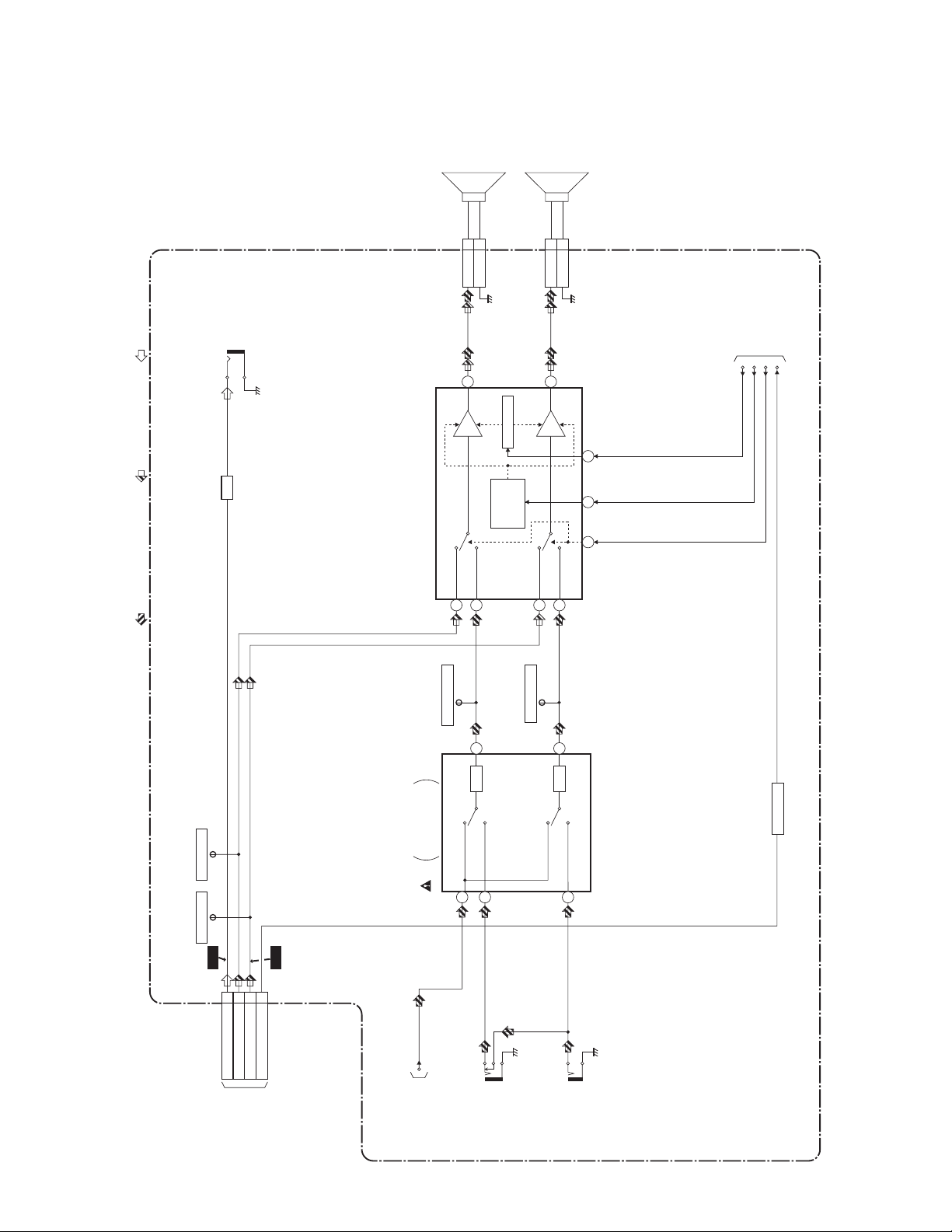
BLOCK DIAGRAMS < TV Section >
Audio Block Diagram
SP1801
SPEAKER
R-CH
SP1802
SPEAKER
L-CH
AUDIO (TV/LINE) SIGNAL DVD AUDIO SIGNAL DATA(AUDIO) SIGNAL
DIGITAL
JK1730
AMP
Q1731
AUDIO OUT
(COAXIAL)
CN1801
DVD
IC1801 (AUDIO AMP)
1
CL1801
SP-R 1
SP-GND 2
14
AMP
(R-CH)
LINE/TUNER
3
VOLUM E
MUTE
/STANDBY
CONTROL
(L-CH)
DVD
CL1802
SP-L 1
CN1802
11
AMP
LINE/TUNER
6
SP-GND 2
TO SYSTEM CONTROL
BLOCK DIAGRAM
DVD -L
VOLUME
SP-MUTE
7
212
8
DVD-AUDIO-MUTE
TP1402
AUDIO-R-OUT
TP1401
AUDIO-L-OUT
41
ATT
34
ATT
MAIN CBA
Q1732
SWITCHING
TP1404
DVD-R-OUT
TP1403
DVD-L-OUT
WF20
CN4
SPDIF 8
TO DVD AUDIO
11
DVD-AUDIO(R)
BLOCK DIAGRAM
WF19
DVD-AUDIO(L) 10
DVD-AUDIO-MUTE 9
<DVD SECTION>
CN4A
TV MICON/VIDEO
/CHROMA
/DEFLECTION
TUNER
IC1201
27
TU-AUDIO
TO IF/VIDEO
BLOCK DIAGRAM
LINE
19
JK1702
(R-CH)
AUDIO(R)
-IN
TUNER
LINE
21
JK1703
(L-CH)
AUDIO(L)
-IN
1-1
T9110BLA
Page 3

SCHEMATIC DIAGRAMS / CBA’S AND TEST POINTS
Standard Notes
WARNING
Many electrical and mechanical parts in this chassis
have special characteristics. These characteristics
often pass unnoticed and the protection afforded by
them cannot necessarily be obtained by using
replacement components rated for higher voltage,
wattage, etc. Replacement parts that have these
special safety characteristics are identified in this
manual and its supplements; electrical components
having such features are identified by the mark “#” in
the schematic diagram and the parts list. Before
replacing any of these components, read the parts list
in this manual carefully. The use of substitute
replacement parts that do not have the same safety
characteristics as specified in the parts list may create
shock, fire, or other hazards.
Notes:
1. Do not use the part number shown on these
drawings for ordering. The correct part number is
shown in the parts list, and may be slightly
different or amended since these drawings were
prepared.
2. All resistance values are indicated in ohms
(K = 10
3. Resistor wattages are 1/4W or 1/6W unless
otherwise specified.
4. All capacitance values are indicated in µF
(P = 10
5. All voltages are DC voltages unless otherwise
specified.
3
, M = 106).
-6
µF).
2-1 X6SN_SC
Page 4

LIST OF CAUTION, NOTES, AND SYMBOLS USED IN THE SCHEMATIC DIAGRAMS ON
THE FOLLOWING PAGES:
1. CAUTION: FOR CONTINUED PROTECTION AGAINST RISK OF FIRE, REPLACE ONLY
WITH SAME TYPE4A, 125V FUSE.
ATTENTION: UTILISER UN FUSIBLE DE RECHANGE DE MÊME TYPE DE4A, 125V.
2. CAUTION:
Fixed Voltage (or Auto voltage selectable) power supply circuit is used in this unit.
If Main Fuse (F1601) is blown, first check to see that all components in the power supply circuit are not defective before you connect the AC plug to the AC power supply. Otherwise it may cause some components in the
power supply circuit to fail.
3. Note:
1. Do not use the part number shown on the drawings for ordering. The correct part number is shown in the
parts list, and may be slightly different or amended since the drawings were prepared.
2. To maintain original function and reliability of repaired units, use only original replacement parts which are
listed with their part numbers in the parts list section of the service manual.
4. Voltage indications for PLAY and STOP modes on the schematics are as shown
below:
< DVD Section >
Unit: Volts
The same voltage for
both PLAY & STOP modes
231
5.0
5.0
(2.5)
Indicates that the voltage
is not consistent here.
5. How to read converged lines
1-D3
Distinction Area
Line Number
(1 to 3 digits)
Examples:
1. "1-D3" means that line number "1" goes to the line number
"1" of the area "D3".
2. "1-B1" means that line number "1" goes to the line number
"1" of the area "B1".
6. Test Point Information
: Indicates a test point with a jumper wire across a hole in the PCB.
: Used to indicate a test point with a component lead on foil side.
PLAY mode
STOP mode
< TV Section > Unit: Volts
Unit: Volts
5.0
The same voltage for
both TV & DVD modes
231
5.0
(2.5)
< 0 >
Indicates that the voltage
is not consistent here.
TV mode (Power on)
TV mode (Power off)
DVD mode
3
AREA D3
2
1
AREA B1
1-D3
ABCD
1-B1
: Used to indicate a test point with no test pin.
: Used to indicate a test point with a test pin.
2-2 X6SN_SC
Page 5

Main 3/7 Schematic Diagram < TV Section >
MAIN 3/7
Ref No. Pos it ion
IC1801
O-3
Q1731 Q-3
Q1732
O-1
CN1801
M-3
CN1802
M-4
TP1401
Q-2
TP1402
Q-2
TP1403
P-2
TP1404
P-2
TP1405
P-2
TP1732 Q-3
TP1733 O-1
TP1734 O-1
TRANSISTORS
CONNE CTORS
TEST POINTS
IC
2-3
T9110SCM3
Page 6

Different parts from the original model (6520FDF)
Ref. No. Description Part No.
MECHANICAL PARTS
A1X FRONT CABINET ASSEMBLY T9110UL 1EM120387
A1-1 FRONT CABINET T9101UB 1EM020160
A1-2 CONTROL PLATE T9110UL 1EM220322
A1-3 BRAND PLATE T9110UL-SV2000- 1EM421269
A3# RATING LABEL T9110UL ---------A4 Not used
A5 TRAY PANEL T9004UE 0EM302048
TB19# 20PF CHASSIS NO. LABEL TJ T9110UL ---------S1 CARTON T9110UL 1EM421272
S4 SERIAL NO. LABEL T9110UL ---------S5 LABEL EAS(H3761UD) MAKER NO.ZLLFNSLE1 ---------X2# OWNERS MANUAL T9110UL 1EMN20509
ELECTRICAL PARTS
MMA CBA 1ESA11071
MAIN CBA ---------C1607# CERAMIC CAP. 0.0047µF F CS CCG2HMN0F472
JC1861 CHIP RES.(1608) 1/10W 0 Ω RRXAZR5Z0000
JK1801 Not used
R1821 Not used
R1822 Not used
3-1 T9110PL
Page 7

WV20D5
T9110UL
2005-06-20
 Loading...