

Page 1
SUPPLEMENT
SERVICE MANUAL
This service manual shows only the differences between
the model WF24T5 and the original model 6424TF.
All other information is described in the service manual
of the model 6424TF.
23″ COLOR
TELEVISION
WF24T5
TABLE OF CONTENTS
Block Diagrams . . . . . . . . . . . . . . . . . . . . . . . . . . . . . . . . . . . . . . . . . . . . . . . . . . . . . . . . . . . . . . . . . .1-1
Schematic Diagrams / CBA’s and Test Points . . . . . . . . . . . . . . . . . . . . . . . . . . . . . . . . . . . . . . . . . . .2-1
Different parts from the original model (6424TF) . . . . . . . . . . . . . . . . . . . . . . . . . . . . . . . . . . . . . . . . .3-1
Page 2
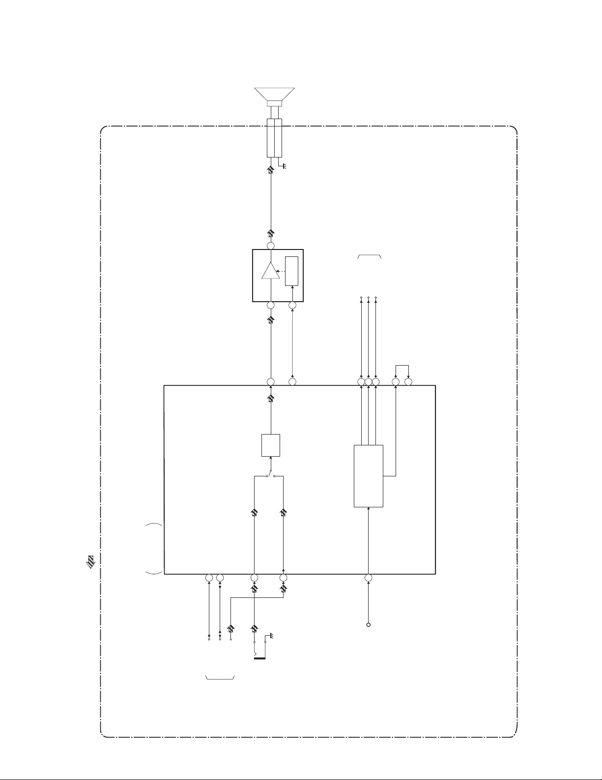
BLOCK DIAGRAMS
R
Audio/Power Control Block Diagram
1
SPEAKER
CN801 CLN801
SP-GND 2
SP801
SPEAKE
(AUDIO AMP)
IC801A
LINE
6
AMP
1
34
ATT
TUNER
MUTE
/STANDBY
2
57
A-MUTE
TO POWER
SUPPLY BLOCK
+5V-CTRL228+5V-CTRL
+8V-CTRL
40
18
POWER MANAGE.
/MCU RESET
13
12
RESET
MAIN CBA
AUDIO SIGNAL
TV MICON/VIDEO
/AUDIO/CHROMA
/DEFLECTION
IC111
SDA
58
56
SCL SCL
SDA
TU-AUDIO
TO IF/VIDEO/SYSTEM
CONTROL BLOCK
25
JK702
(FRONT)
AUDIO-IN
27
1-1
31
AL+9V
L3410BLA
Page 3
SCHEMATIC DIAGRAMS / CBA'S AND TEST POINTS
Standard Notes
Many electrical and mechanical parts in this chassis have special characteristics. These characteristics often
pass unnoticed and the protection afforded by them cannot necessarily be obtained by using replacement
components rated for higher voltage, wattage, etc. Replacement parts that have these special safety
characteristics are identified in this manual and its supplements; electrical components having such features are
identified by the mark “#” in the schematic diagram and the parts list. Before replacing any of these components,
read the parts list in this manual carefully. The use of substitute replacement parts that do not have the same
safety characteristics as specified in the parts list may create shock, fire, or other hazards.
Notes:
1. Do not use the part number shown on these drawings for ordering. The correct part number is shown in the
parts list, and may be slightly different or amended since these drawings were prepared.
2. All resistance values are indicated in ohms (K = 10
3. Resistor wattages are 1/4W or 1/6W unless otherwise specified.
4. All capacitance values are indicated in µF (P = 10
5. All voltages are DC voltages unless otherwise specified.
Note of Capacitors:
ML --- Mylar Cap. PP --- Metallized Film Cap. SC --- Semiconductor Cap. L --- Low Leakage type
Temperature Characteristics of Capacitors are noted with the following:
B --- ±10% CH --- 0±60 ppm/°C CSL --- +350~-1000 ppm/°C
3
, M = 106).
-6
µF).
Tolerance of Capacitors are noted with the following:
Z --- +80~-20%
Note of Resistors:
CEM --- Cement Res. MTL --- Metal Res. F --- Fuse Res.
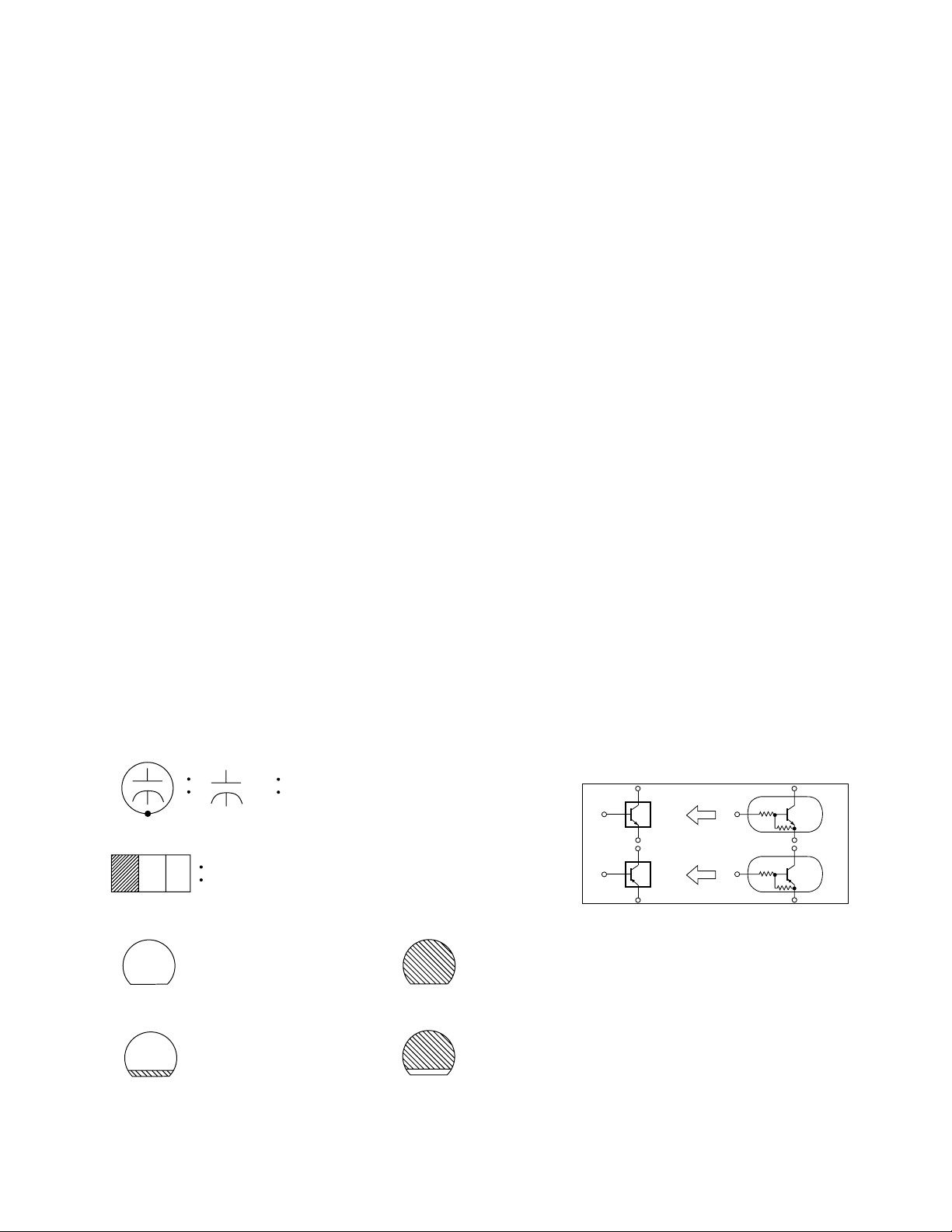
Capacitors and transistors are represented by the following symbols.
CBA Symbols
(Top View) (Bottom View)
+
Electrolytic Capacitor
(Bottom View)
Transistor or Digital Transistor
E C B
(Top View)
NPN Transistor
E C B
(Top View)
(Top View)
PNP Transistor
E C B
(Top View)
Schematic Diagram Symbols
Digital Transistor
E C B
NPN Digital Transistor
PNP Digital Transistor
E C B
2-1 L15N_SC
Page 4

LIST OF CAUTION, NOTES, AND SYMBOLS USED IN THE SCHEMATIC DIAGRAMS ON
THE FOLLOWING PAGES:
1. CAUTION:
CAUTION: FOR CONTINUED PROTECTION AGAINST RISK OF FIRE, REPLACE ONLY WITH SAME
TYPE_A,_V FUSE.
ATTENTION: UTILISER UN FUSIBLE DE RECHANGE DE MÊME TYPE DE_A,_V.
2. CAUTION:
Fixed Voltage (or Auto voltage selectable) power supply circuit is used in this unit.
If Main Fuse (F601) is blown, first check to see that all components in the power supply circuit are not
defective before you connect the AC plug to the AC power supply. Otherwise it may cause some components
in the power supply circuit to fail.
3. Note:
1. Do not use the part number shown on the drawings for ordering. The correct part number is shown in the
parts list, and may be slightly different or amended since the drawings were prepared.
2. To maintain original function and reliability of repaired units, use only original replacement parts which are
listed with their part numbers in the parts list section of the service manual.
4. Voltage indications on the schematics are as shown below:
Plug the TV power cord into a standard AC outlet.:
2
(Unit: Volt)
1
5.0
(3.0)
3
5.0
(3.0)
Power on mode
Power off mode
5. How to read converged lines
1-D3
Distinction Area
Line Number
(1 to 3 digits)
Examples:
1. "1-D3" means that line number "1" goes to the line number
"1" of the area "D3".
2. "1-B1" means that line number "1" goes to the line number
"1" of the area "B1".
6. Test Point Information
: Indicates a test point with a jumper wire across a hole in the PCB.
: Used to indicate a test point with a component lead on foil side.
: Used to indicate a test point with no test pin.
: Used to indicate a test point with a test pin.
Voltage
Indicates that the voltage
is not consistent here.
3
2
1
AREA D3
1-B1
AREA B1
1-D3
ABCD
2-2 L15N_SC
Page 5

Main 1/3 Schematic Diagram
MAIN 1/3
Ref No. Pos it ion
IC111
C-2
IC151
A-3
IC801A
C-1
Q111 D-1
Q321 E-1
Q361 B-4
CN801 A-2
ICS
TRANSISTORS
CONNE CTO R
2-3
L3410SCM1
Page 6

Different parts from the original model (6424TF)
Ref. No. Description Part No.
MECHANICAL PARTS
A2 CONTROL PLATE L3410UL 1EM320500
A5# RATING LABEL L3410UL ---------PB4# CHASISS NO. LABEL L1524V2 ---------PB6 CLOTH(65) L7735TR 65X10X0.5T 0EM402149
S1 CARTON L3410UL 1EM421309
S2 STYROFOAM TOP ASSEMBLY L3400UA 1EM420671
S3 STYROFOAM BOTTOM ASSEMBLY L3400UA 1EM420672
S4 SET SHEET 1150X1900 1EM421024
S5 SERIAL NO. LABEL L3410UL ---------S7 LABEL EAS(H3761UD) MAKER NO.ZLLFNSLE1 ---------S8 Not Used
S9 Not Used
X2# OWNER S MANUAL ENGLISH/SPANISH 1EMN20531
ELECTRICAL PARTS
MMA CBA 1ESA11076
C642 Not Used
C643 CERAMIC CAP. 0.0047µF F CS CCG2HMN0F472
R801 Not Used
JK801 Not Used
JS801 PCB JUMPER D0.6-P5.0 JW5.0T
3-1 L3410PL
Page 7

WF24T5
L3410UL
2005-06-22
 Loading...