

Symphonic SD-ODS-GN User Manual
3
Co mponent C he cklist
Co mponent C he cklist
LEFT
RIGHT
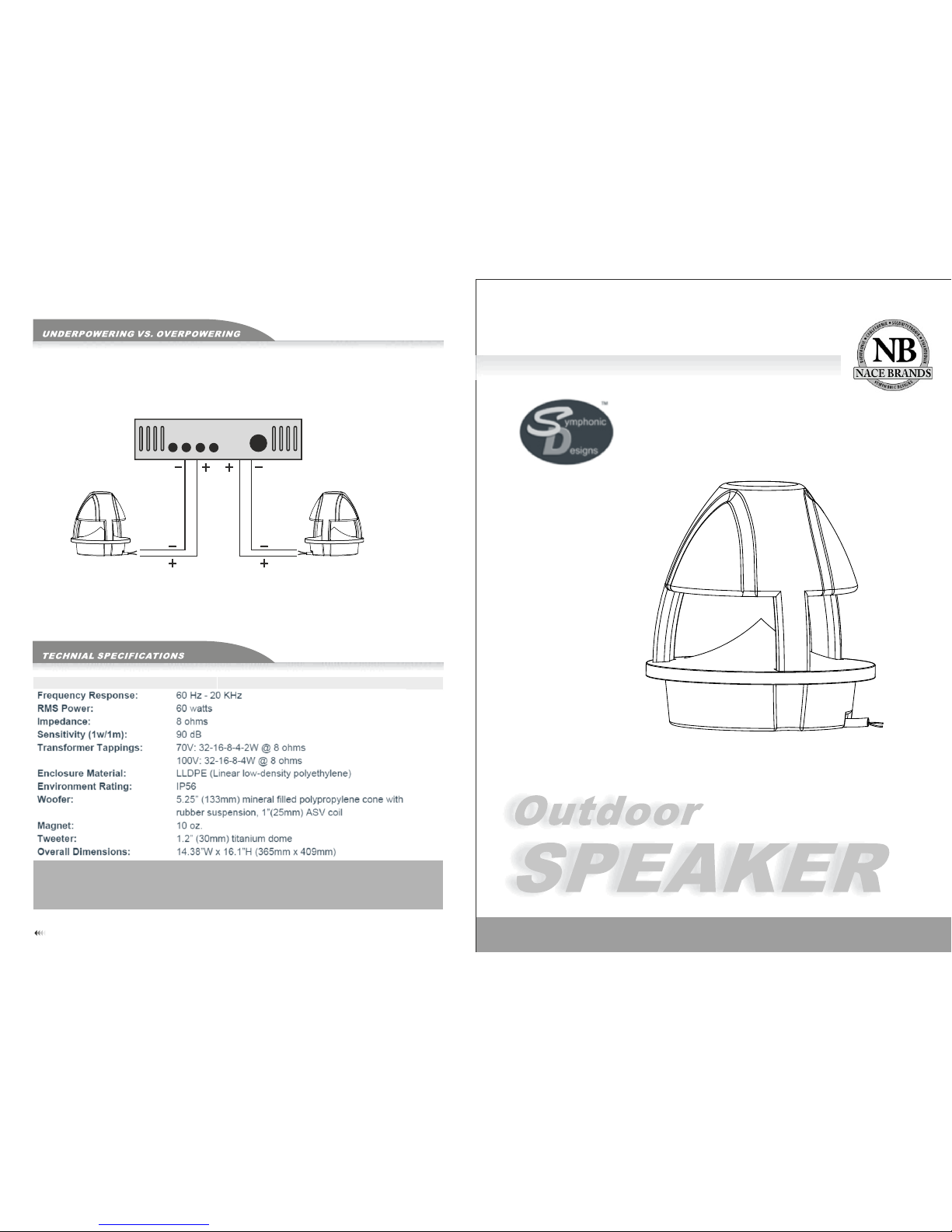
2-CHANNEL AMPLIFIER WITH 8ΩOUTPUT
2 SPEAKERS PER CHANNEL CONNECTED IN PARALLEL
8Ω
Obs er ve co rre ct
pol ar ity f or ma xim um
bas s pe rfo rma nce
INSTALLATION INSTRUCTI ON S
User Manual
SD-ODS-GN
8Ω
www.symphonicdesigns.net www.nacebrands.com
TM
21
•M ost spe aker da mage is c aused b y ampli fiers w ith too l ittle p ower (w attag e).
•An o verdr iven am plifi er clip s the wav eform s and sen ds dist ortio n to the sp eaker s.
•Cl ippin g is usua lly aud ible; i t may var y from a ha rsh sou nd to a fuz zy or unc lear so und.
•If y ou hear t his con ditio n at loud v olume l evels , turn do wn the vo lume un til the d istor tion is n o longe r prese nt.
•Da mage ca used by o perat ing the s peake rs at dis torte d volum e level s is not co vered b y the war ranty.
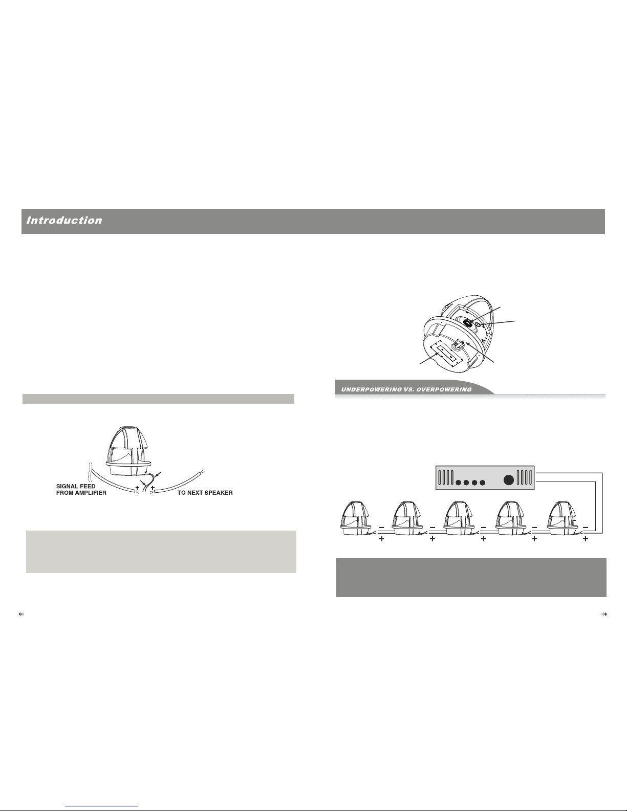
EXAMPLE OF 70V/100V SYSTEM CONFIGURATION
70V/100V
C
5 SPEAKERS CONNECTED IN PARALLEL USING 16W TAPS
NOTE :T he total num ber of speak ers multi plied by the ta p value cann ot exceed th e output pow er (in watts ) of the 70V
/100 V am plifier. The a bove examp le shows 5 tot al speaker s. Using the 1 6W taps, you wi ll need an amp lifier wi th at
leas t (5) x (16) = 80W. A good rule o f th umb is to selec t an amplifi er with 20% gr eater powe r; in this cas e, an amplif ier
that de livers ab out 100W.
Co mponent C he cklist
Read th ese inst ructio ns carefu lly before us ing the pro duct
1. When i nstall ing th e speaker s outdoo r, che ck that the w all structur e is reliable a nd that the s peaker is firm ly
attac hed.
2. Do not p lace the s peakers o n a turntable o r movabl e struct ure.
3. Do not t ouch or bu mp the woo fer and twe eter. If these are damaged , the sound will b e distorted.
4. Be sure when switching input devices that the amplifier is first turned off to prevent any damage.
5. Don’ t attemp t to clean t he speake rs with chemic al solvents as t his may damage t he paint surfa ce. Clean with
a dry clo th.
Red wire
Black wire
Connection
Locate the positive (+) and negative (-) wire on the rear of the speaker. Connect the positive (+) side of the
amplifier to the speaker (+) connector followed by connecting the negative side (-) to the speaker tab. Before
connecting each speaker, make sure that the polarities have not been inverted.
Anti-theft bracket
installation panel
Loudspeaker
Switch
Input
Symphonic Designs made every effort to provide accurate and detailed instruction for this product’s assembly and installation. Symphonic
Designs assumes no liability for any issues arising from these instructions. These brackets, all their parts and accessories must be used only
for the purpose they have been constructed. Symphonic Designs and it’s retailers are not directly or indirectly responsible for any damage to
persons and/or properties derived from the use of this product in an unsafe or different way for which it has been designed and constructed.
Several parts of this product are small pieces of hardware, therefore extreme care should be taken to keep them away from children.
Connections can be protected by using on of the following methods:
Soldering wires together using waterproof heat shrink tubing to waterseal.
Using waterproof wire connectors
Using connectors with immersion-resistant Crimp Slices (Raychem).
Using Grease Wire Caps
 Loading...