

Symmons Winslet Series, Winslet 5103, Winslet 5105, Winslet 5106 Operation & Maintenance Manual
Page 1

5103, 5105, 5106
Winslet® Series
Operation & Maintenance Manual
Model Numbers Specification
5103
Winslet Hand/Shower System
5105
Winslet Shower/Hand Shower System
5106
Winslet Tub/Shower/Hand Shower System
Modifications
CG
-1.5
1.5 gpm (5.7 L/min) flow restrictor
-2.0
2.0 gpm (7.6 L/min) flow restrictor
-H521-V
30" slide bar in place of wall cradle on hand
shower units (chrome and satin finishes only)
-IPS
1/2" female IPS connections
-REV
Reverse coring, hot on right, cold on left, for
back to back installations
5103
Hand shower system powered by the Temptrol® Pressure
Balancing valve. Features adjustable stop screw to limit
handle turn, 1 mode hand shower and standard 2.5 gpm
(9.5 L/min) ow restrictor.
5105
Shower/hand shower system powered by the Temptrol®
Pressure Balancing valve. Features adjustable stop screw
to limit handle turn, separate two function diverter,
1 mode hand shower, 1 mode showerhead and standard
2.5 gpm (9.5 L/min) ow restrictors.
5106
Tub/shower/hand shower system powered by the
Temptrol® Pressure Balancing valve. Features adjustable
stop screw to limit handle turn, separate three function
diverter, non-diverter tub spout, 1 mode hand shower,
1 mode showerhead and standard 2.5 gpm (9.5 L/min)
ow restrictors.
All components made from metal and nonmetallic
materials plated in standard polished chrome nish.
-X
Integral service stops
-X-CHKS
Integral check stops - for use in installations
where a positive shut-off device is used downstream of mixing valve
-STN
Satin Nickel finish
Note: Append appropriate -sufx to model number.
Compliance
-ASME A112.18.1/CSA B125.1
Warranty
Limited Lifetime - to the original end purchaser in
consumer/residential installations.
5 Years - for industrial/commercial installations.
Refer to symmons.com/warranty for complete warranty
information.
Page 2
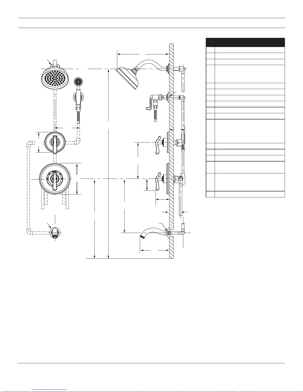
Dimensions
51065106
GG
AA
CC
H
H
E
E
Measurements
A Ø 2-1/2", 64 mm
B
B
D
D
F
F
I
I
M
M
B 12", 305 mm
C 6", 152 mm
Male 1/2" NPT thread must
D
E Ref. 77", 1956 mm
F 3-1/2", 89 mm
G Ø 5", 127 mm
H Ø 7-1/2", 191 mm
I 10", 254 mm
J Ø 2-1/2", 64 mm
K
L 12", 305 mm
M 2-7/8", 73 mm
N 3-1/8", 79 mm
O
P
Q 7", 178 mm
protrude 1/2" (13 mm)
from nished wall
5106
Ref. 32", 813 mm
5103, 5105
Ref. 42", 1067 mm
Rough-in
2-3/8" ± 1/2", 60 mm ± 13 mm
Male 1/2" NPT thread must
protrude 1/2" (13 mm)
from nished wall
N
Q
Q
P
P
N
L
L
K
JJ
FLOOR
FLOOR
Notes:
1) All dimensions measured from nominal rough-in (see O as reference).
2) Dimensions subject to change without notice.
K
O
O
2
Page 3

Parts Breakdown
C
B
Item Description Part Number
M
Replacement Parts
A Showerhead 4-166
A
N
B Shower Arm T-604
O
H
F
G
P
E
D
I
E
D
G
K
Q
J
J
HOT
Water Supply
COLD
Water Supply
C Shower Arm Flange T-605
D Handle Assembly T-611
E Dome Cover T-01197-PL
F
Diverter Escutcheon
G
H
I
J
K
L Tub Spout 512TS
M Hand Shower 462W
N Wall Cradle Flange T-606
O Wall Cradle T-613
P
Q
Screws
Mounting Plate
Shower Escutcheon
Screws
Mounting Plate
In-line Vacuum
Breaker & 60” Hose
T-607-NS-K001
T-609-NS-K001
EF-104
L
Notes:
1) Apply a bead of silicone around the perimeter of all shower trim
installed ush to the nished wall (less mounting plates and
brackets). Leave opening on bottom of escutcheons for weep hole.
2) Apply plumber tape to all threaded connections.
Notes:
1) Append -STN to part number for Satin Nickel
nish
2) Append -1.5 or -2.0 to showerhead or hand
shower for low ow.
Tools Required for Installation
Adjustable
Wrench
Allen
Wrench (1/8")
Phillips Head
Screwdriver
Plumber Tape
Silicone
3
Page 4

Installation
2
2
2
K
I
Note:
For valve body installation, please
see valve body installation guides.
1) Install mounting plate (H) to diverter valve (5105 diverter valve =
2DIV-BODY, 5106 diverter valve =
3DIV-BODY) and mounting plate (K)
to shower valve (4000-BODY).
Secure each with two screws (G,J).
1
G
H
K
1
3) Attach shower escutcheon (I) to
mounting plate (K).
Note: Tabs should snap into place.
4) Install dome covers (E) to valves
by turning clockwise.
E
1
5) Install diverter handle (D) and
shower handle (D) to valves.
Secure handles by tightening set
screws.
D
1
D
1
J
2) Attach diverter escutcheon (F) to
mounting plate (H).
F
Note: Tabs should snap into place.
2
H
Note: Handles should be facing the
6 o'clock position.
6) Install tub spout (L) to pipe tting.
E
Turn clockwise to secure.
1
2
L
1
4
Page 5

Installation
2
2
1
2
2
7) Install wall cradle ange (N) to
pipe tting. Turn clockwise to
secure.
1
N
8) Attach wall cradle (O) to wall cradle ange (N) turning clockwise to
tighten.
1
N
9) Attach shower arm (B) and
ange (C) to vertical shower pipe
turning clockwise to tighten.
1
2
C
B
10) Install showerhead (A) to
shower arm (B) turning clockwise to tighten.
11)
Attach large end of hand shower
hose (Q) to hand shower (M).
Attach small end of hand shower
hose (Q) and gasket to in-line
vacuum breaker (P). Connect
in-line vacuum breaker (P) to
wall cradle (O). Turn clockwise to
tighten.
M
Q
O
4
O
Operation (Temperature Control)
1) Turn shower handle counterclockwise approximately 1/4 turn
to put valve in cold position.
B
1
A
2) Turn shower handle counterclockwise approximately 1/2 turn
to put valve in warm position.
P
Q
3) Turn shower handle counterclockwise approximately 3/4 turn
to put valve in hot position.
3
5
Page 6

Operation (Diverter Control: 5105)
1) Cartridge is factory set to divert
to function 1.
POSITION 1
Note: Additional handle positions for same output are illustrated.
2) Turn handle to position 2 to divert
to function 2.
POSITION 2
Operation (Diverter Control: 5106)
1) Cartridge is factory set to divert
to function 1.
POSITION 1
2) Turn handle to position 2 to divert
to function 2.
POSITION 2
3) Turn handle to position 3 to share
functions 1 and 2.
POSITION 3
3) Turn handle to position 3 to divert
to function 3.
POSITION 3
4) Turn handle to position 4 to share
functions 2 and 3.
POSITION 4
5) Turn handle to position 5 to share
functions 1 and 3.
POSITION 5
6) Turn handle to position 6 to share
functions 1 and 2.
POSITION 6
Troubleshooting Chart
Problem Cause Solution
Clean nished trim area with a soft
Finish is spotting.
WARNING: This product can expose you to chemicals including lead, which is known to the state of California to
cause cancer, birth defects, or other reproductive harm. For more information, go to www.P65Warnings.ca.gov.
Symmons Industries, Inc. ■ 31 Brooks Drive ■ Braintree, MA 02184 ■ Phone: (800) 796-6667 ■ Fax: (800) 961-9621
Copyright © 2018 Symmons Industries, Inc. ■ symmons.com ■ gethelp@symmons.com ■ ZV-3063 REV B ■ 080118
Elements in water supply may cause
water staining on nish.
cloth using mild soap and water or a
non-abrasive cleaner and then quickly
rinse with water.
 Loading...