

Page 1
Unity
SLC-6610-1.5, SLC-6612-1.5
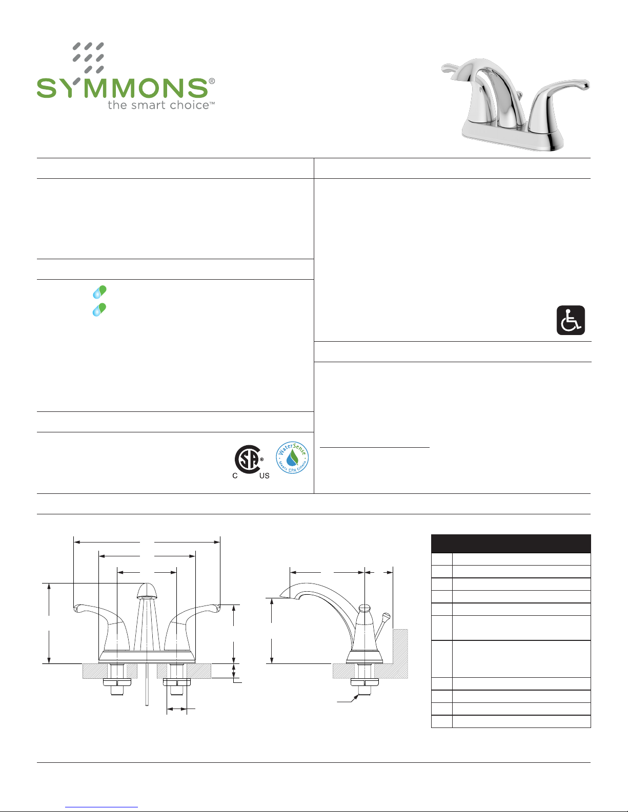
Two Handle Centerset Lavatory Faucet
Operation & Maintenance Manual
™
Model Numbers
SLC-6610-1.5
Unity Two Handle Centerset Lavatory Faucet
Less Rod
SLC-6612-1.5
Unity Two Handle Centerset Lavatory Faucet
Modifications
-0.5 0.5 gpm (1.9 L/min) aerator
-1.0 1.0 gpm (3.8 L/min) aerator
-G Grid drain
-Delete
Suffix
1.5
-STN Satin Nickel finish
Note: Append appropriate -sufx to model number.
2.2 gpm (8.3 L/min) aerator
Compliance
-NSF/ANSI 372, NSF/ANSI 61.9
-ASME A112.18.1/CSA B125.1
-WaterSense 1.5 gpm (5.7 L/min)
Certied by
CSA Group
Specification
Two handle centerset lavatory faucet featuring a
4” mounting conguration. Includes ceramic cartridges,
1/2” IPS inlet connections, 50/50 drain assembly and
standard 1.5 gpm (5.7 L/min) aerator. Components made
from brass and nonmetallic materials plated in standard
polished chrome nish.
Warranty
Limited Lifetime - to the original end purchaser in
consumer/residential installations.
5 Years - for industrial/commercial installations.
Refer to www.symmons.com/warranty for complete
warranty information.
For California Residents
WARNING: This product contains chemicals known to
the State of California to cause cancer, birth defects, or
other reproductive harm.
Dimensions
AA
BB
CC
DD
EE
HH
FF
GG
Note: Dimensions subject to change without notice.
II
KK
Measurements
A 9 3/4”, 248 mm
JJ
B 6 1/2”, 165 mm
C 4”, 102 mm
D 5 3/8”, 137 mm
E 3 7/8”, 98 mm
F
G
H 4 3/8”, 111 mm
I 4 7/8”, 124 mm
J Min. 2”, 51 mm
K 1/2-14 NPSM
Deck Thickness Ref.
Max. 1 1/2”, 38 mm
(3x) Hole Size
Min. Ø 1 1/4”, 32 mm
Max. Ø 1 1/2”, 38 mm
Page 2

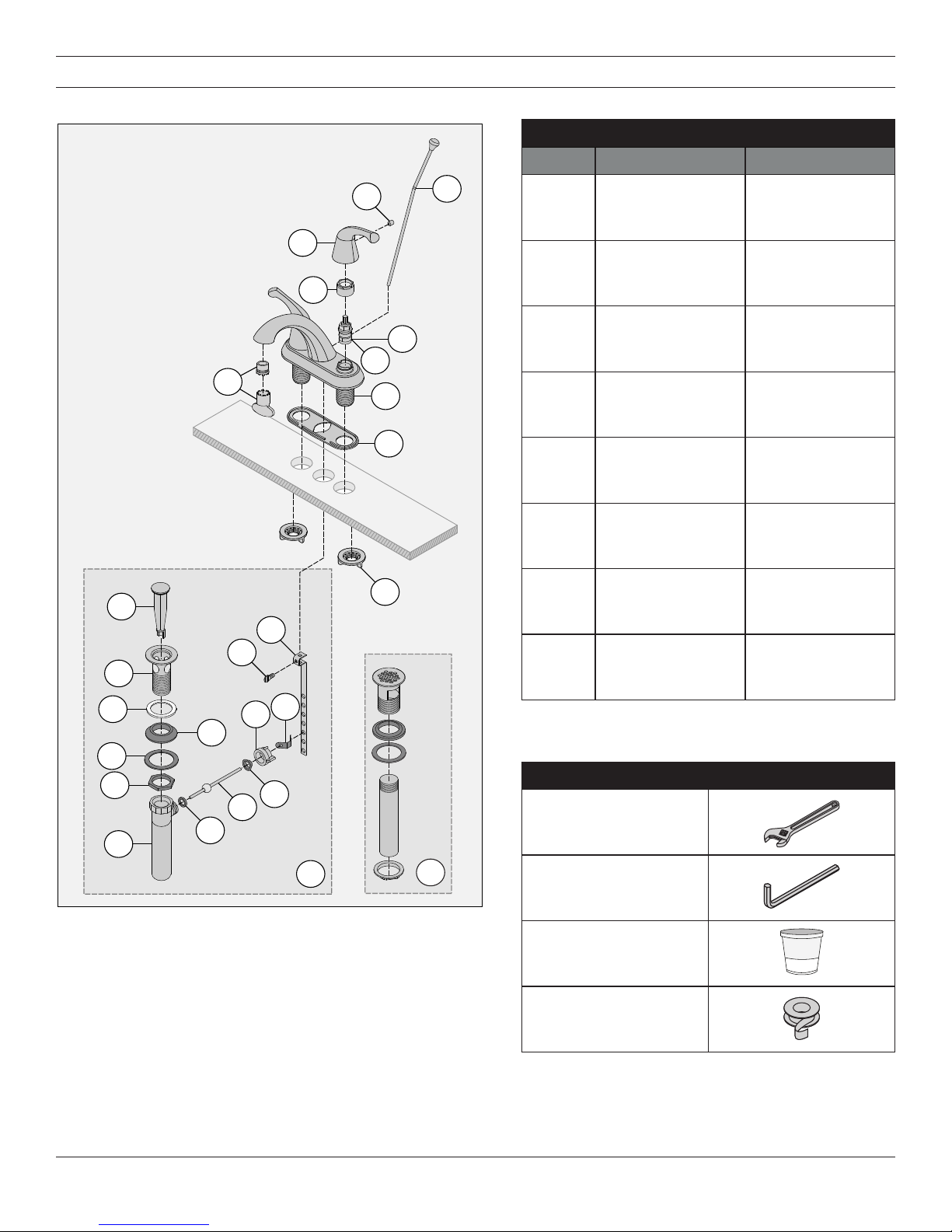
Parts Breakdown
Replacement Parts
Item Description Part Number
K1
K2
G
K14
K13
C
D
A
B
E
A
C
B Lift Rod RL-207*
E Hot Cartridge RL-075
(2x) Handle Kit RL-206*
F
H
I
J
F Cold Cartridge RL-076
LN-333-KIT (2.2)
G Aerator
I
J
K 50/50 Drain Assembly
L Grid Drain
Mounting Hardware RL-208
FLR-102-1.5-KIT (1.5)
LN-742-KIT (1.0)
FLR-102-0.5 (0.5)
RL-223*
(SLC-6612-1.5)
P-26*
(SLC-6610-1.5)
K3
K5
K6
K7
K4
K8
K9
K11
K12
K10
K
*Note: Append -STN to part number for Satin Nickel
nish.
Tools Required
Adjustable wrench
L
Allen wrench (3/32”)
PLUMBER
Plumber putty
Plumber tape
PUTTY
2
Page 3
2
3
4
4
K12
K9
K13
2
K14
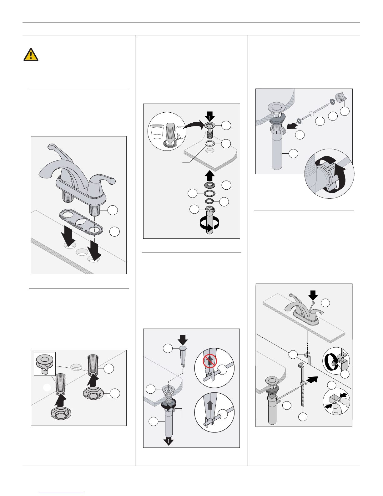
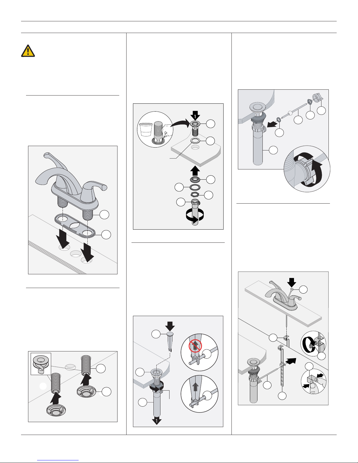
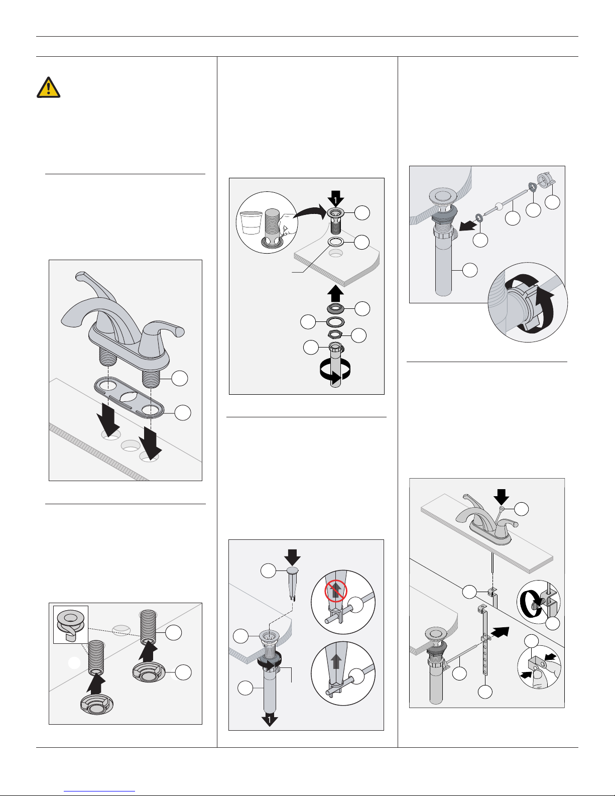
Installation
If replacing an older faucet
ensure water supply is turned
OFF before removing, then
turn faucet control valve ON to
relieve water pressure.
1) Insert faucet body (H) through
mounting gasket (I) and sink
holes.
H
I
2) Install mounting nuts (J) onto 1/2”
IPS inlet connections on faucet
body (H). Using a wrench, nish
with one-half turn. DO NOT overtighten.
3) Seat ange (K2) into sink (K3 gasket optional). Install gasket (K4),
washer (K5) and nut (K6) onto
ange (K2) from below sink, but
do not secure nut. Screw on tail
piece (K7) and hand tighten.
PLUMBER
PUTTY
K2
K3
OPTIONAL
2
K4
K5
K6
K7
3
4) Turn tail piece (K7) and ange
(K2) so pivot is facing toward
faucet. Pull assembly down into
drain hole. Secure hardware from
below sink. Install stopper (K1) in
the removable or non-removable
position.
3
K1
5) Attach inner washer (K8), pivot rod
(K9) and outer washer (K10) to tailpiece (K7). Hand tighten nut (K11)
to secure pivot rod (K9).
K11
K10
1
K8
K7
K9
6) Connect lift rod (B) to clevis strap
(K13) and secure with thumb
screw (K14). Insert pivot rod
(K9) through spring clip (K12)
and clevis strap (K13). Secure
with spring clip (K12) and adjust
linkage if necessary.
1
B
H
1
J
1
1
1
K2
K7
2
PIVOT
K13
3
Page 4
1
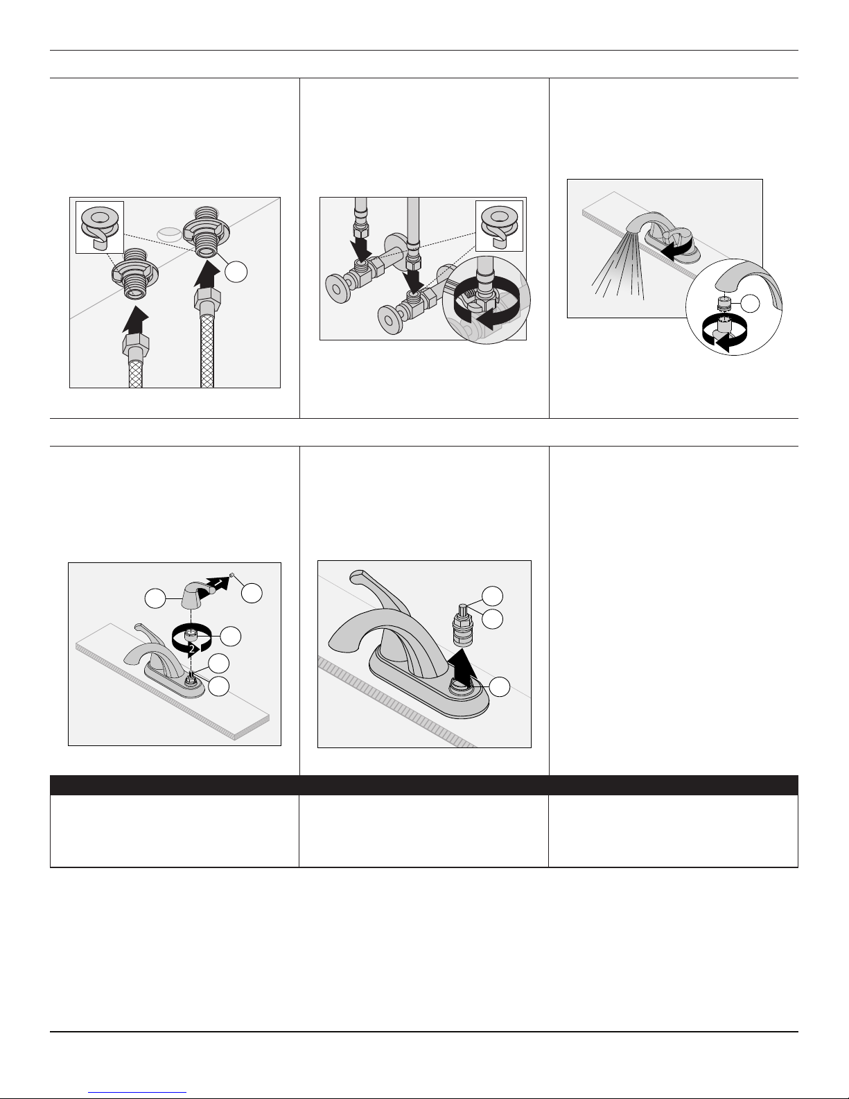
Installation
7) Attach supply lines to 1/2” IPS inlet
connections on faucet body (H).
Using a wrench, nish with one half
turn. DO NOT overtighten.
H
Maintenance
1) Remove set screw (A). Turning
counterclockwise, disassemble
handle (C) and nut (D) from cartridge (E or F).
8) Attach supply lines to shut-off
valves and hand tighten. Using a
wrench, nish with one-half turn.
DO NOT overtighten.
1
1
2
2) Remove cartridge (E or F) from
faucet body (H). Inspect for
debris.
necessary.
Replace cartridge if
9) Remove aerator (G) and ush
lines free of debris. Check for
leaks.
2
G
3) Install cartridge and handle assembly
following steps 1 and 2 in reverse.
C
E
F
Finish is spotting.
A
E
F
D
H
Troubleshooting Chart
Clean nished trim area with a soft
Elements in water supply may cause
water staining on nish.
cloth using mild soap and water or a
non-abrasive cleaner and then quickly
rinse with water.
Symmons Industries, Inc. ■ 31 Brooks Drive ■ Braintree, MA 02184 ■ Phone: (800) 796-6667 ■ Fax: (800) 961-9621
Copyright © 2015 Symmons Industries, Inc. ■ www.symmons.com ■ gethelp@symmons.com ■ ZV-3116 REV B ■ 112515
Page 5
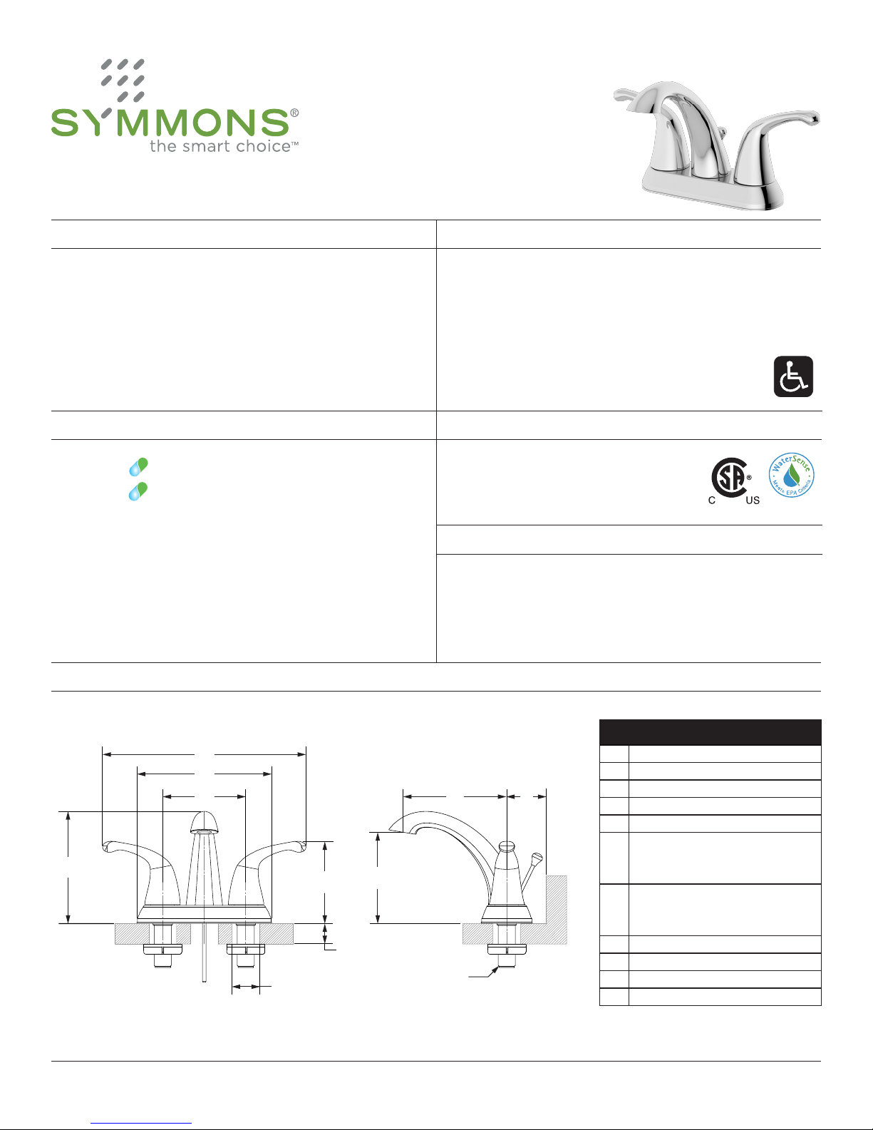
Unity
CSA Group
SLC-6610-1.5, SLC-6612-1.5
Dos manijas del grifo
Manual de Operación y Mantenimiento
™
Números de modelo
SLC-6610-1.5
Dos manijas del grifo Unity sin biela de elevación
SLC-6612-1.5
Dos manijas del grifo Unity
Modificaciones
-0.5 Aireador de 0.5 gpm (1.9 L/min)
-1.0 Aireador de 1.0 gpm (3.8 L/min)
-G Desagüe de rejilla
-Delete
Suffix
1.5
-STN Acabado en níquel satinado
Nota: Anexar el -complemento apropiado al número
Aireador de 2.2 gpm (8.3 L/min)
de modelo.
Especificación
Dos grifo de la manija que ofrecen una conguración de
4 “de montaje. Incluye cartuchos cerámicos, conexiones
1/2” IPS de entrada, 50/50 conjunto de drenaje y 1.5 gpm
(5,7 l / min) aireador estándar. Componentes hechos de
latón y materiales no metálicos chapados en acabado
cromo brillo estándar.
Cumplimiento
-NSF/ANSI 372, NSF/ANSI 61.9
-ASME A112.18.1/CSA B125.1
-WaterSense 1.5 gpm (5.7 L/min)
Garantía
Limitada de por vida - para el comprador original en
instalaciones para el consumidor/residenciales.
5 años - para instalaciones industriales/comerciales.
Consulte www.symmons.com/warranty para obtener
información completa sobre la garantía.
Certied by
Dimensiones
AA
BB
CC
DD
EE
HH
FF
GG
Nota: Las dimensiones pueden cambiar sin previo aviso.
II
KK
Medidas
A 9 3/4”, 248 mm
B 6 1/2”, 165 mm
JJ
C 4”, 102 mm
D 5 3/8”, 137 mm
E 3 7/8”, 98 mm
Referencia del grosor de la
F
Tamaño del oricio (3x)
G
Máx. Ø 1 1/2”, 38 mm
H 4 3/8”, 111 mm
I 4 7/8”, 124 mm
J Mín. 2”, 51 mm
K 1/2-14 NPSM
cubierta
Máx. 1 1/2”, 38 mm
Mín. Ø 1 1/4”, 32 mm
Page 6
Desglose de piezas
Repuestos
Artículo Descripción Número de pieza
K1
K2
G
K14
K13
C
D
A
B
E
A
C
B
E
Juego de manijas
(2x)
Varilla de
levantamiento
Cartucho para agua
caliente
RL-206*
RL-207*
RL-075
F
H
J
F
I
G Aireador
J
K
L Desagüe de rejilla
Cartucho para agua
I
Hardware de
Ensamble del
desagüe
fría
montaje
50/50
RL-076
LN-333-KIT (2.2)
FLR-102-1.5-KIT (1.5)
LN-742-KIT (1.0)
FLR-102-0.5 (0.5)
RL-208
RL-223*
(SLC-6612-1.5)
P-26*
(SLC-6610-1.5)
K3
K5
K6
K7
K4
K8
K9
K11
K12
K10
K
*Nota: Anexar -STN al número de pieza para el
acabado en níquel satinado.
Herramientas requeridas
Llave inglesa
L
Llave Allen (3/32”)
PLUMBER
Masilla de plomero
Cinta de plomero
PUTTY
6
Page 7
2
3
4
4
K12
K9
K13
2
K14
Instalación
Si está reemplazando otro
grifo, asegúrese de que el
suministro de agua esté CERRADO antes de quitarlo, luego
ABRA la válvula de control del
grifo para liberar la presión de
agua.
1) Inserte los conectores roscados
del cuerpo del grifo (H) a través
de la placa de masilla (I) y de la
placa de la plataforma.
H
I
2) Coloque las tuercas de los
conectores roscados (J) en
los conectores roscados (H) y
apriételas. Utilizando una llave,
termine con media vuelta. NO
apriete demasiado.
3) Ajuste la brida (K2) al lavabo (K3,
junta opcional). Instale la junta
(K4), la arandela (K5) y la tuerca
(K6) en la brida (K2) desde debajo
del lavabo, pero no ajuste la tuerca. Atornille la rejilla (K7) y ajuste
con la mano.
PLUMBER
PUTTY
K2
K3
OPTIONAL
2
K4
K5
K6
K7
3
4) Gire la rejilla (K7) y la brida (K2)
para que el pivote mire hacia el
grifo. Jale el ensamble hacia abajo
dentro del oricio de desagüe.
Asegure el hardware al ensamble
desde abajo del lavabo. Instale
el obturador (K1) en la posición
extraíble o no extraíble.
3
K1
5) Sujete la barra de pivote (K9) a la
rejilla (K7). Ajuste la tuerca (K11) a
mano en el sentido de las agujas
del reloj para asegurar la barra de
pivote (K9).
K11
K10
1
K8
K7
K9
6) Conecte la varilla de levantamiento
(B) a la barra con horquilla (K13) y
asegure con una tuerca de orejas
(K14). Inserte la barra de pivote (K9)
en la barra con horquilla (K13). Asegure con una grapa de resorte (K12)
y ajuste la conexión si es necesario.
1
B
H
1
1
1
1
J
K2
K7
2
K13
PIVOT
7
Page 8

1
Instalación
7) Conecte las líneas de suministro
a los conectores roscados del
grifo (H) y apriételas a mano.
Utilizando una llave, termine con
media vuelta. NO apriete demasiado.
H
Mantenimiento
1) Retire el tornillo de jación (A).
Volviendo hacia la izquierda, desmontar la manija (C) y la tuerca
(D) desde el cartucho (E/F).
8) Aplique cinta de plomero para
válvula de cierre. Utilizando una
llave, termine con media vuelta.
NO apriete demasiado.
1
1
2
2) Extraiga el cartucho (E/F) del cuerpo de válvula (H). Inspeccione
si hay desechos. Reemplace el
cartucho si es necesario.
9) Extraiga el aireador (G) y enjuague las líneas para que
queden libres de desechos. Verique que si hay pérdidas.
2
G
3) Reemplace el cartucho siguiendo
las instrucciones del paso 1 y 2 en
sentido inverso.
C
D
E
F
El acabado mancha.
A
E
F
H
Gráfi co de resolución de problemas
Los elementos del suministro de agua
pueden provocar que el agua manche
el acabado.
Limpie el área de reborde terminada
con un paño y jabón suaves y agua, o
un limpiador no abrasivo y luego en-
juague rápidamente con agua.
Symmons Industries, Inc. ■ 31 Brooks Drive ■ Braintree, MA 02184 ■ Phone: (800) 796-6667 ■ Fax: (800) 961-9621
Copyright © 2015 Symmons Industries, Inc. ■ www.symmons.com ■ gethelp@symmons.com ■ ZV-3116 REV B ■ 112515
Page 9

Unity
CSA Group
™
SLC-6610-1.5, SLC-6612-1.5
Robinet de salle de bain monopièce à deux poignées
Manuel d’Opération et de Maintenance
Numéro de modèle
SLC-6610-1.5
Robinet de salle de bain monopièce à deux
poignées aucune tige de levage Unity
SLC-6612-1.5
Robinet de salle de bain monopièce à deux
poignées Unity
Modifications
-0.5 Aérateur de 0,5 gpm (1,9 L/min)
-1.0 Aérateur de 1,0 gpm (3,8 L/min)
-G Drain de la grille
-Delete
Suffix
1.5
-STN Fini nickel satiné
Remarque: Juxtaposer le -sufxe approprié au numéro
Aérateur de 2,2 gpm (8,3 L/min)
demodèle.
Spécification
Le robinet de salle de bain monopièce à deux poignées
présente une conguration de xation de 4 po et
comprend des cartouches en céramique, des conduits
d’alimentation en eau IPS de 1/2 po, un ensemble pour
drain 50/50 et un aérateur standard de 1,5 gpm (5,7 L/
min). Composants faits de laiton et de matériaux
non métalliques au ni chrome poli standard.
Conforme
-NSF/ANSI 372, NSF/ANSI 61.9
-ASME A112.18.1/CSA B125.1
-WaterSense 1.5 gpm (5.7 L/min)
Certied by
Garantie
À vie limitée -à l’acheteur original dans les installations du
consommateur ou résidentielles.
5 ans - pour des installations commerciales et industrielles.
Se reporter au site www.symmons.com/warranty (en anglais) pour l’information complète concernant la garantie.
Dimensions
AA
BB
DD
CC
EE
HH
II
FF
GG
Remarque: Les dimensions sont sujettes à changer sans préavis.
KK
Mesures
A 9 3/4 po, 248 mm
B 6 1/2 po, 165 mm
JJ
C 4 po, 102 mm
D 5 3/8 po, 137 mm
E 3 7/8”, 98 mm
F
G
H 4 3/8 po, 111 mm
K 1/2-14 NPSM
Épaisseur du comptoir
Max. 1 1/2 po, 38 mm
(3x) Taille du trou
Min. Ø 1 1/4 po, 32 mm
Max. Ø 1 1/2 po, 38 mm
I 4 7/8 po, 124 mm
J Min. 2 po, 51 mm
Page 10

Pièces de remplacement
Pièces de remplacement
Article Description Numéro de pièce
K1
K2
G
K14
K13
C
D
A
B
E
A
C
B Tige de levage RL-207*
E
(2x) Ensemble de
poignée
Cartouche d’eau
chaude
RL-206*
RL-075
F
H
J
F
I
G Aérateur
I
J
K
L Drain de la grille
Cartouche d’eau
froide
Matériel de xation RL-208
Ensemble pour drain
50/50
RL-076
LN-333-KIT (2.2)
FLR-102-1.5-KIT (1.5)
LN-742-KIT (1.0)
FLR-102-0.5 (0.5)
RL-223*
(SLC-6612-1.5)
P-26*
(SLC-6610-1.5)
K3
K5
K6
K7
K4
K8
K9
K11
K12
K10
K
*Remarque: Juxtaposer le -STN au numéro de pièce
pour le ni nickel satiné.
Outils requis
Clef ajustable
L
Clef Allen (3/32 po)
PLUMBER
Mastic de plombier
Ruban de plombier
PUTTY
10
Page 11
2
3
4
4
K12
K9
K13
2
K14
Installation
Si vous remplacez un vieux
robinet, assurez-vous que
l’approvisionnement en eau
soit ÉTEINT (OFF) avant de
l’enlever, tournez ensuite la
vanne de contrôle du robinet
à ON pour alléger la pression
de l’eau.
1) Insérer les queues de xation du
corps de robinet (H) à travers la
plaque de mastic (I) et la plaque
de montage.
3) Bride à siège (K2) dans le vidoir
(K3 joint en option). Installez le
joint (K4), la rondelle (K5) et l’écrou
(K6) sur la bride (K2) en dessous
du vidoir, mais ne serrez pas
l’écrou. Vissez la pièce de raccordement (K7) et serrez à la main.
PLUMBER
PUTTY
K2
K3
OPTIONAL
2
K4
K5
K6
K7
5) Attachez la tige de pivotement (K9)
à la pièce de raccordement (K7).
Serrez l’écrou (K11) à la main dans
le sens des aiguilles d’une montre
pour xer la tige de pivotement
(K9).
K11
K10
1
K8
K7
K9
H
2) Installer les écrous de queue
de xation (J) sur les queues de
xation du robinet (H) et serrer. A
l’aide d’une clé, terminer avec un
demi-tour. NE PAS trop visser.
H
1
1
1
1
3
6) Connectez la tige de levage (B) à
la sangle de manille (K13) et xez
I
avec la vis à tête (K14). Insérez
la tige de pivotement (K9) dans
la sangle de manille (K13). Fixez
4) Tournez la pièce de raccordement
(K7) et la bride (K2) an que le pivot
avec la pince à ressort (K12) et
ajustez le couplage au besoin.
soit face au robinet. Tirez l’ensemble
dans le trou de drainage. Fixez le
matériel à l’ensemble en dessous du
vidoir. Installez le bouchon (K1) dans
la position amovible ou xe.
3
K1
K2
2
1
B
J
K7
PIVOT
K13
11
Page 12

1
Installation
7) Fixer les conduites d’alimentation
aux queues (H) de xation du
robinet et serrer à la main. A l’aide
d’une clé, terminer avec un demitour. NE PAS trop visser.
H
Coût d’entretien
8) Appliquer du ruban de plombier
pour la vanne d’entrée. A l’aide
d’une clé, terminer avec un demitour. NE PAS trop visser.
1
1
2
9) Enlevez l’aérateur (G) et rincez les
conduites de tout débris. Vérier
pour déceler les fuites.
2
G
1) Retirer la vis de réglage (A).
Tourner dans le sens inverse, de
démonter la poignée (C) et l’écrou
(D) de la cartouche (E/F).
C
A
D
E
F
Le ni est tâché.
2) Retirez la cartouche (E/F) du
corps de vanne (M). Inspectez
pour voir s’il y a des débris. Remplacez la cartouche au besoin.
E
F
H
Tableau de résolution des problèmes
Les éléments dans l’alimentation en
eau peuvent causer des tâches sur le
ni.
3) Remplacez la cartouche en suivant
les instructions à l’étape 1 et 2, mais
à l’envers.
Nettoyez la boiserie avec un chiffon
doux en utilisant un savon doux et de
l’eau ou un nettoyant non abrasif et
rincez rapidement avec de l’eau.
Symmons Industries, Inc. ■ 31 Brooks Drive ■ Braintree, MA 02184 ■ Phone: (800) 796-6667 ■ Fax: (800) 961-9621
Copyright © 2015 Symmons Industries, Inc. ■ www.symmons.com ■ gethelp@symmons.com ■ ZV-3116 REV B ■ 112515
 Loading...