

Symmons Temptrol 262BODY, Temptrol 261XBODY, Temptrol RTS-076, Temptrol 262XBODY Installation Instructions Manual
Temptrol® Pressure Balancing Valve
Installation Instructions
262BODY
(4 PORT)
262XBODY
(4 PORT, SERVICE STOPS)
261XBODY
(3 PORT, SERVICE STOPS)
RTS-076
(BRACKET)
COMPLIANCE
-ASME A112.18.1/CSA B125.1
-ASSE 1016
-Buy American Act Compliant
IMPORTANT / FOR INSTALLER
WARNING:
As the installer of this valve, you must first carefully read and understand the material covered in this manual before
installing and adjusting this valve per instructions. Failure to do so may compromise the installation, operation and/or
serviceability of this valve.
Do not install positive shut-o devices on the outlet of this valve, or devices that do not allow the valve to flow at
least 1.5 GPM at 45 psi inlet pressure. Exception: If a self-closing or slow-closing valve is installed on the outlet, the
supplies of the valve must be equipped with checks to eliminate hot to cold bypass in the event the valve’s handle is
not turned o after use.
When installing this valve, failure to adjust limit stop screw properly may result in serious scalding.
LIFETIME LIMITED WARRANTY
All warranty claims MUST be pre-approved by Symmons.
All parts and finishes of the Symmons products are
warranted to the original consumer purchaser to be free
from manufacturing defects in material and workmanship
for 5 years Non-Residential or Commercial Applications.
Symmons warrants to the original consumer purchaser/
end-user that any Symmons product will be free of
defects in material and workmanship during normal
domestic use for the life of your home.
Symmons recommends using a professional plumber
for all installation and repair. During the warranty
period, Symmons at its sole option, will provide
replacement part(s) or product (or, if no longer available,
a comparable product) to replace those which have
proven defective in materials or workmanship under
normal installation, use and service, FREE OF CHARGE
for the time period of 5 years from the date of purchase.
(BATTERIES NOT INCLUDED)
This warranty is extensive in that it covers replacement of
all defective parts and even finish, but these are the only
two things that are covered. Damage due to installation
error, product abuse, product misuse, or use of cleaners
containing abrasives, alcohols, or other organic solvents,
whether performed by a contractor, Service Company
or yourself are excluded from this warranty. Symmons
will not be responsible for labor charges and/or damage
incurred in installation or repair or replacement, nor for
any indirect, incidental or consequential damages, losses,
injury or costs of any nature relating to the bathing
products. Except provided by law, this warranty is in
lieu of and excluded all other warranties, conditions and
guarantees, whether expressed or otherwise, including
without restriction those of merchantability or of fitness
for use.
Some states do not allow the exclusion or limitation
of incidental or consequential damages, so the above
limitation of exclusion may not apply to you. This
warranty gives you specific legal rights, and you also may
have other rights which vary from state to state. This
warranty is not transferable. This warranty does not cover
damage or defects relating to misuse, abuse, negligence,
normal wear and tear, accident, acts of God, repairs or
alterations not authorized in writing by Symmons, or
improper installation, storage or handling.
The above mentioned warranty information includes each
product that falls under the following: Symmons Bathing
Products Warranty- Non-Residential or Commercial
Applications; Symmons Non-Electronic Lifetime
Faucet and Finish Limited Warranty Non-Residential or
Commercial Applications; Symmons Electronic Faucet
Limited Warranty - Non-Residential, Commercial and
Residential Applications; Symmons Bathing Products
Warranty- Residential Application Symmons NonElectronic Lifetime Faucet and Finish Limited Warranty
Residential Application
If you have any questions regarding technical support,
installation or concerns regarding our warranty plan,
please email us at GetHelp@symmons.com or call us at:
1-800-796-6667.
ZV-3247 REV B
1. RECOMMENDED TOOLS
FIGURE 1
Phillips Screwdriver Flathead Screwdriver
Adjustable Wrench
Safety Glasses Thread Seal Tape Measuring Tape
Torch
Solder
Pipe Cutter
Drywall Saw
(IPS Only)
Pipe Wrench
(CPVC Only)
CPVC Cement
(PEX Only)
PEX Crimping Tool
(PEX Only)
PEX Cold Expansion Tool
Level
Drill
(ProPress Only)
ProPress Tool
Copper, IPS, CPVC, PEX (Crimp) & PEX (Cold Expansion)
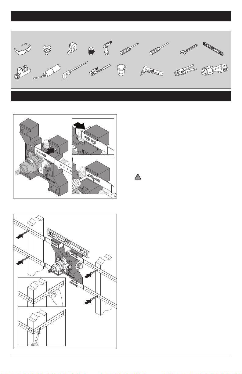
2. MOUNTING BRACKET INSTALLATION
2.1 Metal Straps
Mounting bracket is used to secure valve
between wall studs up to 24 inches, center to
center.
1. Place metal straps (x4) over screws. Screws
will come preassembled to bracket.
2. Pull metal straps tight against bracket ears.
Screws will protrude through small screw
hole in metal straps.
3. Drive screws into bracket to secure straps.
Use caution not to strip screws.
FIGURE 2.1
2.2 Install Bracket
FIGURE 2.3
FIGURE 2.4
ZV-3247 REV B
NOTE: Valve will come preassembled to
mounting bracket unless specified otherwise.
FIGURE 2.2
Mounting bracket will locate valve body in wall
cavity at appropriate depth (valve body rough-in
is not required).
1. Confirm valve body and mounting
2. Bend excess strap around wood studs.
3. Drive (4x) wood screws, at inward angle,
NOTE: If not using mounting bracket, see
STEP 5.1 for stringer mounts installation.
2
bracket are level. Drive (x4) wood screws
through metal straps into wood studs (see
FIGURE 2.2)
(see FIGURE 2.3)
through metal straps into sides of wood
studs (see FIGURE 2.4). Installing wood
screws at inward angle will pull metal straps
tight against wood studs.
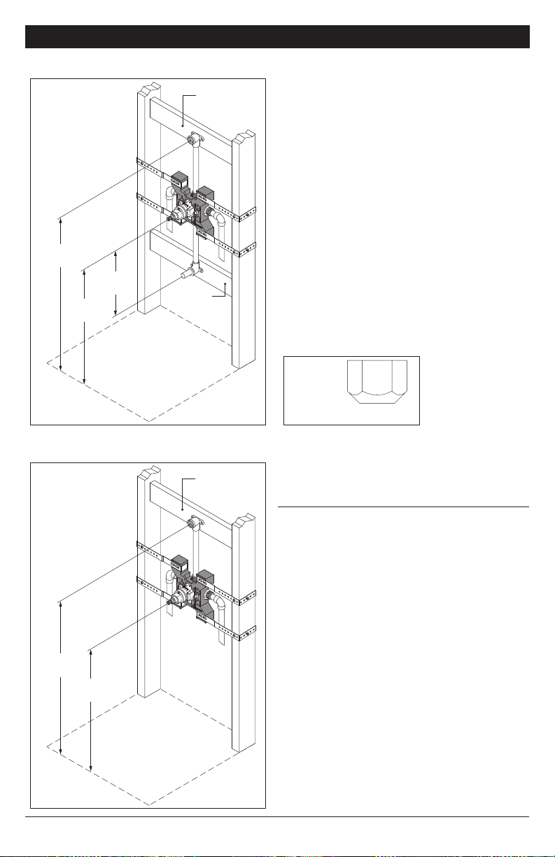
3.1 Tub/Shower Systems
FIGURE 3.1
77"
(1956mm)
12"
32"
(813mm)
(305mm)
INSTALL
BRACING
INSTALL
BRACING
3. DIMENSIONS AND MEASUREMENTS
Valve should be positioned 32 inches above the
tub basin floor. Shower arm should be 77 inches
above the tub basin floor. Tub spout should be
positioned approximately 12 inches below the
valve.
IMPORTANT: The design of this valve requires a
rigid copper tubing connection between the tub
port and the tub spout with no more than one (1)
90 degree bend allowed. Failure to do so, or to
substitute PEX, CPVC, or any other connection
type or outlet accessory such as a hand or
body-spray, other than the Symmons tub spout
provided, may result in excessive backpressure
through the system, and compromise operation.
When valve is used in shower only or tub spout
only installation, apply plumber tape to outlet
that will not be used and install the enclosed cap
to that outlet (see FIGURE 3.2).
FIGURE 3.2
FLOOR
3.2 Shower Systems
FIGURE 3.3
77"
(1956mm)
42"
(1067mm)
FLOOR
INSTALL
BRACING
CAP
1/2-14 NPT
Valve should be positioned 42 inches above the
tub basin floor. Shower arm should be 77 inches
above the tub basin floor.
NOTE: For ADA compliance (Americans with
Disabilities Act) consult your local municipality
for proper product choice and mounting
locations.
3
ZV-3247 REV B

4. DETERMINE WALL TYPE
4.1 T-176 Protective Shield 4.2 T-177 Valve Mounting Plate
FIGURE 4.1
-
F
I
N
T
I
N
S
A
H
T
E
R
D
O
P
M
I
E
C
A
F
R
U
S
S
I
H
T
W
A
L
L
M
U
S
T
B
E
F
L
U
F
S
O
H
M
W
O
I
T
T
H
T
O
B
FIGURE 4.2
Without service stops
With service stops
4.3 Drywall or Other Type Wall
FIGURE 4.3
1/2" (13 mm) or greater
protective shield
Wall Cutout Hole Size
3-1/2" (89 mm) min
4" (102 mm) max
finished wall
shower supply
Rough-in
± 1/2"
2-3/8"
(60 mm ± 13 mm)
pipe centerline
to front of
finished wall
hot & cold
supply inlets
tub spout
supply
Protective shield (T-176) is required for drywall,
plaster or other type walls with:
• 1/2 inch (13 mm) or greater wall thickness
1. Attach protective shield by snap fitting over
end of valve spindle to protect valve during
wall construction.
2. Finished wall must be flush with back side
of protective shield surface.
4.4 Thin Wall Installation
FIGURE 4.4
1/16" (2 mm) min
1/2" (13 mm) max
valve mounting plate
Wall Cutout Hole Size
3-1/2" (89 mm) min
4" (102 mm) max
finished wall
shower supply
Rough-in
± 1/2"
2-3/8"
(60 mm ± 13 mm)
pipe centerline
to front of
finished wall
hot & cold
supply inlets
tub spout
supply
Valve mounting plate (T-177) is required for
fiberglass or acrylic walls, and optional for
plaster or other type walls with:
• Minimum 1/16 inch (2 mm) wall thickness
• Maximum 1/2 inch (13 mm) wall thickness
1. Seat mounting plate against valve (see
FIGURE 4.2 for orientation).
2. Valve mounting plate must be flush with
inner wall.
4.5 Alternative Rough-ins
FIGURE 4.5
2" (51 mm)
Trim Series ± Tolerance
Oxford
Canterbury
Carrington
Temp Com
± 1/4" (± 6 mm)
± 1/2" (± 13 mm)
± 1/2" (± 13 mm)
± 1/2" (± 13 mm)
ZV-3247 REV B
Rough-in
± see table
pipe centerline
to finished wall
finished wall
When installing valve used with any of the
shower or tub/shower trims shown below,
reference rough-in dimensions as shown in
FIGURE 4.5 instead of standard valve rough-in:
Oxford
Canterbury
Temptrol
Carrington
Commercial
4
 Loading...