

Page 1
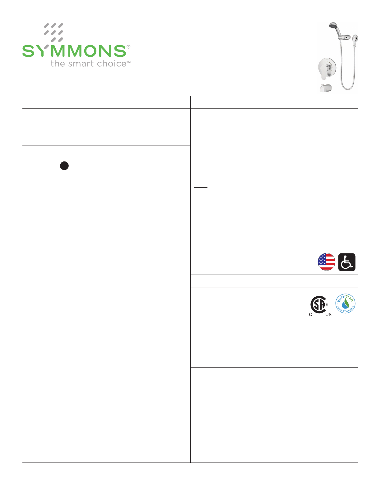
Identity
CG
6703, 6704
Operation & Maintenance Manual
™
Model Numbers
6703
Identity Hand Shower System
6704
Identity Tub/Hand Shower System
Modifications
-1.5 1.5 gpm (5.7 L/min) flow restrictor
-2.0 2.0 gpm (7.6 L/min) flow restrictor
-72
-B30
-B48
-CHKS Integral check stops - for use in
-IPS
-L/HS
-LP Loop handle
-LR Lever handle
-OP 13" oval plate
-QD
-R
-REB-TRM
-REV Reverse coring, hot on right, cold on
-SS Slip spout on any tub/hand shower unit
-STN Satin Nickel finish
-T724 24" slide / grab bar with ADA hand
-T736 36" slide / grab bar with ADA hand
-TRM Trim only, valve not included
-X Integral service stops - allows water
6' metal hose in place of 5' standard
metal hose
30" slide bar in place of wall cradle
48" slide bar in place of wall cradle
installations where a positive shut-off
device is used downstream of mixing valve
1/2" female IPS connections
Less hand shower
Quick disconnect on hand shower units
White vinyl hose in place of metal hose
Rebuild trim kit
left, for back to back installations
shower in place of standard hand shower unit
shower in place of standard hand shower unit
shutoff at valve for service
Specification
6703
Hand shower system powered by the Temptrol® pressurebalancing valve. Features adjustable stop screw to limit
handle turn, wall ell, in-line vacuum breaker, 60" exible
metal hose, hand shower cradle, 1 mode hand shower and
standard 2.5 gpm (9.5 L/min) ow restrictor. Components
made from metal and nonmetallic materials, plated in
standard polished chrome nish.
6704
Tub/hand shower system powered by the Temptrol®
pressure-balancing valve. Features adjustable stop screw
to limit handle turn, diverter tub spout, wall ell, in-line
vacuum breaker, 60" exible metal hose, hand shower
cradle, 1 mode hand shower and standard 2.5 gpm
(9.5 L/min) ow restrictor. Components made from metal
and nonmetallic materials, plated in standard polished
chrome nish.
Compliance
-ASME A112.18.1/CSA B125.1
-WaterSense 1.5 gpm (5.7 L/min)
2.0 gpm (7.6 L/min)
For California Residents
WARNING: This product contains chemicals known to the
State of California to cause cancer, birth defects, or other
reproductive harm.
Certied by
CSA Group
Warranty
Limited Lifetime - to the original end purchaser in
consumer/residential installations.
5 Years - for industrial/commercial installations.
Refer to www.symmons.com/warranty for complete
warranty information.
Note: Append appropriate -sufx to model number.
Page 2
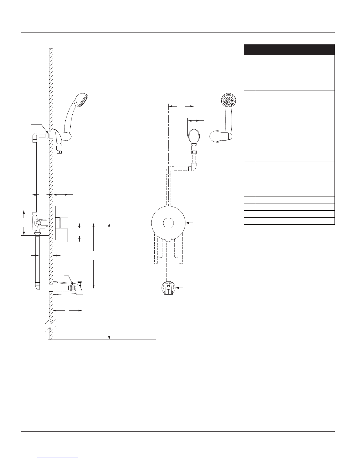
Dimensions
DD
AA
BB
CC
EE
KK
MM
Measurements
Male 1/2" NPT tting must
A
be recessed 1/4" (6 mm)
from nished wall
B 3-1/2", 89 mm
C 2-7/8", 73 mm
Shower Valve Hole Size
D
E 3-1/2", 89 mm
LL
F
G 12", 305 mm
H
I 5-1/4", 133 mm
J
K 6", 152 mm
L 2-1/8", 54 mm
M Ø 6-3/8", 162 mm
N Ø 2-5/8", 67 mm
Min. Ø 3", 76 mm
Max. Ø 4", 102 mm
Rough-in
2-3/8" ± 1/2", 60 mm ± 13 mm
Male 1/2" NPT tting must
protrude 4" (102 mm)
from nished wall
6703
Ref. 42", 1067 mm
6704
Ref. 32", 813 mm
FF
GG
HH
JJ
NN
II
FLOORFLOOR
Notes:
1) All dimensions measured from nominal rough-in (see F as reference).
2) Dimensions subject to change without notice.
2
Page 3
Parts Breakdown
A
E
N
H
L
M
B
C
D
G
F
Item Description Part Number
A Hand Shower EF-100*
B
D
C
E
F
GHVacuum Breaker
I
J
K
I
M
HOT
Water Supply
K Dome Cover T-19*
L
M
N
O
COLD
Water Supply
J
O Tub Spout 054*
*Note: Append -STN to part number for
Replacement Parts
Wall Ell
Set Screw
Mounting Plate
Wall Cradle
Screws
60" Hose
Handle
Set Screw
Escutcheon
Screws
Mounting Plate
EF-105*
EF-106*
EF-104*
RTS-084*
6700-ESC*
Satin Nickel nish.
Notes:
1) Apply a bead of silicone around the perimeter of all shower trim installed
ush to the nished wall (less mounting plates and brackets).
Leave opening on bottom of escutcheons for weep hole.
2) Apply plumber tape to all threaded connections.
Tools Required for Installation
Adjustable
Wrench
Allen Wrench
3/32"
Phillips Head
Screwdriver
Plumber Tape
Silicone
3
Page 4
2
2
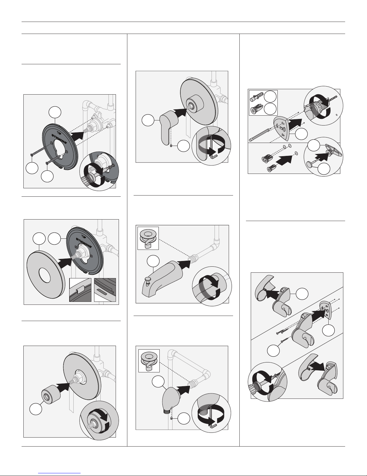
Installation
2
2
3
2
2
Note:
For valve body installation, please
see valve body manual.
1) Install shower mounting plate (N)
to shower valve. Secure with two
screws (M).
N
1
M
M
2) Attach shower escutcheon (L) to
shower mounting plate (N).
4) Install shower handle (I) to shower
valve. Secure shower handle with
set screw (J).
1
I
J
Note: Handle should be facing the 6
o’clock position.
5) Install tub spout (O) to pipe tting
Turn clockwise to tighten.
7) Place mounting plate
position, mark and drill 3/16" holes
for tile anchors (P1), 5/16" holes
for drywall anchors (P2). Install
anchors.
(C)
in
P1
P2
1
C
P2
3
4
P3
Note: For dry wall 1/2" thick or less,
insert anchor tool (P3) into drywall
anchor (P2) to secure behind wall
prior to installing wall cradle.
L N
Note: Tabs should snap into place.
3) Install dome cover (K) to shower
valve by turning clockwise.
1
O
6) Install wall ell
Tighten set screw (D) to secure.
1
(B)
to pipe tting.
B
1
1
8) Remove cover of hand shower
cradle
(E)
. Install cradle and
mounting plate
three screws
hand shower cradle.
1
(C)
. Secure with
(F)
. Replace cover on
E
2
C
F
4
K
D
4
Page 5
Installation
5
3
4
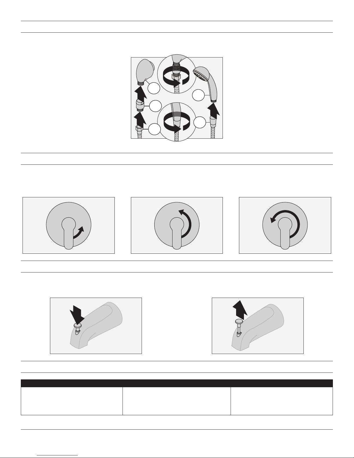
9) Attach vacuum breaker (G) to wall ell (B). Attach hose (H) to vacuum breaker. Attach hand shower (A) to hose (H). Turn
clockwise to tighten.
B
1
A
G
2
Operation (Temperature Control)
1) Turn shower handle counterclockwise approximately 1/4 turn
to put valve in cold position.
Operation (Diverter Control for 6704 only)
1) Diverter lever in down position for
tub spout operation.
2) Turn shower handle counterclockwise approximately 1/2 turn
to put valve in warm position.
H
H
3) Turn shower handle counterclockwise approximately 3/4 turn
to put valve in hot position.
2) Diverter lever in up position for
shower operation.
Troubleshooting Chart
Problem Cause Solution
Finish is spotting.
Symmons Industries, Inc. ■ 31 Brooks Drive ■ Braintree, MA 02184 ■ Phone: (800) 796-6667 ■ Fax: (800) 961-9621
Copyright © 2017 Symmons Industries, Inc. ■ symmons.com ■ gethelp@symmons.com ■ ZV-3197 REV B ■ 021617
Elements in water supply may cause
water staining on nish.
Clean nished trim area with a soft
cloth using mild soap and water or a
non-abrasive cleaner and then quickly
rinse with water.
Page 6

Identity
CG
6703, 6704
Manual de funcionamiento y mantenimiento
™
Números de modelo
6703
Sistema de ducha de mano Identity
6704
Sistema de bañera/ducha de mano Identity
Modificaciones
-1.5
-2.0
-72
-B30
-B48
-CHKS
-IPS
-L/HS
-LP
-LR
-OP
-QD
-R
-REB-TRM
-REV
-SS
-STN
-T724
-T736
-TRM
-X
Reductor de caudal de 1.5 gpm (5.7 L/min)
Reductor de caudal de 2.0 gpm (7.6 L/min)
Manguera de metal de 6 pies en vez de la
estándar de 5 pies
Barra deslizante de 30” en lugar del soporte
de pared
Barra deslizante de 48” en lugar del soporte
de pared
Válvulas de retención integradas - para usar en
instalaciones donde se usa un dispositivo de cierre
positivo aguas abajo de la válvula mezcladora
Salida de unión hembra de 1/2” I.P.S.
Sin ducha de mano
Manija en bucle
Manija de la palanca
Placa ovalada de 13"
Desconexión rápida en unidades de ducha
de mano
Manguera de vinilo blanco en lugar de la
manguera de metal
Juego del acabado de reconstrucción
Conexión inversa para instalaciones encontradas,
caliente a la derecha, frío a la izquierda.
Surtidor de deslizamiento en cualquier unidad
de bañera/ducha de mano
Acabado de níquel satinado
Barra agarradera/deslizante de 24” con
ducha de mano ADA en lugar de la unidad de
ducha de mano estándar
Barra agarradera/deslizante de 36” con
ducha de mano ADA en lugar de la unidad de
ducha de mano estándar
Borde solamente, válvula no incluida
Llaves de paso integradas - permiten el cierre
del agua en la válvula para el servicio
Especificación
6703
Sistema para ducha de mano con válvula compensadora
de presión Temptrol®. Incluye un tornillo con tope ajustable
para limitar el giro de la manija, codo de pared, igualador de
presión integrado, manguera metálica exible de 60", base de
ducha de mano, ducha de mano de 1 función y un restrictor
de caudal estándar de 2.5 gpm (9.5 L/min). Las piezas
están fabricadas con materiales metálicos y no metálicos
recubiertos con el acabado estándar de cromo pulido.
6704
Sistema para bañera y ducha de mano con válvula
compensadora de presión Temptrol®. Incluye un tornillo
con tope ajustable para limitar el giro de la manija,
desviador de surtidor de bañera, codo de pared, igualador
de presión integrado, manguera metálica exible de 60",
base de ducha de mano, ducha de mano de 1 función y
un restrictor de caudal estándar de 2.5 gpm (9.5 L/min).
Las piezas están fabricadas con materiales metálicos y no
metálicos recubiertos con el acabado estándar de cromo
pulido.
Cumplimiento
-ASME A112.18.1/CSA B125.1
-WaterSense 1.5 gpm (5.7 L/min)
2.0 gpm (7.6 L/min)
Certied by
CSA Group
Garantía
Limitada de por vida - para el comprador original
del producto en establecimientos del consumidor/
residenciales.
5 años - para instalaciones industriales y comerciales.
Consulte www.symmons.com/warranty para obtener
información más completa sobre la garantía.
Nota: Anexar el -complemento apropiado al número de modelo.
Page 7

Dimensiones
DD
AA
BB
FF
CC
EE
GG
KK
MM
Medidas
La rosca macho
NPT de 1/2” debe
A
B 3-1/2”, 89 mm
C 2-7/8", 73 mm
LL
D
E 3-1/2”, 89 mm
F
G 12", 305 mm
H
I 5-1/4", 133 mm
J
K 6", 152 mm
L 2-1/8", 54 mm
M Ø 6-3/8", 162 mm
N Ø 2-5/8", 67 mm
estar empotrada a
1/4” (6 mm)
de la pared terminada
Tamaño de los oricios
de la válvula para ducha
Mín. Ø 3”, 76 mm
Máx. Ø 4", 102 mm
Empotrado
2 3/8” ± 1/2”,
60 mm ± 13 mm
La rosca macho
NPT de 1/2” debe
sobresalir 4” (102 mm)
de la pared terminada
6703
Ref. 42", 1067 mm
6704
Ref. 32", 813 mm
HH
JJ
NN
II
PISOPISO
Notas:
1) Todas las dimensiones tomadas desde el empotrado (ver F para referencia).
2) Las dimensiones están sujetas a cambios sin previo aviso.
7
Page 8

Desglose de piezas
A
B
C
D
G
E
F
N
H
L
M
K
M
I
Suministro
de agua
CALIENTE
Suministro
O
de agua
FRÍA
J
Notas:
1) Aplique una gota de silicona alrededor del perímetro del borde de la
ducha a nivel de la pared terminada (salvo en las placas y soportes de
montaje). Deje un oricio en la parte inferior del escudete para drenar
la humedad.
2) Coloque cinta de teón en todas las salidas de unión roscadas.
Repuestos
Artículo Descripción
A
B
D
C
E
F
G
H
I
J
K
L
M
N
O
*Nota: Anexar -STN al número de pieza para
acabado de níquel satinado.
Ducha
de mano
Codo de pared
Tornillo de
presión
Placa de
montaje
Soporte de
pared
Tornillos
Igualador
de presión
Manguera
de 60”
Manija
Tornillo de
presión
Cubierta del
domo
Escudete
Tornillos
Placa de
montaje
Surtidor para
bañera
Número
de la pieza
EF-100*
EF-105*
EF-106*
EF-104*
RTS-084*
T-19*
6700-ESC*
054*
Herramientas necesarias
para la instalación
Llave inglesa
Llave Allen
3/32"
Destornillador
de cruz
Cinta de teón
Silicona
8
Page 9

2
2
Instalación
2
2
3
2
2
Nota:
Para instalar el cuerpo de la válvula,
vea el manual de la válvula.
1) Instale la placa de montaje (N) a la
válvula de la ducha. Sujétela con
dos tornillos (M).
N
1
M
M
2) Una el escudete de la ducha (L) a la
placa de montaje de la ducha (N).
4) Instale la manija de la ducha (I) en
la válvula de la ducha. Sujete la
manija de la ducha con el tornillo
de presión (J).
1
I
J
Nota: La manija debe situarse en la
posición de las 6 en punto.
5) Instale el surtidor para la bañera
(O) a la conexión de la tubería
girándolo en el sentido de las
manecillas del reloj para apretar.
7) Coloque la placa de montaje (C)
en su posición, marque y taladre
agujeros de 3/16" para las anclas
para mosaico (P1), agujeros de
5/16" para las anclas para yeso
(P2). Instale las anclas.
P1
P2
1
C
P2
3
4
P3
Nota:Para paredes de yeso de
1/2" de grosor o menos inserte la
herramienta para anclas (P3) en la
ancla para yeso (P2) para sujetarla
detrás de la pared antes de instalar
el soporte de pared.
L N
Nota: Las lengüetas deben
encajar en sus sitios.
3) Instale la cubierta del domo (K) a la
válvula de la ducha girándola en el
sentido de las manecillas del reloj.
1
O
6) Instale el codo de pared (B)
en el conector de la tubería.
Apriete el tornillo de presión
(D) para sujetarlo.
1
B
1
1
8) Retire la cubierta del soporte de
la ducha de mano (E). Instale el
soporte y la placa de montaje (C).
Sujete con tres tornillos (F). Vuelva
a colocar la cubierta del soporte
de la ducha de mano.
1
E
2
C
F
4
K
D
9
Page 10

Instalación
5
3
4
9) Una el igualador de presión (G) al codo de pared (B). Una la manguera (H) al igualador de presión. Una la ducha de
mano (A) a la manguera (H). Gire en el sentido de las manecillas del reloj para apretar.
B
1
A
G
2
H
Funcionamiento (Control de temperatura)
1) Gire el mango de la ducha 1/4 de
vuelta en sentido contrario a las
manecillas del reloj para colocar la
válvula en la posición de agua fría.
Funcionamiento (Control de desviador solo para 6704)
1) Palanca del desviador hacia
abajo para utilizar el surtidor
para bañera.
2) Gire el mango de la ducha 1/2
de vuelta en sentido contrario
a las manecillas del reloj para
colocar la válvula en la posición
de agua tibia.
H
3) Gire el mango de la ducha 3/4
de vuelta en sentido contrario
a las manecillas del reloj para
colocar la válvula en la posición
de agua caliente.
2) Palanca del desviador hacia arriba
para utilizar la ducha.
Tabla de resolución de problemas
Problema Causa Solución
El acabado se está manchando.
Symmons Industries, Inc. ■ 31 Brooks Drive ■ Braintree, MA 02184 ■ Teléfono: (800) 796-6667 ■ Fax: (800) 961-9621
Copyright © 2017 Symmons Industries, Inc. ■ symmons.com ■ gethelp@symmons.com ■ ZV-3197 REV B ■ 021617
Las partículas en el suministro
de agua pueden provocar que
el agua manche el acabado.
Limpie el área del acabado utilizando
un paño suave, jabón neutro y agua, o
con un limpiador no abrasivo y luego
enjuague rápidamente con agua.
Page 11

Identity
CG
6703, 6704
Manuel d'utilisation et d'entretien
™
Numéros de modèle
6703
Système de douche à main Identity
6704
Système de douche à main/baignoire Identity
Modifications
-1.5
-2.0
-72
-B30
-B48
-CHKS
-IPS
-L/HS
-LP
-LR
-OP
-QD
-R
-REB-TRM
-REV
-SS
-STN
-T724
-T736
-TRM
-X
Remarque: Juxtaposer le -sufxe approprié au numéro de modèle.
Réducteur de débit de 1,5gpm (5,7L/min)
Réducteur de débit de 2,0gpm (7,6L/min)
Boyau de 6 pieds au lieu du boyau en métal
standard de 5 pieds
Barre coulissante de 30 pouces au lieu du
support mural
Barre coulissante de 48 pouces au lieu du
support mural
Valve d'arrêt intégrée - pour une utilisation
dans les installations où un dispositif de
coupure intégrale est utilisé en aval de la
vanne de mélange.
Raccords IPS femelles de 1/2po
Moins la douche à main
Poignée en boucle
Poignée en levier
Plaque ovale de 13po
Débranchement rapide des accessoires de la
douche à main
Tuyau de vinyle blanc au lieu du tuyau de métal
Restaurez la trousse de finition
Corps central inversé, l'eau chaude à
la droite, l'eau froide à la gauche, pour
installations dos à dos
Bec de baignoire à enfiler sur toute unité de
baignoire/douche à main
Fini nickel satiné
Barre coulissante / d'appui de 24 pouces
avec douche à main ADA au lieu de l'unité de
douche à main standard
Barre coulissante / d'appui de 36 pouces
avec douche à main ADA au lieu de l'unité de
douche à main standard
Garniture seulement, vanne non incluse
Robinet d’interruption du service - permet la
coupure de l'eau à la vanne pour le service
Spécifications
6703
Système de douche à main alimenté par la vanne à
pression autorégularisée Temptrol®. Comprend une vis
d'arrêt réglable pour limiter la rotation de la poignée, un
coude mural, un brise-vide en ligne, un tuyau de métal
exible de 60po, un support mural de la douche à main,
une douche à main à mode unique et un réducteur de
débit standard de 2,5gpm (9,5L/min). Les composants
sont faits de matériaux métalliques et non métalliques au
ni chrome poli standard.
6704
Système de douche à main/baignoire alimenté par la
vanne à pression autorégularisée Temptrol®. Comprend
une vis d'arrêt réglable pour limiter le tournage de la
poignée, un bec de baignoire déviateur, un coude mural,
un brise-vide en ligne, un tuyau de métal exible de 60po,
un support mural de la douche à main, une douche à
main à mode unique et un réducteur de débit standard
de 2,5gpm (9,5L/min). Les composants sont faits de
matériaux métalliques et non métalliques au ni chrome
poli standard.
Conformité
-ASME A112.18.1/CSA B125.1
-WaterSense 1,5 gpm (5,7 L/min)
2,0 gpm (7,6 L/min)
Certied by
CSA Group
Garantie
À vie limitée–à l'acheteur original dans les installations
résidentielles/à l'usage du consommateur.
5 ans–pour des installations commerciales et
industrielles. Se reporter au site www.symmons.com/
warranty pour des informations complètes concernant
la garantie.
Page 12

Dimensions
DD
AA
BB
FF
CC
EE
GG
KK
MM
Mesures
Raccord NPT
1/2po mâle doit
A
B 3-1/2 po, 89mm
C 2-7/8 po, 73 mm
LL
D
E 3-1/2 po, 89mm
F
G 12 po, 305 mm
H
faire saillie de 4po (102 mm)
I 5-1/4 po, 133mm
J
K 6 po, 152 mm
L 2-1/8 po, 54mm
M Ø 6-3/8 po, 162 mm
N Ø 2-5/8 po, 67 mm
être encastré à
1/4po (6mm)
du mur ni
Taille du trou pour
la vanne de douche
Min. Ø3po, 76mm
Max. Ø 4po, 102mm
Robinetterie brute
2-3/8 po ± 1/2po,
60 mm ± 13 mm
Raccord NPT
1/2po mâle doit
du mur ni
6703
Réf.42po, 1067mm
6704
Réf.32po, 813mm
HH
JJ
NN
II
PLANCHERPLANCHER
Remarques:
1) Toutes les dimensions sont mesurées à partir de la robinetterie brute nominale (voir F en référence).
2) Les dimensions sont sujettes à modication sans préavis.
12
Page 13

Liste des pièces
A
B
Article Description
Pièces de rechange
Numéro
de pièce
C
A Douche à main EF-100*
D
G
E
F
N
D
C
E
F
B
H
L
M
G
H
I
J
K
M
I
Alimentation
en eau
CHAUDE
K Couvercle en dôme T-19*
L
M
N
O
Alimentation
en eau
FROIDE
O Bec de baignoire 054*
Coude mural
Vis de pression
Plaque de montage
Support mural
Vis
Brise-vide
Tuyau de 60po
Assemblage
Vis de pression
Rosace
Vis
Plaque de montage
EF-105*
EF-106*
EF-104*
RTS-084*
6700-ESC*
J
*Remarque: Juxtaposer le -STN au numéro
de pièce pour le ni nickel satiné.
Remarques:
1) Appliquez un joint de silicone autour du périmètre de la garniture de
la douche installée à égalité avec le mur ni (moins les plaques et les
supports de xation). Laissez une ouverture au fond de la rosace pour
l'évacuation.
2) Appliquez du ruban de plombier à toutes les connections letées.
Outils requis pour l'installation
Clef ajustable
Clef Allen
3/32 po
Tournevis à
tête cruciforme
Ruban de
plombier
Silicone
13
Page 14

2
2
Installation
2
2
3
2
2
Remarque: Pour l'installation du
corps de vanne, veuillez consulter le
manuel du corps de vanne.
1) Installez la plaque de montage
de la douche (N) à la vanne de
douche. Fixez avec deux vis (H).
N
1
M
M
2) Attachez la rosace de douche (L) à la
plaque de xation de la douche (N).
L N
4) Installez la poignée de douche
(I) à la vanne de douche. Fixez la
poignée de douche avec les vis de
pression (J).
1
I
J
Remarque: La poignée doit être
orientée vers la position 6h sur
une horloge.
5) Installez le bec de baignoire (O) au
raccord de tuyauterie en tournant
dans le sens horaire pour serrer.
7) Placez la plaque de montage
(C) en position, marquez et
percez des trous de 3/16po
pour l'ancrage pour céramique
(P1) et des trous de 5/16po pour
l'ancrage pour cloison sèche (P2).
Installez les dispositifs d'ancrage.
P1
P2
1
C
P2
3
4
P3
Remarque: Pour une cloison sèche
de 1/2po d'épaisseur ou moins,
insérer l'outil d'ancrage (P3) dans
le dispositif d'ancrage (P2) de la
cloison pour le xer derrière le mur
avant d'installer le support mural.
Remarque: Les languettes devraient
s'enclencher dans la bonne position.
3) Installez le couvercle en dôme (K)
à la vanne de douche en tournant
dans le sens des aiguilles d'une
montre.
1
K
O
6) Installez le coude mural (B) au
raccord de tuyauterie. Serrez les
vis de pression (D) pour xer en
place.
1
B
1
1
D
8) Enlevez le couvercle du support
de la douche à main (E). Installez
le support mural et la plaque de
montage (C). Fixez avec trois vis
(F). Remettre le couvercle sur le
support mural de la douche à
main.
1
E
2
C
F
4
14
Page 15

Installation
5
3
4
9) Fixez le brise-vide (G) au coude mural (B). Attachez le boyau (H) au brise-vide. Attachez la douche à main (A) au boyau
(H). Tournez dans le sens des aiguilles d'une montre pour serrer.
B
1
A
G
2
H
H
Fonctionnement (Contrôle de la température)
1) Tournez la poignée de douche dans
le sens contraire des aiguilles d'une
montre approximativement 1/4 de
tour pour mettre la vanne dans la
position d'eau froide.
Fonctionnement (Contrôle de dérivation 6704 seulement)
1) Le levier de dérivation dans
la position vers le bas pour le
fonctionnement du bec de baignoire.
2) Tournez la poignée de douche dans
le sens contraire des aiguilles d'une
montre approximativement 1/2 de
tour pour mettre la vanne dans la
position d'eau tiède.
3) Tournez la poignée de douche dans
le sens contraire des aiguilles d'une
montre approximativement 3/4 de
tour pour mettre la vanne dans la
position d'eau chaude.
2) Le levier de dérivation dans la
position vers le haut pour le
fonctionnement de la douche.
Tableau de résolution des problèmes
Symptôme Cause Solution
Le ni est tâché.
Symmons Industries, Inc. ■ 31 Brooks Drive ■ Braintree, MA 02184 ■ Téléphone: (800)796-6667 ■ Télécopieur: (800) 961-9621
Copyright © 2017 Symmons Industries, Inc. ■ www.symmons.com ■ gethelp@symmons.com ■ ZV-3197 REV B ■ 021617
Les éléments présents dans l'eau
peuvent causer des tâches sur le ni.
Nettoyer la zone avec un chiffon doux
en employant de l'eau et du détergent
doux ou un nettoyant non abrasif et
rincer rapidement à l'eau.
 Loading...