

Page 1
®
Dia
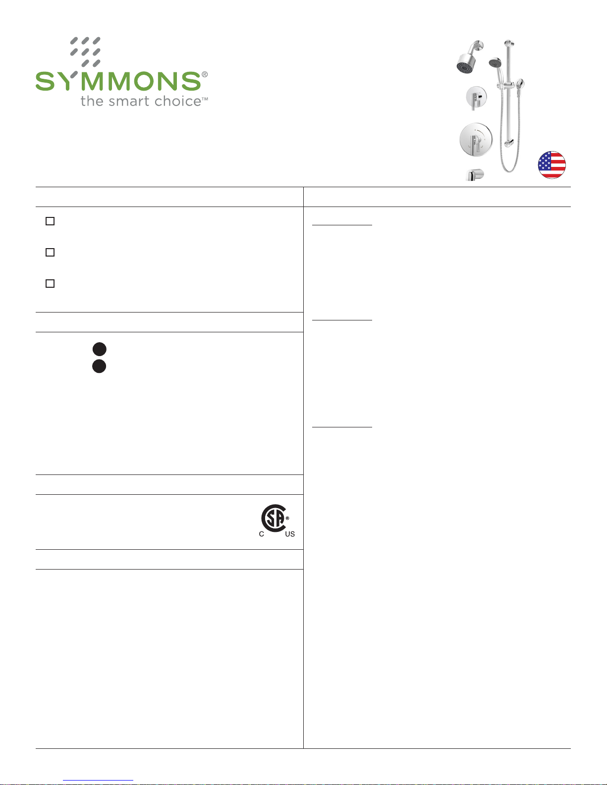
3503-H321-V, 3505-H321-V, 3506-H321-V
Shower System Series
Operation & Maintenance Manual
Model Numbers Specification
3503-H321-V
Hand Shower System
3505-H321-V
Shower/Hand Shower System
3506-H321-V
Tub/Shower/Hand Shower System
Options/Modifications
-1.5 1.5 gpm (5.7 L/min) flow restrictor
-2.0 2.0 gpm (7.6 L/min) flow restrictor
Delete
Suffix B
-STN Satin Nickel finish
-TRM Trim only, valve not included
Note: Append appropriate -sufx to model number.
CG
CG
Chrome plastic escutcheon on valve
with color graphics/indicators in place
of standard brass escutcheon
Compliance
-ASME A112.18.1/CSA B125.1
3503-H321-V
Hand shower system powered by the Temptrol® pressure
balancing valve. Features adjustable stop screw to limit
handle turn, lever handle, wall connection, 30" slide
bar, exible metal hose and 1 mode hand shower with
backow prevention, and standard 2.5 gpm (9.5 L/min)
ow restrictor.
3505-H321-V
Shower/hand shower system powered by the Temptrol®
pressure-balancing valve. Features adjustable stop screw
to limit handle turn, separate two function diverter, lever
handle, wall connection, 30" slide bar, exible metal hose
and 1 mode hand shower with backow prevention,
1 mode showerhead and standard 2.5 gpm (9.5 L/min)
ow restrictors.
3506-H321-V
Tub/shower/hand shower system powered by the
Temptrol® pressure balancing valve. Features adjustable
stop screw to limit handle turn, separate three function
diverter, lever handle, wall connection, 30" slide bar,
exible metal hose and 1 mode hand shower with
backow prevention, non-diverter tub spout, 1 mode
showerhead with standard 2.5 gpm (9.5 L/min) ow
restrictors.
Warranty
Limited Lifetime - to the original end purchaser in
consumer/residential installations.
5 Years - for industrial/commercial installations.
Refer to www.symmons.com/warranty for complete
warranty information.
Components made from metal and nonmetallic materials
plated in standard polished chrome nish.
Page 2
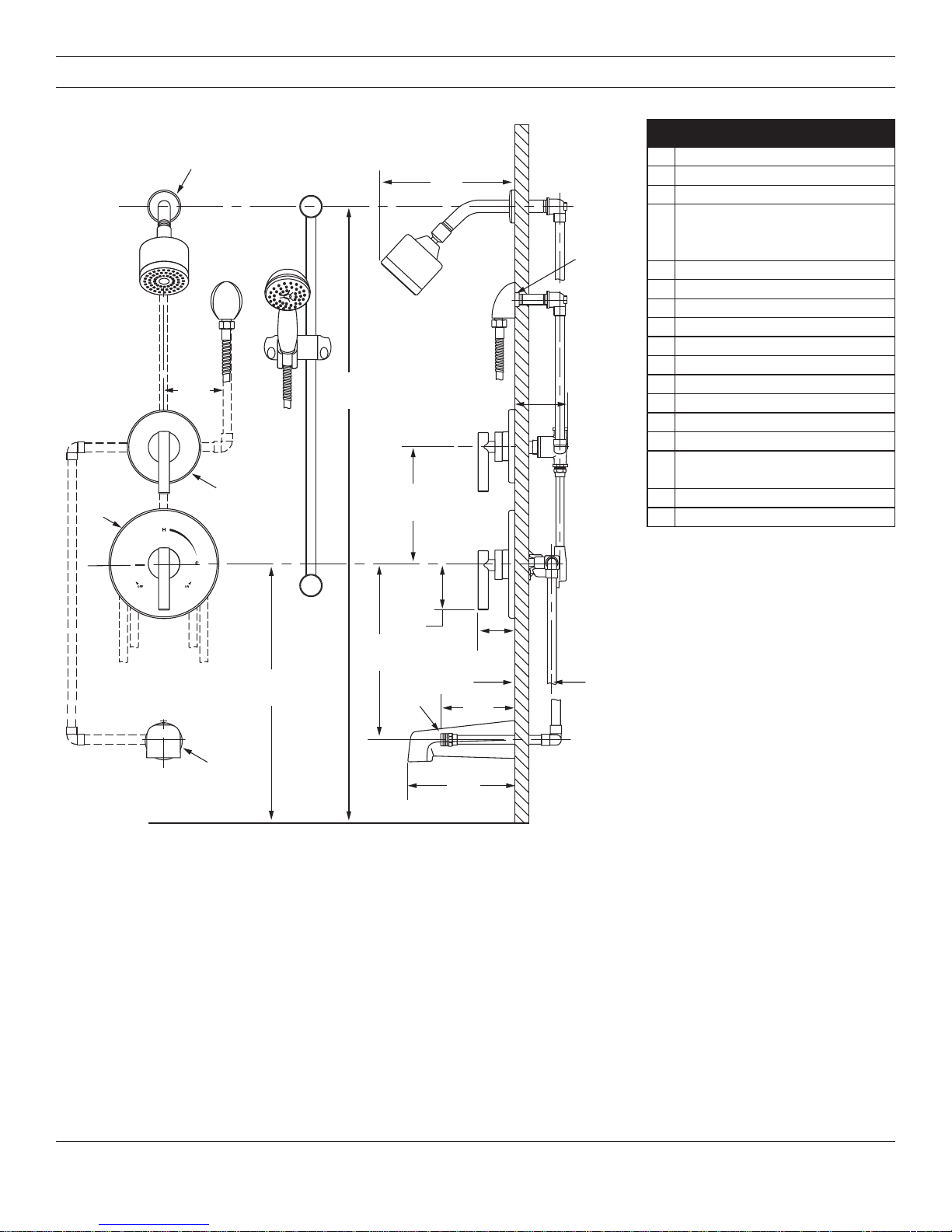
Dimensions
HH
CC
AA
GG
EE
JJ
BB
FF
DD
Measurements
A Ø 2-1/2", 64 mm
B 6-3/4", 171 mm
C 6", 152 mm
Male 1/2-14 NPT thread
D
must be recessed 1/4" (6 mm)
from finished wall
E Ref. 77", 1956 mm
F 4-3/4", 121 mm
G Ø 5", 127 mm
H Ø 7-1/2", 191 mm
I Ø 2-1/2", 64 mm
J Ref. 10", 254 mm
K Ref. 32", 813 mm
L Ref. 12", 305 mm
M 3", 76 mm
N 2-7/8", 73 mm
O
2-3/8" ± 1/2", 60 mm ± 13 mm
P 5-1/4", 133 mm
Q 7", 178 mm
Rough-in
MM
NN
KK
LL
RR
PP
II
QQ
FLOORFLOOR
Notes:
1) All dimensions measured from nominal rough-in (see O as reference).
2) Dimensions subject to change without notice.
OO
2
Page 3
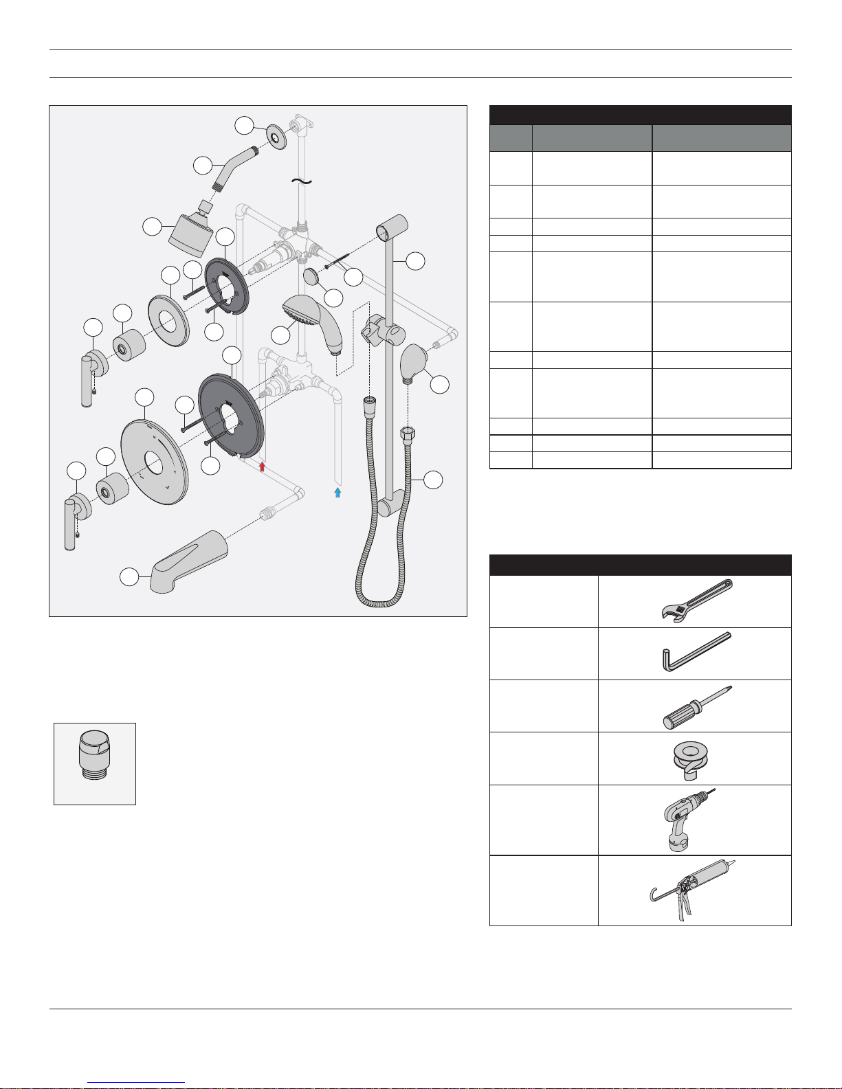
Parts Breakdown
C
Replacement Parts
Item Description Part Number
B
A
F
H
G
N
O
M
E
D
G
P
K
Q
I
J
E
D
J
HOT
Water Supply
COLD
Water Supply
R
A Showerhead 352SH
B
C
Shower Arm
Flange
300S
D Handle Assembly T-242A
E Dome Cover T-19/20
F
Diverter Escutcheon
G
H
I
J
K
Screws
Mounting Plate
Escutcheon
Screws
Mounting Plate
T-416A
RTS-009 (Brass)
RTS-010 (Plastic)
L Tub Spout 067
M
N
O
Slide Bar
Assembly
RA-009
P Hand Shower EF-100
Q Wall Elbow EF-105
R 60" Hose RTS-045
Notes:
1) Append appropriate -sufx for premium nish.
2) Append -1.5 or -2.0 to showerhead or hand
shower for low ow.
L
Notes:
1) Apply a bead of silicone around the perimeter of all shower trim
installed ush to the nished wall. Leave opening on bottom of
escutcheons for weep hole.
2) Apply plumber tape to all threaded connections.
*Order in-line vacuum breaker (EF-109) for hand
shower systems without dual checks.
EF-109*
Tools Required for Installation
Adjustable
wrench
Allen wrench:
Handle (2mm)
Phillips head
screwdriver
Plumber tape
Power drill
Silicone
3
Page 4

Installation
2
F
H
K
I
2
2
2
Note:
For valve body installation, please
see valve body installation guides.
1) Install small mounting plate (H)
to diverter valve (2DIV-BODY or
3DIV-BODY) and large mounting
plate (K) to shower valve (46-2BODY). Secure each with two
screws (G) and (J).
H
1
G
K
1
J
3) Attach shower escutcheon (I) to
large mounting plate (K).
Note: Tabs should snap into place.
4) Install dome covers (E) to valves by
turning clockwise.
E
1
5) Install diverter handle (3505 and
3506 only) (D) and shower
handle (D) to valves. Secure
handles by tightening set screws.
D
1
D
1
2) Attach diverter escutcheon (F) to
small mounting plate (H).
Note: Tabs should snap into place.
Note: Handles should be facing the
6 o'clock position.
6) Install tub spout (L) to stub out
pipe. Turn clockwise to secure.
1
1
E
L
4
Page 5

Installation
3
3
1
7a)
Dry Wall Option: R
and lower caps (M) from slide bar
brackets. Place slide bar (O) into
desired position. Using brackets
as a guide, carefully drill 3/16"
holes into wall. Remove slide bar
and install anchors.
emove upper
M
1
7b) Stud Option: R
lower caps (M) from slide bar
brackets. Place slide bar (O) into
desired position. Using brackets
as a guide, carefully drill 1/8"
pilot holes into stud.
emove upper and
M
1
8) With slide bar (O) in position,
secure to wall using screws (N).
Replace upper and lower caps (M)
onto slide bar brackets.
M
2
N
M
O
4
2
2
O
O
O
2
2
M
2
M
1
1
4
Notes: Make sure that slide bar
holes and bracket holes are aligned
before drilling. Before drilling bottom
hole, make sure slide bar is plumb.
Notes: Make sure that slide bar holes
and bracket holes are aligned before
drilling. Before drilling bottom hole,
make sure slide bar is plumb.
5
Page 6

Installation
4
2
2
2
9) Install wall elbow (Q) to stub
out pipe. Tighten set screw
to secure.
1
Q
10) Attach shower arm (B) and
ange (C) to vertical shower pipe
turning clockwise to tighten.
11) Install showerhead (A) to shower
arm (B). Turn clockwise to
tighten.
B
A
1
12) Attach large end of hand shower
hose (R) to hand shower wand
(P). Attach small end of hand
shower hose (R) to wall elbow
(Q). Turn clockwise to tighten.
P
1
R
Q
3
R
1
2
C
B
Operation (Temperature Control)
1) Turn shower handle counterclockwise approximately 1/4 turn
to put valve in cold position.
2) Turn shower handle counterclockwise approximately 1/2 turn
to put valve in warm position.
3) Turn shower handle counterclockwise approximately 3/4 turn
to put valve in hot position.
6
Page 7

Operation (Diverter Control: 2DIV-BODY)
1) Cartridge is factory set to divert
to function 1.
POSITION 1
Note: Additional handle positions for same output are illustrated.
2) Turn handle to position 2 to divert
to function 2.
POSITION 2
Operation (Diverter Control: 3DIV-BODY)
1) Cartridge is factory set to divert
to function 1.
POSITION 1
2) Turn handle to position 2 to divert
to function 2.
POSITION 2
3) Turn handle to position 3 to share
functions 1 and 2.
POSITION 3
3) Turn handle to position 3 to divert
to function 3.
POSITION 3
4) Turn handle to position 4 to share
functions 2 and 3.
POSITION 4
5) Turn handle to position 5 to share
functions 1 and 3.
POSITION 5
6) Turn handle to position 6 to share
functions 1 and 2.
POSITION 6
Troubleshooting Chart
Troubleshooting Chart
Clean nished trim area with a soft
Finish is spotting.
WARNING: This product can expose you to chemicals including lead, which is known to the state of California to
cause cancer, birth defects, or other reproductive harm. For more information, go to www.P65Warnings.ca.gov.
Elements in water supply may cause
water staining on nish.
cloth using mild soap and water or a
non-abrasive cleaner and then quickly
rinse with water.
Symmons Industries, Inc. ■ 31 Brooks Drive ■ Braintree, MA 02184 ■ Phone: (800) 796-6667 ■ Fax: (800) 961-9621
Copyright © 2018 Symmons Industries, Inc. ■ symmons.com ■ gethelp@symmons.com ■ ZV-3047 REV A ■ 081318
 Loading...