

Page 1
INSTALLATION OF:
58m m
67m m
SHOWER SYSTEMS AND
TUB/SHOWER SYSTEMS
Tools required for installation of this
product are: Phillips screw driver, tubing
cutter, Teflon tape, soldering equipment,
adjustable wrench and channel-lock pliers.
1. Install piping and fittings with valve
body as shown in Figure 2 or 3.
IMPORTANT: Valve rough-in is 2”
+/- 1/2” from CENTERLINE OF
SUPPLIES TO FACE OF FINISH
WALL. Install so that line indicated on
rough-in plaster shield (T-229) on valve
is flush with finish wall as shown in
Figure 1 (see Figure 5 for fiberclass wall
installation).
FIGURE 1
plaster shield
(T-229)
4" (101mm) Min
4 1/2" (114mm) Max
finish wall face
+
2" 1/2"
51mm
C
supplies
L
FIGURE 2
Model: C-96-2 Tub/Shower System
4 5/8"
116m m
approx.
40"
1016m m
7 3/8"
187m m
4"
102mm min.
5 1/2"
140mm min.
with stops
less stop s
6 1/2"
164m m
51m m
2"
Tub/Shower System (Figure 2)
Model C-96-2
Pipe shower head from outlet marked
“S” and to tub spout from outlet
marked “T”. The valve in this system has
a built-in choke for use with a diverter
spout. The built-in choke is designed so
that it cannot be subject to any back
pressure, other than is imposed by the
spout supplied with this package. DO
NOT SUBSTITUTE OTHER OUTLET
ACCESSORIES FOR THE TUB SPOUT
(SUCH AS HOSE AND SPRAY,
SHOWER HEAD, BODY SPRAY,
LEDGE SPOUTS, ETC.) OR ANY
PIPE ADAPTER OR ADDITIONAL
FITTINGS (SUCH AS PEX, ETC.)
THAT CAN CAUSE BACK PRESSURE
THROUGH THE VALVE. Install HOT
on left and COLD on right according to
valve markings.
Tub or Shower System (Figure 3)
Model C-96-1
Shower System: Pipe shower head
from outlet marked “S”. Install either
the included copper sweat or 1/2”-14
NPT plug (pipe sealer required) into the
outlet marked “T” (see figure 3A).
Tub only System: Pipe tub spout
from outlet marked “T”. Install either
the included copper sweat or 1/2”-14
NPT plug (pipe sealer required) into the
outlet marked “S” (figure 3A).
2. When finishing tile wall REMOVE (pull
off; don’t turn) ENTIRE PROTECTIVE
ROUGH-IN SHIELD and FILL AREA
AROUND VALVE BODY WITH GROUT
OR PLASTER.
3. TURN ON HOT AND COLD SUPPLIES,
valve will not operate unless both hot
and cold water are turned on.
2 1/4"
58m m
Suffix SS: Slip-on type spout
2 3/8"
2 1/4"
4. Tighten packing nut (T-17) for positive
frictional resistance to handle turn
throughout adjustment cycle and at
shut-off position. Check valve cap,
packing nut, all valve, pipe and fitting
connections for leaks.
5. SET LIMIT STOP SCREW AS DIRECTED
AFTER “IMPORTANT” IN BOLD TYPE ON
PAGE ONE. Attach dome cover (T-19)
onto packing nut (T-17) and secure
with lock nut (T-20).
6. ALLOW VALVE TO RUN IN WARM
POSITION FOR A FEW MINUTES TO
TOTALLY FLUSH SYSTEM. IF SYSTEM IS
Page 2

QUITE DIRTY, REMOVE VALVE SPINDLE
OR STOP SPINDLES (IF SO EQUIPPED)
TO INSURE PROPER FLUSHING. See
service instructions.
7. Push escutcheon (T-169) against
wall and secure to valve with two
escutcheon screws (DF-9B). Mount
temperature control handle (RC-14X)
on valve spindle spline as shown in
figure 9. Install shower arm, flange and
shower head. See Figures 2 and 3.
8. Do not install positive shut-off devices
on the outlet of this valve or devices
that do not allow the valve to flow at
least 1 GPM at 50 psi inlet pressure.
EXCEPTION: If a self-closing or slowclosing valve is installed on the outlet,
the supplies of the valve must be
equipped with checks to eliminate hot
to cold by-pass in the event the valve’s
handle is not turned to off after use.
Contact your factory representative or
Symmons directly for information on
available checks.
FIBERGLASS WALL INSTALLATION
When installing Temptrol® in fiberglass
or panel walls and it is desired to
sandwich wall between valve body
and escutcheon, cut hole in wall
as shown in Figure 5 and mount
valve with T-177 wall mounting
flange from rear. Note: It is always
recommended to secure valve
piping to rough construction and
not depend on fiberglass wall
for valve mounting security. On
panel walls over 1” thick, install in
conventional manner.
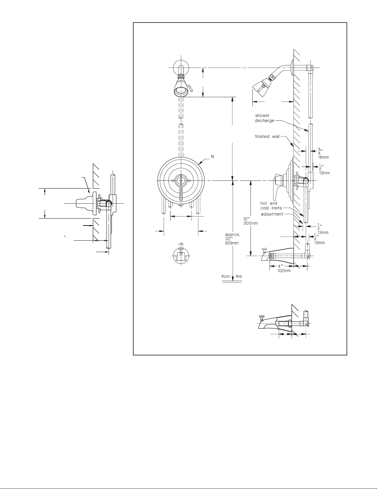
FIGURE 3
Model: C-96-1 Shower System
4 5/8"
116mm
approx.
24"
610mm
7 3/8"
187mm
4"
102mm min.
5 1/2"
140mm min.
with stops
less stops
approx.
48"
1219mm
floor line
6 1/2"
164mm
shower
discharge
finished wall
hot and
cold inlets
adjustment
2"
51mm
FIGURE 3A
5/8"
16mm
1/2"
13mm
1/2"
13mm
1/2"
13mm
Install plug here for
tub only installation
Copper sweat plug
or
1/2"-14 NPT plug
(pipe sealer required)
Install plug here for
shower only installation
FIGURE 5
T-177 Wall Mounting Flange
13
''
For 21mm to 1" 25mm
16
thick wall order part no. T-193
1
to
'' 2mm
16
THICK WALL
FG Wall Mounting
Flange
3
'' 19mm
4
HOLE SIZE
4" (101mm) Min
4 1/2" (114mm) Max
Page 3

BACK TO BACK INSTALLATION
B
HOT
COLD
COLD
HOT
To simplify piping on back to back installations use one standard valve (hot on left, cold on right) and one with reverse
coring (hot on right, cold on left) as shown in Figure 6 and
7. Order reverse core valve by adding the suffix REV-X
after the plate number. (e.g. C-96-2-REV-X Temptrol
®
tub and
shower unit with reverse coring.)
FIGURE 6
FIGURE 7
Back to Back Installation
1
6
''
4
159mm
MINIMUM WALL
3
1
+
''
4
shower
discharge
''
2
2
70mm 13mm
finished wall
THICKNESS
1
2
13mm
''
OPERATION OF VALVE
The main handle of the Temptrol® valve is for control of
temperature only. From the OFF position, the handle is
turned counter-clockwise through a minimum cold position,
through a warm and hot position for a maximum turn of
approximately one revolution. This allows for wide range of
temperature adjustments to suit the requirements of any user.
CARE AND CLEANING
The lustrous finish on your Temptrol valve should be treated
with care. It can be readily damaged by improper handling or
abusive treatment. To clean the finish wipe gently with a soft
damp cloth and blot dry with a soft towel. Use only a mild
soap solution if required. DO NOT USE ABRASIVE CLEAN-
ERS. USE OF POLISH, ABRASIVE CLEANERS, SOLVENTS
OR ACID CLEANERS WILL DAMAGE THE FINISH AND
VOID THE SYMMONS WARRANTY.
STANDARD
VALVE
hot and cold
inlets
1
+
''
''
2
51mm 13mm
2
57mm 13mm
2
1
1
+
''
''
4
2
tub discharge
FIGURE 8
Seat Removal Tools
FOUR BROACHED
NOTCHES TO
ENGAGE FOUR
CORNERS
OF HOT SEAT
TOOL.
NOTCH
T-35A
COLD
REVERSE
CORE VALVE
T-35
EIGHT BROACHED NOTCHES
TO ENGAGE FOUR CORNERS
OF COLD SEAT TOOL IN TWO
POSITIONS.
Page 4

INDIVIDUAL PARTS COMPOSITE PARTS
DF-9B Escutcheon screws (2)
DF-9CVP Escutcheon screws
(vandal-resistant) (2)
RC-14X Single blade lever handle
SC-15A Set screw
T-1 Hot renewable seat
T-2 Cold seat O-ring
T-3 Cold renewable seat
T-5 Hot washer screw
T-6 Hot washer
T-7 Cold washer retainer
T-8 Cold washer
TA-10 Flow control spindle
T-11 Cap gasket
T-12A Cap assembly
T-16 Packing, O-ring and washers
T-17 Packing nut
T-19BR Dome cover
T-20 Lock nut
T-34 Limit stop with O-ring
T-35A Hot seat removal tool
T-35B Cold seat removal tool
T-52A Stop spindle assembly/
escutcheon screw retainer
T-55B Stop plaster shield
T-55C Stop plaster shield removal
tool
T-169 Escutcheon
T-177 Wall mounting flange
T-229 Plaster shield with clip
T-52 Stop spindle assembly/
escutcheon screw retainer
(T-52A)
Stop plaster shield (T-55B)
TA-4 Hot seat (T-1)
Cold seat (T-3)
Cold seat O-ring (T-2)
TA-9 Hot washer screw (T-5)
Hot washer (T-6)
Cold washer retainer (T-7)
Cold washer (T-8)
Cap gasket (T-11)
TA-10 Spindle assembly
T-19/20-PL Dome cover (T-19BR)
Lock nut (T-20)
FIGURE 9
Parts Breakdown
T-52A
T-55B
T- 52
T-177
T- 35A
T- 1 T- 2 T- 3 T- 5 T- 6 T- 7
TA-4 TA-9
T- 229
TO BE DISCARDED
BEFORE INSTALLING
TRIM
INCLUDES T-11
T- 35B
T- 8
TA-10 T- 11 T- 16
T- 55C
T- 169
T- 34
T- 12A
DF-9B
DF-9CVP
T- 17
T- 20 T- 19BR
T- 19/20-PL
SC-15A
RC-14X
Page 5

TROUBLESHOOTING CHART
1. Shut off water supply to valve.
2. Remove handle plug button (T-33) and
handle (T-31).
3. Remove dial [T-29(A,B,C)] and escutch-
eon (T-27) by removing escutcheon
screws (T-28). Remove all remaining trim.
4. Open valve to about warm position
and unscrew cap (T-12A). Warning:
Failure to do this will damage cap and
spindle. Spindle assembly (TA-10) will
be removed with cap. Leave packing
nut (T-17) in place while unscrewing
cap to avoid distortion.
5. Ordinary service to eliminate drip-
ping or not shutting off requires only
the replacement of parts supplied in
washer and gasket kit (TA-9). Hold
spindle with (T3-31) handle while
removing hot washer screw and cold
washer retainer (remove retainer with
channel lock pliers).
6. Inspect top surfaces of hot and cold
seats and replace if necessary. Impor-
tant: When replacing hot and cold
seats, always replace both seats. Even if
only one seat appears worn, both seats
must be replaced. Use part No. (TA-4).
After long years of service, if spindle
is very loose in cold seat, replace with
part no. (TA-4). Use seat removal tool
[T-35(A,B)] for removal and replace-
ment of (TA-4). If seats are difcult
to remove and tool shifts damaging
notches, relocate tool in second posi-
tion of notches. Tighten both seats to
15 foot pounds of torque.
7. The perforated end of the (TA-10)
spindle assembly houses the balancing
piston which is the heart of this pres-
sure balancing valve. The piston should
be free to move back and forth and
should click when the spindle assembly
is shaken. If deposits block this action,
tap the handle end of the spindle
against a solid object to free the piston.
Soaking in household vinegar will
help free foreign matter. If this does
not free piston, replace (TA-10) spindle
assembly. DO NOT TAMPER WITH
PERFORATED CYLINDER ON THE
SPINDLE ASSEMBLY OR ATTEMPT
REMOVAL OF THE PISTON.
8. Reassemble, reversing above pro-
cedure, be sure spindle assembly is
drawn close to the cap before screw-
ing cap back into valve. WARNING:
FAILURE TO DO THIS WILL DAMAGE
CAP AND SPINDLE.
9. USE ONLY SYMMONS GENUINE REPAIR
PARTS. FAILURE TO DO SO WILL VOID
ALL WARRANTIES AND IMPAIR PROPER
OPERATION OF YOUR VALVE.
TEMPTROL® SERIES SERVICE INSTRUCTIONS
SERVICE
1. Shut off water supply to valve or close
valve integral screw driver stops by turning in clockwise direction after step 3.
2. Loosen set screw (SC-15A) and remove
handle (RC-14X) (see figure 9).
3. Remove escutcheon (T-169) by removing
escutcheon screws (DF-9B). Remove all
remaining trim.
4. Open valve to about warm position
and unscrew cap (T-12A). Warning:
Failure to do this will damage cap and
spindle. Spindle assembly (TA-10) will
be removed with cap. Leave packing
nut (T-17) in place while unscrewing
cap to avoid distortion.
5. Ordinary service to eliminate dripping or not shutting off requires only
the replacement of parts supplied in
washer and gasket kit (TA-9). Hold
spindle with handle while removing
hot washer screw and cold washer
TROUBLE SHOOTING CHART
Problem Cause Solution (Follow service instructions)
Valve will not pass water. Hot and cold water not turned on. Turn on both supplies. Valve will not operate
Valve leaks when shut off. Hot and cold washers are worn, or foreign
retainer (remove retainer with channel
lock pliers).
6. Inspect top surfaces of hot and cold
seats and replace if necessary. Important: When replacing hot and cold
seats, always replace both seats. Even if
only one seat appears worn, both seats
must be replaced. Use part No. (TA-4).
After long years of service, if spindle
is very loose in cold seat, replace with
part no. (TA-4). Use seat removal tool
[T-35(A,B)] for removal and replacement
of (TA-4). If seats are difficult to remove
and tool shifts damaging notches, relocate tool in second position of notches.
Tighten both seats to 15 foot pounds of
torque.
7. The perforated end of the (TA-10)
spindle assembly houses the balancing
piston which is the heart of this pressure
balancing valve. The piston should be
matter (solder, chips, etc.) are between washers
and seat surfaces
free to move back and forth and should
click when the spindle assembly is
shaken. If deposits block this action, tap
the handle end of the spindle against a
solid object to free the piston. Soaking
in household vinegar will help free foreign matter. If this does not free piston,
replace (TA-10) spindle assembly. DO
NOT TAMPER WITH PERFORATED
CYLINDER ON THE SPINDLE ASSEMBLY OR ATTEMPT REMOVAL OF THE
PISTON.
8. Reassemble, reversing above procedure,
be sure spindle assembly is drawn close
to the cap before screwing cap back
into valve. Warning: Failure to do this
will damage cap and spindle.
9. Use only Symmons Genuine Repair
Parts. FaIlure to do so will void all warranties AND IMPAIR PROPER OPERATION
OF YOUR VALVE.
unless both HOT and COLD water pressure is
turned on.
Replace Hot and Cold washers, inspect top
surface on hot and cold seats and replace if
necessary.
Temperature control handle is turned from
cold to hot (or hot back to cold) and volume
from spout or head is not constant.
Valve delivers sufcient quantity of cold, but
little hot, or the reverse of this.
Temperature varies without moving handle. Same as above Same as above
Valve delivery temperature reduces gradually
during use; must be turned on to hotter positions to maintain constant temperature.
Valve delivers hot water when initially opened
and water turns colder when the handle is
rotated in a counter-clockwise direction.
In tub/shower valves, when diverter is set in
shower position a trickle of water runs from
tub spout.
Pressure balancing piston housed in spindle
assembly is blocked from free movement by
foreign matter.
Same as above Same as above
Overdraw on hot water supply, i.e., running
out of hot water.
Valve is piped incorrectly, i.e., the hot supply is
piped to the cold inlet to the valve and the cold
supply is piped to the hot inlet of the valve.
A design function of this valve is to allow
a trickle of water from the tub spout when
diverter is set for shower position, This trickle of
water is necessary to ensure safe operation in
that the valve will be shut off at main handle
and NOT with diverter handle.
With valve open half way, remove handle and
tap spindle with plastic hammer. If problem
not solved, remove spindle assembly completely and tap handle against solid object to
free piston. Soaking in household vinegar will
help free foreign matter.
Reduce maximum ow by using volume
control adjustment on valve or shower head.
This will allow longer period of use before
overdrawing hot water supply.
If piping is accessible, correct piping connections to the valve. If piping is not accessible,
contact factory to order a reverse seat and
tool (T-108 KIT). Older installations may require
replacement of the hot seat (T-1) as well
Symmons Industries, Inc. ■ 31 Brooks Drive ■ Braintree, MA 02184
(800) 796-6667, (781) 848-2250
Website: www.symmons.com
■ Fax (800) 961-9621, (781) 843-3849
■ Email: customerservice@symmons.com
©2007, 2008 Symmons Industries, Inc. Printed in U.S.A.
■ ZV-459 ■ 071211
Page 6

onic
and
onic
defects
At
or
any
damage
this
oduct
of
or
this
AND
OF
an
not
A
please
oblem,
Temptrol
®
Commercial Series Pressure-Balancing Mixing Valve for Shower or Tub/Shower Application
INSTALLATION, OPERATION & SERVICE INSTRUCTIONS
Symmons valves and shower heads comply to all known standards, codes and
specifications: CSA B-125, ANSI A112.18.1M, ASSE 1016, EPA ‘92 etc.
Symmons shower heads are equipped with a 2.5 GPM (9.5 L/min) water and energy
saving flow restrictor.
COMMERCIAL LIMITED WARRANTY
Symmons warrants to the original purchaser that any Symmons product (excluding Symmons electr
products) when used in industrial, commercial or business use will be free of defects in material
workmanship during normal use for a period of 5 years from the date of purchase. Symmons electr
products (excluding batteries) when used in industrial, commercial or business use will be free of
in material and workmanship during normal use for a period of 3 years from the date of purchase.
our option, we will either have you send the defective part or product prepaid to us for inspection,
we may elect to send you the replacement part or product without investigation. A replacement for
defective part will be supplied FREE OF CHARGE for installation by the purchaser. Defect or
caused by the use of replacement parts other than Symmons Genuine Replacement Parts will void
warranty. This warranty excludes product damage due to installation error, product abuse, or pr
misuse whether performed by a contractor, service company or yourself.
Damage to the chrome and/or other decorative finishes on Symmons products may be a result
improper handling or abusive treatment. Finishes should only be cleaned with a soft, damp cloth
sponge. Use of polish, abrasive cleaners, solvents, or acid cleaners will damage the finish and void
warranty.
There are no other express warranties on this product and ALL WARRANTIES OF MERCHANTABILITY
OTHER IMPLIED WARRANTIES ARE LIMITED IN ACCORDANCE WITH APPLICABLE LAW. SYMMONS
INDUSTRIES, INC., EXPRESSLY DISCLAIMS CONTINGENT LIABILITY AND CONSEQUENTIAL DAMAGE
EVERY KIND. Since some states do not allow limitations on how long an implied warranty lasts or
exclusion or limitation of incidental or consequential damages the above limitation or exclusion may
be applicable. This warranty gives specific legal rights. Other rights may vary from state to state.
To obtain warranty service, write to Symmons Industries, Inc., 31 Brooks Drive, Braintree, M
02184-3804 or call our Customer Service Department at 1-800-SYMMONS. If writing to us,
include proof of purchase, the model number of the product with a brief description of the pr
your name, address and phone number.
IMPORTANT: After completion of installation step 4, follow these instructions to set
the Temptrol Limit Stop Screw. This valve is equipped with a limit stop screw to be
used to limit valve handle from being turned to excessively hot water discharge temperatures. To adjust, remove dome cover, open valve to maximum desired temperature and turn in limit stop screw until it seats.
WARNING: FAILURE TO AdjUST ThE LIMIT STOP SCREW PROPERLy MAy RESULT
IN SERIOUS SCALdING.
WARNING: ThIS ShOWER SySTEM MAy NOT PROTECT ThE USER FROM SCALdING WhEN ThERE IS A FAILURE OF OThER TEMPERATURE CONTROLLING
dEVICES ELSEWhERE IN ThE PLUMbING SySTEM.
PLEASE REAd ALL INSTRUCTIONS CAREFULLy bEFORE STARTING
INSTALLATION. SAVE ThIS MANUAL FOR FUTURE REFERENCE.
 Loading...