

Page 1

7-225, 7-230 Series
Maxline
Operation & Maintenance Manual
Model Numbers
7-225-CK-MS
7-225-CK-F
7-225-CK-PEX
7-230-CK-M
7-230-CK-FS
Modifications
-B
-NI
-T
-W
-X
Wall cabinet in white enamel finish
including wall mounting bracket
Nickel plated
Stainless steel cabinet in place of
standard white cabinet
Wall mounting bracket
Separate Stops (7-225-CK-MS only)
Connections: 1/2” male NPT
1/2” female sweat
Connections: 1/2” female NPT
Connections: 1/2” PEX
Connections: 3/4” male NPT
Connections: 3/4” female sweat
Specification
Water temperature limiting valve including integral
checks and dual stainless steel strainers for double
protection against suspended particles in supply
lines. Valve made from lead free* metal components
(see table 1 for ow rates).
Temperature control range:
60°F - 140°F (15.6°C - 60°C)
Minimum supply pressure: 20 psi (138 kPa)
Maximum supply pressure: 125 psi (862 kPa)
Inlet to outlet temperature differential: 10°F (5.55°C)
*According to US Senate bill S.3874, the term “lead free” is dened as
follows: “not more than a weighted average of 0.25 percent lead when
used with respect to the wetted surfaces of pipes, pipe ttings, plumbing
ttings, and xtures”
Compliance
-ASME A112.18.1; CSA B125.1
Note: Append appropriate -sufx to model number.
Warranty
5 Years - for commercial installations.
Refer to www.symmons.com/warranty for complete
warranty information.
Valve Model
7-225-CK-MS
7-225-CK-F
7-225-CK-
PEX
7-230-CK-M
7-230-CK-FS
1
Size
Connection
1/2” Male NPT
1/2” Female Sweat
(13 mm)
1/2” Female NPT
(13 mm)
1/2” PEX
(13 mm)
3/4” Male NPT
(19 mm)
3/4” Female Sweat
(19 mm)
Symmons Industries, Inc. ■ 31 Brooks Drive ■ Braintree, MA 02184 ■ (800)796-6667 ■ Fax: (800)961-9621
©2014 Symmons Industries, Inc.■ www.symmons.com ■ gethelp@symmons.com ■ ZV-3009 REV D 05/27/14
Min. Flow Rate
0.5 gpm
(1.9 L/min)
0.5 gpm
(1.9 L/min)
0.5 gpm
(1.9 L/min)
0.5 gpm
(1.9 L/min)
0.5 gpm
(1.9 L/min)
-ASSE 1017; CSA B125.3
-ASSE 1070; CSA B125.3
-CA 116875 (AB 1953)
-NSF/ANSI 61.9; NSF/ANSI 372
-US S.3874
Table 1: Flow Rate - gpm (L/min)
Pressure Differential - psi (kPa)
5 psi
(34 kPa)
4.5 gpm
(17.1 L/min)
4.5 gpm
(17.1 L/min)
3.5 gpm
(13.3 L/min)
5.0 gpm
(19.0 L/min)
5.0 gpm
(19.0 L/min)
10 psi
(69 kPa)
7.0 gpm
(26.6 L/min)
7.0 gpm
(26.6 L/min)
5.5 gpm
(20.9 L/min)
7.0 gpm
(26.6 L/min)
7.0 gpm
(26.6 L/min)
(138 kPa)
9.5 gpm
(36.1 L/min)
9.5 gpm
(36.1 L/min)
8.0 gpm
(30.4 L/min)
10.0 gpm
(38.0 L/min)
10.0 gpm
(38.0 L/min)
20 psi
25 psi
(172 kPa)
10.5 gpm
(39.9 L/min)
10.5 gpm
(39.9 L/min)
8.5 gpm
(32.3 L/min)
11.0 gpm
(41.8 L/min)
11.0 gpm
(41.8 L/min)
30 psi
(207 kPa)
12.0 gpm
(45.6 L/min)
12.0 gpm
(45.6 L/min)
9.5 gpm
(36.1 L/min)
12.0 gpm
(45.6 L/min)
12.0 gpm
(45.6 L/min)
c
45 psi
(310 kPa)
14.0 gpm
(53.2 L/min)
14.0 gpm
(53.2 L/min)
12.0 gpm
(45.6 L/min)
14.0 gpm
(53.2 L/min)
14.0 gpm
(53.2 L/min)
Page 2
7-225, 7-230 Series
Maxline
Operation & Maintenance Manual
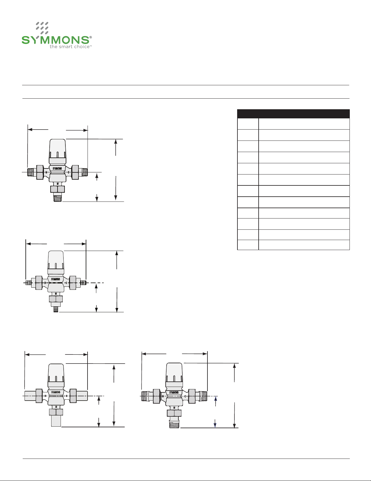
Dimensions
7-225-CK-MS
A
7-225-CK-PEX
D
C
B
E
Measurements
A 6 7/16”, 164 mm
B 6 9/16”, 167 mm
C 3 1/8”, 79 mm
D 6 3/4”, 171 mm
E 6 11/16”, 170 mm
F 3 1/4”, 83 mm
G 7”, 178 mm
H 6 13/16”, 173 mm
I 3 3/8”, 86 mm
J 7”, 178 mm
K 6 13/16”, 173 mm
L 3 3/8”, 86 mm
F
7-225-CK-F, 7-230-CK-FS 7-230-CK-M
G
H
I
Note: Dimensions are subject to change without notice.
2
Symmons Industries, Inc. ■ 31 Brooks Drive ■ Braintree, MA 02184 ■ (800)796-6667 ■ Fax: (800)961-9621
©2014 Symmons Industries, Inc.■ www.symmons.com ■ gethelp@symmons.com ■ ZV-3009 REV D 05/27/14
J
K
L
Page 3

7-225, 7-230 Series
Maxline
Operation & Maintenance Manual
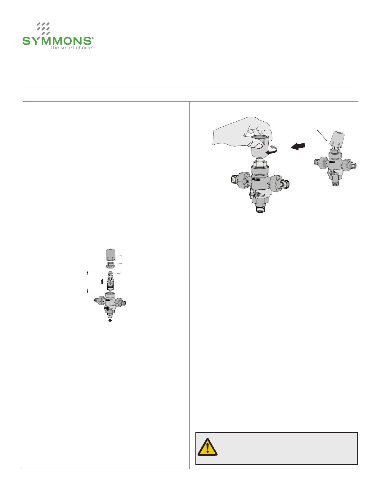
Parts Breakdown
7-225 Series 7-230 Series
Safety cap
in temperature
adjust position
G
H
D
E
F
E F G
A
B
C
D
E
F
G
Safety cap
in temperature
adjust position
E
F
G
D
A
B
C
D
E F
E
F
Replacement Parts 7-225 Series
Item Description Part No.
A Safety cap TMX-277
B Cap retainer TMX-269
C Cartridge TMX-267-KIT
D Check valve TMX-274-KIT
E
F
G
H Wall hanger TMX-290-KIT
3
1/2” PEX union
tting kit
1/2” female
union tting kit
1/2” male union
tting kit
Symmons Industries, Inc. ■ 31 Brooks Drive ■ Braintree, MA 02184 ■ (800)796-6667 ■ Fax: (800)961-9621
©2014 Symmons Industries, Inc.■ www.symmons.com ■ gethelp@symmons.com ■ ZV-3009 REV D 05/27/14
TMX-289-LL-KIT
TMX-293-LL-KIT
TMX-286-LL-KIT
Replacement Parts 7-230 Series
Item Description Part No.
A Safety cap TMX-277
B Cap retainer TMX-269
C Cartridge TMX-267-KIT
D Check valve TMX-274-KIT
E
F
G Wall hanger TMX-290-KIT
3/4” female
union tting kit
3/4” male
union tting kit
TMX-288-LL-KIT
TMX-287-LL-KIT
Page 4
7-225, 7-230 Series
Maxline
Operation & Maintenance Manual
Installation
Sizing Valve
For assistance in sizing and selection of the proper
valve, consult your local representative or Symmons
Customer Service.
Installing Valve
1) Flush piping thoroughly prior to installing.
2) Install valve so as to allow clearance for replacing
cartridge. Valve can be installed in any orientation.
3) Connect valve input/ouput to supply ports.
a. Hot port marked (H)
b. Cold port marked (C)
c. Mixed output port marked (M)
protective cap
retaining nut
cartridge
Valve
clearance
4"
102 mm
Protective Cap
Temperature
Adjust
4) Place thermometer in the outlet stream. Measure
and accurately set temperature. Inlet temperature
must be ± 10°F (5.55°C) of desired output.
5) To increase temperature turn safety cap
counter-clockwise. To decrease temperature turn
safety cap clockwise.
(H) HOT
supply port
(M) MIXED
output port
(C) COLD
supply port
Setting Valve Temperature
1) Turn hot and cold water supply on.
2) Open faucet to allow hot water to ow for a
minimum of one minute. For two handle faucets
turn on hot water only. For single handle faucets
turn on to the hot position.
3) Remove the safety cap by inserting a small at
tip screw driver into the wide slot at the base of
the cap and pry upward, then ip the safety cap
over 180 degrees and t onto the end of valve
spindle.
4
Symmons Industries, Inc. ■ 31 Brooks Drive ■ Braintree, MA 02184 ■ (800)796-6667 ■ Fax: (800)961-9621
©2014 Symmons Industries, Inc.■ www.symmons.com ■ gethelp@symmons.com ■ ZV-3009 REV D 05/27/14
For single temperature applications adjust valve
outlet temperature with full ow of tempered
water from tting.
For dual temperature applications open
approximately 50% of all faucets to their full hot
position to ensure proper operating temperature
at peak demand.
6) Remove safety cap from end of valve spindle and
ip over 180 degrees, then press cap down and
snap back onto valve body to replace.
Note: Once the safety cap is snapped onto the
valve body the outlet temperature cannot be
changed without repeating steps 2-6.
Warning: Water temperatures in excess of
110°F (43°C) may cause scalding or
severe injury!
Page 5
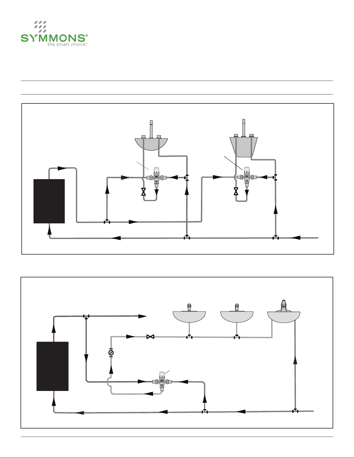
HOT
WATER
TANK,
HEATER,
ETC.
Main hot supply
Cold supply
Lavatory
faucet
Tub
valve
(V1)
valve
(V2)
MAXLINE
valve
MAXLINE
valve
Tempered
hot supply
Tempered
hot supply
7-225, 7-230 Series
Maxline
Operation & Maintenance Manual
Installation
Point of Use Diagram
Multiple Fixtures Diagram
5
High temperature hot supply
(if required for laundry, etc.)
HOT
WATER
TANK,
HEATER,
ETC.
Symmons Industries, Inc. ■ 31 Brooks Drive ■ Braintree, MA 02184 ■ (800)796-6667 ■ Fax: (800)961-9621
©2014 Symmons Industries, Inc.■ www.symmons.com ■ gethelp@symmons.com ■ ZV-3009 REV D 05/27/14
Thermometer
recommended
valve
Single supply faucets
Tempered hot supply
MAXLINE
valve
Two supply faucet
Cold supply
Page 6

7-225, 7-230 Series
Maxline
Operation & Maintenance Manual
Operation & Maintenance
Initial 30 Day Inspection
Inspect cartridge within 30 days of initial operation.
If inspection determines that your water system is
causing deposits and foreign matter to build-up,
then adjust cartridge maintenance accordingly.
Cartridge Replacement
1) Shut off hot and cold water supplies to valve.
2) Remove safety cap by inserting a small
screwdriver into the widest opening at the base
of the cap and pry upward. This will expose the
cartridge stem and cartridge retaining unit.
3) Remove retaining nut by turning counter-clockwise
with adjustable wrench. Grasp cartridge with
pliers and remove from body by pulling straight
out. A slight rocking rotation may be required to
loosen while removing.
on front of valve casting as shown below to the
left. Install retaining nut back onto valve body.
5) Refer to “Setting Valve Temperature” section (pg.4)
to properly set valve to desired temperature.
Service Instructions
Cleaning or replacing lter washer and check valve:
1) Remove union adapter nut from valve body and
then valve tting from union adapter.
2) Clean lter washer seated in valve tting by
soaking both in household vinegar and rinse under
running water. Ensure not to damage screen in
lter washer.
3) Replace lter washer into center of valve tting.
4) Replace check valve by removing from center of
valve body port connection.
4) Lubricate cartridge o-rings with a small amount of
lubricant prior to reinstalling. Insert replacement
cartridge into valve body, applying enough force to
ensure cartridge is fully seated. Install cartridge
with keyway inline with Symmons logo located
retaining nut
Torque to 132 inch lbs. (15Nm)
6
Symmons Industries, Inc. ■ 31 Brooks Drive ■ Braintree, MA 02184 ■ (800)796-6667 ■ Fax: (800)961-9621
©2014 Symmons Industries, Inc.■ www.symmons.com ■ gethelp@symmons.com ■ ZV-3009 REV D 05/27/14
5) Fasten and tighten union adapter nut over valve
tting to valve body.
Seasonal Use
If valve is used seasonally, such as in schools or
campgrounds, then perform the following steps to
avoid damage caused by freezing water when valves
are not in use:
1) Shut off hot and cold water supplies.
2) Remove valve cartridge and drain all water.
3) Drain water from the supply lines and valve body.
Page 7

7-225, 7-230 Series
Maxline
Operation & Maintenance Manual
Care and Cleaning
Remove cartridge and clean valve body in household vinegar to remove corrosive mineral build up. Rinse
under running hot water to ensure valve is free of foreign debris.
Trouble Shooting Chart
Problem Cause Solution
1) Remove lter washer and clean
under running water or replace by
ordering check valve/union tting
Water ow is less than normal.
Screen in valve is dirty or cartridge
is dirty or clogged.
2) Remove cartridge and clean in
household vinegar or replace by
ordering cartridge replacement kit.
replacement kit.
Valve is leaking around the cap
retaining nut area.
Tempered hot water temperature
is not hot enough.
Water leaking from o-ring seal.
Hot water supply into valve is not
10°F (5.55°C) above desired set
point temperature.
Replace o-ring by ordering
cartridge replacement kit.
Increase hot water supply
temperature into valve.
7
Symmons Industries, Inc. ■ 31 Brooks Drive ■ Braintree, MA 02184 ■ (800)796-6667 ■ Fax: (800)961-9621
©2014 Symmons Industries, Inc.■ www.symmons.com ■ gethelp@symmons.com ■ ZV-3009 REV D 05/27/14
Page 8

Serie 7-225, 7-230
Maxline
Manual de funcionamiento y mantenimiento
Números de modelo
7-225-CK-MS
7-225-CK-F
7-225-CK-PEX
7-230-CK-M
7-230-CK-FS
Conexiones: NPT macho de 1/2”
hembra de 1/2” de cobre
Conexiones: NPT hembra de 1/2”
Conexiones: PEX de 1/2”
Conexiones: NPT macho de 3/4”
Conexiones: Hembra de 3/4”
de cobre
Modificaciones
-B
-NI
-T
-W
-X
Gabinete de pared en acabado de
esmalte blanco que incluye soporte
de montaje en pared
Chapado en níquel
Gabinete de acero inoxidable
Soporte de montaje en pared
De servicio independiente detiene
(7-225-CK-MS)
Especificación
La válvula limitadora de temperatura del agua que
incluye válvulas antirretorno integrales y dos tamices
de acero inoxidable para una doble protección contra
partículas en suspensión en las líneas de suministro.
Válvula fabricada con componentes metálicos libres
de plomo* (ver la tabla 1 para informarse sobre las
tasas de ujo).
Rango de control de temperatura:
60 °F - 140 °F (15,6 °C - 60 °C)
Presión mínima de suministro: 20 psi (138 kPa)
Presión máxima de suministro: 125 psi (862 kPa)
Diferencial de temperatura entre
entrada y salida: 10 °F (5,55 °C)
*De acuerdo con el proyecto de ley del Senado de los EE.UU. S.3874,
el término “libre de plomo” se dene de la siguiente manera: “no más
que un promedio ponderado de 0,25 por ciento de plomo cuando se
utiliza con respecto a las supercies húmedas de tuberías, accesorios de
tubería, accesorios de fontanería y artefactos”
Cumplimiento
-ASME A112.18.1; CSA B125.1
Nota: Anexe el sujo apropiado al número del modelo.
Garantía
5 años - para instalaciones comerciales.
Consulte www.symmons.com/warranty para obtener
información completa sobre la garantía.
Tabla 1: Tasa de ujo - gpm (L/min)
Modelo de
válvula
7-225-CK-MS
7-225-CK-F
7-225-CK-
PEX
7-230-CK-M
7-230-CK-FS
8
Tamaño
Conexión
NPT macho de 1/2”
Hembra de 1/2” de
cobre (13 mm)
NPT hembra de 1/2”
(13 mm)
PEX de 1/2”
(13 mm)
NPT macho de 3/4”
(19 mm)
Hembra de 3/4” de
cobre (19 mm)
Symmons Industries, Inc. ■ 31 Brooks Drive ■ Braintree, MA 02184 ■ (800)796-6667 ■ Fax: (800)961-9621
©2014 Symmons Industries, Inc.■ www.symmons.com ■ gethelp@symmons.com ■ ZV-3009 REV D 05/27/14
Tasa de ujo
mín.
0.5 gpm
(1,9 L/min)
0.5 gpm
(1,9 L/min)
0.5 gpm
(1,9 L/min)
0.5 gpm
(1,9 L/min)
0.5 gpm
(1,9 L/min)
(17,1 L/min)
(17,1 L/min)
(13,3 L/min)
(19,0 L/min)
(19,0 L/min)
5 psi
(34 kPa)
4.5 gpm
4.5 gpm
3.5 gpm
5.0 gpm
5.0 gpm
-ASSE 1017; CSA B125.3
-ASSE 1070; CSA B125.3
-CA 116875 (AB 1953)
-NSF/ANSI 61.9; NSF/ANSI 372
-US S.3874
Diferencial de presión - psi (kPa)
10 psi
(69 kPa)
7.0 gpm
(26,6 L/min)
7.0 gpm
(26,6 L/min)
5.5 gpm
(20,9 L/min)
7.0 gpm
(26,6 L/min)
7.0 gpm
(26,6 L/min)
20 psi
(138 kPa)
9.5 gpm
(36,1 L/min)
9.5 gpm
(36,1 L/min)
8.0 gpm
(30,4 L/min)
10.0 gpm
(38,0 L/min)
10.0 gpm
(38,0 L/min)
(39,9 L/min)
(39,9 L/min)
(32,3 L/min)
(41,8 L/min)
(41,8 L/min)
25 psi
(172 kPa)
10.5 gpm
10.5 gpm
8.5 gpm
11.0 gpm
11.0 gpm
30 psi
(207 kPa)
12.0 gpm
(45,6 L/min)
12.0 gpm
(45,6 L/min)
9.5 gpm
(36,1 L/min)
12.0 gpm
(45,6 L/min)
12.0 gpm
(45,6 L/min)
c
45 psi
(310 kPa)
14.0 gpm
(53,2 L/min)
14.0 gpm
(53,2 L/min)
12.0 gpm
(45,6 L/min)
14.0 gpm
(53,2 L/min)
14.0 gpm
(53,2 L/min)
Page 9

Serie 7-225, 7-230
Maxline
Manual de funcionamiento y mantenimiento
Dimensiones
7-225-CK-MS
A
7-225-CK-PEX
D
C
B
E
Mediciones
A 6 7/16”, 164 mm
B 6 9/16”, 167 mm
C 3 1/8”, 79 mm
D 6 3/4”, 171 mm
E 6 11/16”, 170 mm
F 3 1/4”, 83 mm
G 7”, 178 mm
H 6 13/16”, 173 mm
I 3 3/8”, 86 mm
J 7”, 178 mm
K 6 13/16”, 173 mm
L 3 3/8”, 86 mm
F
7-225-CK-F, 7-230-CK-FS 7-230-CK-M
G
H
I
Nota: Las dimensiones pueden cambiar sin previo aviso.
9
Symmons Industries, Inc. ■ 31 Brooks Drive ■ Braintree, MA 02184 ■ (800)796-6667 ■ Fax: (800)961-9621
©2014 Symmons Industries, Inc.■ www.symmons.com ■ gethelp@symmons.com ■ ZV-3009 REV D 05/27/14
J
K
L
Page 10

Tapa de
Serie 7-225, 7-230
Maxline
Manual de funcionamiento y mantenimiento
Desglose de partes
Serie 7-225 Serie 7-230
Tapa de
seguridad
en posición de
regulación de
temperatura
G
seguridad en
posición de
A
regulación de
temperatura
B
H
C
E
D
E
E
F
G
F
A
B
C
D
E
F
G
D
F
D
E F G
Repuestos de la Serie 7-225
Artículo Descripción N.° de parte
A Tapa de seguridad TMX-277
B Retén de la tapa TMX-269
C Cartucho TMX-267-KIT
D Válvula de retención TMX-274-KIT
E
F
G
H Colgador para pared TMX-290-KIT
10
Kit de calce de la
unión PEX de 1/2”
Kit de calce de la
unión hembra de 1/2”
Kit de calce de la
unión macho de 1/2”
Symmons Industries, Inc. ■ 31 Brooks Drive ■ Braintree, MA 02184 ■ (800)796-6667 ■ Fax: (800)961-9621
©2014 Symmons Industries, Inc.■ www.symmons.com ■ gethelp@symmons.com ■ ZV-3009 REV D 05/27/14
TMX-289-LL-KIT
TMX-293-LL-KIT
TMX-286-LL-KIT
E F
Repuestos de la Serie 7-230
Artículo Descripción N.° de parte
A Tapa de seguridad TMX-277
B Retén de la tapa TMX-269
C Cartucho TMX-267-KIT
D Válvula de retención TMX-274-KIT
E
F
G Colgador para pared TMX-290-KIT
Kit de calce de la
unión hembra de 3/4”
Kit de calce de la
unión macho de 3/4”
TMX-288-LL-KIT
TMX-287-LL-KIT
Page 11

Serie 7-225, 7-230
Maxline
Manual de funcionamiento y mantenimiento
Instalación
Dimensionamiento de la válvula
Para obtener ayuda para el dimensionamiento y
selección de la válvula adecuada, consulte a su
representante local o al departamento de Atención
al cliente de Symmons.
Instalación de la válvula
1) Lave a fondo las tuberías antes de instalarla.
2) Instale la válvula con el n de dejar distancia para
la sustitución de cartucho. La válvula se puede
instalar en cualquier orientación.
3) Conecte la entrada/salida de la válvula a los puertos
de suministro.
a. Puerto de agua caliente marcado, (H)
b. Puerto de agua fría marcada, (C)
c. Puerto de salida mixta marcado (M)
Tapa de seguridad
Regulación de
temperatura
4) Coloque el termómetro en el ujo de salida. Mida y
regule la temperatura con precisión. La temperatura
de entrada debe ser de ± 10 °F (5,55 ºC) de la
salida deseada.
Tapa de seguridad
Tuerca de retención
Cartucho
Distancia
de la válvula
Puerto de agua
CALIENTE “C” (H)
4"
102 mm
Puerto de salida
mixta (M)
Puerto de
suministro de
agua FRÍA “F” (C)
Ajuste de temperatura de la válvula
1) Abra el suministro de agua caliente y fría.
2) Abra el grifo para que el agua caliente uya
durante al menos un minuto. En los grifos de
dos canillas abra el agua caliente solamente. En
el caso de grifos mono comando, gírelos a la
posición de caliente.
3) Extraiga la tapa de seguridad mediante la
inserción de un destornillador plano pequeño
en la ranura ancha en la base de la tapa y haga
palanca hacia arriba, luego voltee la tapa de
seguridad 180 grados y colóquela en el extremo
del eje de la válvula.
5) A n de aumentar la temperatura gire la tapa
de seguridad a la izquierda. Para disminuir la
temperatura gire la tapa de seguridad a la derecha.
Para aplicaciones de temperatura única regule
la temperatura de salida de la válvula con el ujo
máximo de agua templada del accesorio.
Para aplicaciones de temperatura doble abra
aproximadamente el 50% de todos los grifos a
su posición de calor máximo para garantizar la
temperatura de funcionamiento adecuada a la
demanda pico.
6) Extraiga la tapa de seguridad de extremo del eje
de la válvula y voltéela 180 grados, a continuación,
presione la tapa hacia abajo y encájela a presión de
nuevo sobre el cuerpo de la válvula para reemplazar.
Nota: Una vez que la tapa de seguridad está
encajada a presión sobre el cuerpo de la
válvula, la temperatura de salida no se puede
cambiar sin repetir los pasos 2 a 6.
Advertencia: ¡Las temperaturas del agua
superiores a 110 °F (43 °C) pueden causar
quemaduras o lesiones graves!
11
Symmons Industries, Inc. ■ 31 Brooks Drive ■ Braintree, MA 02184 ■ (800)796-6667 ■ Fax: (800)961-9621
©2014 Symmons Industries, Inc.■ www.symmons.com ■ gethelp@symmons.com ■ ZV-3009 REV D 05/27/14
Page 12

TANQUE DE
AGUA
CALIENTE,
CALENTADOR,
ETC.
Suministro
de agua fría
Grifo de
lavatorio
Aplicaciones de temperatura única
Válvula
MAXLINE
Válvula
MAXLINE
Suministro de agua
caliente templada
Suministro de agua
caliente templada
Llenado
de bañera
válvula
(V1)
válvula
(V2)
Suministro principal de agua caliente
Serie 7-225, 7-230
Maxline
Manual de funcionamiento y mantenimiento
Instalación
Diagrama de punto de uso
Diagrama de varios artefactos
Suministro de agua caliente
a alta temperatura
(si fuese necesaria para lavaderos, etc.)
válvula
TANQUE DE
AGUA
CALIENTE,
CALENTADO,
ETC.
12
Symmons Industries, Inc. ■ 31 Brooks Drive ■ Braintree, MA 02184 ■ (800)796-6667 ■ Fax: (800)961-9621
©2014 Symmons Industries, Inc.■ www.symmons.com ■ gethelp@symmons.com ■ ZV-3009 REV D 05/27/14
Termómetro
recomendado
Grifo de suministro individual
Suministro de agua caliente templada
Válvula
MAXLINE
Suministro de agua fría
Grifos de dos suministros
Page 13

Serie 7-225, 7-230
Maxline
Manual de funcionamiento y mantenimiento
Funcionamiento y mantenimiento
Inspección dentro los 30 días del inicio
del funcionamiento
Inspeccione el cartucho dentro de los 30 días del inicio
del funcionamiento. Si la inspección determina que el
sistema de agua causa depósitos y acumulación de
materiales extraños, entonces ajuste el mantenimiento
del cartucho de manera acorde a tal hecho.
Reemplazo del cartucho
1) Cierre los suministros de agua caliente y fría a
la válvula.
2) Extraiga la tapa de seguridad mediante la
inserción de un destornillador plano pequeño
en la ranura más ancha en la base de la tapa
y haga palanca hacia arriba. Esto expondrá el
vástago del cartucho y la unidad de retención
de dicho cartucho.
3) Quite la tuerca de retención girándola hacia
la izquierda con una llave regulable. Sujete el
cartucho con pinzas y extraiga del cuerpo tirando
hacia fuera. Una ligera rotación oscilante puede
ser necesaria para aojarlo mientras lo extrae.
4) Lubrique los anillos de goma del cartucho con
una pequeña cantidad de lubricante antes de su
reinstalación. Inserte el cartucho de repuesto en
el cuerpo de la válvula mediante la aplicación
de la fuerza suciente para garantizar que el
cartucho está completamente asentado. Instale el
cartucho con el chavetero en línea con el logotipo
de Symmons situado en la parte delantera de la
fundición de la válvula como se muestra abajo a la
izquierda. Instale la tuerca de retención de nuevo
en el cuerpo de la válvula.
5) Consulte la sección “Conguración de la
temperatura de la válvula” (pág. 4) para congurar
correctamente la válvula a la temperatura deseada.
Instrucciones de servicio
Limpieza o reemplazo de la lavadora del ltro y la
válvula de retención:
1) Quite la tuerca adaptadora de unión del cuerpo
de la válvula y luego el accesorio de la válvula del
adaptador de unión.
2) Limpie la lavadora del ltro asentada en el
accesorio de la válvula mediante la inmersión de
ambos en vinagre de cocina y enjuague con agua
corriente. Asegúrese de no dañar la malla de la
lavadora del ltro.
3) Vuelva a colocar la lavadora del ltro en el centro
del accesorio de la válvula.
4) Coloque nuevamente la válvula de retención
mediante la extracción del centro de la conexión
del puerto del cuerpo de la válvula.
5) Fije y apriete la tuerca adaptadora de unión sobre el
accesorio de la válvula al cuerpo de la dicha válvula.
13
Tuerca de retención
Aplique torsión a
132 pulgadas-libras (15 Nm)
Symmons Industries, Inc. ■ 31 Brooks Drive ■ Braintree, MA 02184 ■ (800)796-6667 ■ Fax: (800)961-9621
©2014 Symmons Industries, Inc.■ www.symmons.com ■ gethelp@symmons.com ■ ZV-3009 REV D 05/27/14
Uso estacional
Si se utiliza la válvula estacionalmente, como por
ejemplo en escuelas o lugares para acampar,
entonces, lleve a cabo los siguientes pasos para
evitar daños causados por la congelación del agua
cuando las válvulas no están en uso:
1) Cierre los suministros de agua caliente y fría.
2) Extraiga el cartucho de la válvula y drene toda
el agua.
3) Realice el drenaje del agua de las tuberías de
suministro y el cuerpo de la válvula.
Page 14

Serie 7-225, 7-230
Maxline
Manual de funcionamiento y mantenimiento
Cuidado y limpieza
Extraiga el cartucho y limpie el cuerpo de la válvula en vinagre de cocina para eliminar la acumulación
de minerales corrosivos. Enjuague bajo un chorro de agua caliente para asegurar la válvula esté libre de
materiales extraños.
Tabla de solución de problemas
Problema Causa Solución
1) Extraiga la lavadora del ltro
y límpielo con agua corriente o
reemplace mediante el pedido del
kit de sustitución de válvula de
El ujo de agua es menor de
lo normal.
La malla de la válvula está sucia o
el cartucho está sucio u obstruido.
retención/accesorio de unión.
2) Retire el cartucho y limpie con
vinagre de cocina o sustitúyalo
mediante el pedido del kit de
sustitución del cartucho.
La válvula tiene una fuga en la
zona de la tuerca de retención de
la tapa.
La temperatura del agua
caliente templada no está lo
sucientemente caliente.
Fuga de agua en el sello del anillo
de goma.
El suministro de agua caliente a
la válvula no está 10 °F (5,55 °C)
por encima de la temperatura de
consigna deseada.
Reemplace el anillo de goma
mediante el pedido del kit de
sustitución de cartucho.
Aumente la temperatura del
suministro de agua caliente
a la válvula.
14
Symmons Industries, Inc. ■ 31 Brooks Drive ■ Braintree, MA 02184 ■ (800)796-6667 ■ Fax: (800)961-9621
©2014 Symmons Industries, Inc.■ www.symmons.com ■ gethelp@symmons.com ■ ZV-3009 REV D 05/27/14
Page 15

Séries 7-225, 7-230
Maxline
Manuel d’opération et d’entretien
Numéros de modèle
7-225-CK-MS
7-225-CK-F
7-225-CK-PEX
7-230-CK-M
7-230-CK-FS
Raccords: 1/2po mâle NPT
1/2po femelle sweat
Raccords: 1/2po femelle NPT
Raccords: 1/2poPEX
Raccords: 3/4pomâle NPT
Raccords: 3/4po femelle sweat
Modifications
-B
-NI
-T
-W
-X
Remarque: Joindre le sufxe approprié au numéro
de modèle.
Cabinet mural au fini émail blanc, incluant un support de montage mura
Plaqué en nickel
Boîtier en acier inoxydable
Support mural
Service distinct s’arrête
(7-225-CK-MS)
Spécification
Vanne limitant la température de l’eau, incluant des
contrôles intégraux et des pommelles doubles en
acier inoxydable pour offrir une protection double
contre les particules suspendues dans les conduites
d’alimentation. Vanne faite à partir de composants
en métal sans plomb* (consultez le tableau1 pour
les débits)
Portée du contrôle de la température:
60°F - 140°F (15,6°C - 60°C)
Pression d’approvisionnement minimale: 20 psi (138 kPa)
Pression d’approvisionnement maximale: 125 psi (862 kPa)
Écart de température d’entrée et de sortie: 10°F (5,55°C)
*Selon la loi du Sénat américain S.3874, le terme «sans plomb» se
dénit comme suit: «au maximum une moyenne 0,25pour cent de
plomb lorsqu’utilisé avec des surfaces de tuyaux, raccords de tuyau,
raccords de plomberie et appareils humides»
Conformité
-ASME A112.18.1; CSA B125.1
-ASSE 1017; CSA B125.3
Garantie
5ans - pour les installations commerciales.
Se référer au www.symmons.com/warranty pour les
renseignements complets relatifs à la garantie.
Tableau1: Débit - gpm (L/min)
Modèle de la
vanne
7-225-CK-MS
7-225-CK-F
7-225-CK-
PEX
7-230-CK-M
7-230-CK-FS
Dimension
Connexion
1/2pomâle NPT
1/2po femelle sweat
(13mm)
1/2po femelle NPT
(13mm)
1/2poPEX
(13mm)
3/4pomâle NPT
(19mm)
3/4po femelle sweat
(19mm)
Débit min.
0,5gpm
(1,9L/min)
0,5gpm
(1,9L/min)
0,5gpm
(1,9L/min)
0,5gpm
(1,9L/min)
0,5gpm
(1,9L/min)
5psi
(34kPa)
4,5gpm
(17,1L/min)
4,5gpm
(17,1L/min)
3,5gpm
(13,3L/min)
5,0gpm
(19,0L/min)
5,0gpm
(19,0L/min)
-ASSE 1070; CSA B125.3
-CA 116875 (AB 1953)
-NSF/ANSI 61.9; NSF/ANSI 372
-US S.3874
Différentiel de pression - psi (kPa)
10psi
(69kPa)
7,0gpm
(26,6L/min)
7,0gpm
(26,6L/min)
5,5gpm
(20,9L/min)
7,0gpm
(26,6L/min)
7,0gpm
(26,6L/min)
20psi
(138kPa)
9,5gpm
(36,1L/min)
9,5gpm
(36,1L/min)
8,0gpm
(30,4L/min)
10,0gpm
(38,0L/min)
10,0gpm
(38,0L/min)
25psi
(172kPa)
10,5gpm
(39,9L/min)
10,5gpm
(39,9L/min)
8,5gpm
(32,3L/min)
11,0gpm
(41,8L/min)
11,0gpm
(41,8L/min)
30psi
(207kPa)
12,0gpm
(45,6L/min)
12,0gpm
(45,6L/min)
9,5gpm
(36,1L/min)
12,0gpm
(45,6L/min)
12,0gpm
(45,6L/min)
c
45psi
(310kPa)
14,0gpm
(53,2L/min)
14,0gpm
(53,2L/min)
12,0gpm
(45,6L/min)
14,0gpm
(53,2L/min)
14,0gpm
(53,2L/min)
15
Symmons Industries, Inc. ■ 31 Brooks Drive ■ Braintree, MA 02184 ■ (800)796-6667 ■ Télécopieur: (800)961-9621
©2014 Symmons Industries, Inc.■ www.symmons.com ■ gethelp@symmons.com ■ ZV-3009 REV D 05/27/14
Page 16

Séries 7-225, 7-230
Maxline
Manuel d’opération et d’entretien
Dimensions
7-225-CK-MS
A
7-225-CK-PEX
D
C
B
E
Mesures
A 67/16po, 164mm
B 69/16po, 167mm
C 31/8po, 79mm
D 63/4po, 171mm
E 611/16po, 170mm
F 31/4po, 83mm
G 7po, 178mm
H 613/16po, 173mm
I 33/8po, 86mm
J 7po, 178mm
K 613/16po, 173mm
L 33/8po, 86mm
F
7-225-CK-F, 7-230-CK-FS 7-230-CK-M
G
J
H
I
Remarque: Les dimensions sont sujettes à changer sans préavis.
16
Symmons Industries, Inc. ■ 31 Brooks Drive ■ Braintree, MA 02184 ■ (800)796-6667 ■ Télécopieur: (800)961-9621
©2014 Symmons Industries, Inc.■ www.symmons.com ■ gethelp@symmons.com ■ ZV-3009 REV D 05/27/14
K
L
Page 17

Bouchon de
Séries 7-225, 7-230
Maxline
Manuel d’opération et d’entretien
Nomenclature des pièces
Série 7-225 Série 7-230
Bouchon de
sécurité en
position
d'ajustement de
la température
A
B
sécurité en position
d'ajustement
de la température
A
B
H
E
C
D
F
D
G
E F G
Pièces de remplacement série 7-225
Article Description Numéro de pièce
A Bouchon de sécurité TMX-277
B Capuchon de maintien TMX-269
C Cartouche TMX-267-KIT
D Vanne anti-retour TMX-274-KIT
E
F
G
H Support mural TMX-290-KIT
Trousse d’installation
1/2po PEX union
Trousse d’installation
1/2po femelle PEX
union
Trousse d’installation
1/2po mâle PEX union
TMX-289-LL-KIT
TMX-293-LL-KIT
TMX-286-LL-KIT
G
E
G
C
E
D
E
F
F
D
F
E F
Pièces de remplacement série 7-230
Article Description Numéro de pièce
A Bouchon de sécurité TMX-277
B Capuchon de maintien TMX-269
C Cartouche TMX-267-KIT
D Vanne anti-retour TMX-274-KIT
Trousse d’installation
E
F
G Support mural TMX-290-KIT
3/4po femelle PEX
union
Trousse d’installation
3/4po mâle PEX union
TMX-288-LL-KIT
TMX-287-LL-KIT
17
Symmons Industries, Inc. ■ 31 Brooks Drive ■ Braintree, MA 02184 ■ (800)796-6667 ■ Télécopieur: (800)961-9621
©2014 Symmons Industries, Inc.■ www.symmons.com ■ gethelp@symmons.com ■ ZV-3009 REV D 05/27/14
Page 18

Séries 7-225, 7-230
Maxline
Manuel d’opération et d’entretien
Installation
Dimension de la vanne
Pour obtenir de l’aide au niveau de la dimension et de
la sélection de la vanne appropriée, consultez votre
représentant local ou le service à la clientèle Symmons.
Installation de la vanne
1) Rincez bien le tuyau avant l’installation.
2) Installez la vanne de sorte à permettre une
distance pour remplacer la cartouche. La vanne
peut être installée dans tous les sens.
3) Connectez l’entrée/la sortie de la vanne pour
approvisionner les ports.
a. Entrée d’eau chaude marquée (H)
b. Entrée d’eau froide marquée (C)
c. Entrée de sortie mixte marquée (M)
bouchon de sécurité
écrou de retenue
cartouche
Dégagement
de la vanne
(H) alimentation
en eau CHAUDE
4 po
102 mm
(C) alimentation
en eau FROIDE
(M) alimentation
mixte
Réglage de la température de la vanne
1) Ouvrez l’approvisionnement en eau chaude et froide.
2) Ouvrez le robinet pour permettre à l’eau chaude
de couler pendant une ou deux minutes. Pour
les robinets à deux poignées, ouvrez uniquement
l’eau chaude. Pour les robinets à poignée simple,
ouvrez à la position d’eau chaude.
3) Retirez le bouchon de sécurité en insérant un
petit tournevis plat dans la large fente à la base
du bouchon et forcez vers le haut, puis retournez
le bouchon de sécurité à 180degrés et ajustez à
l’extrémité de la tige de la vanne.
Bouchon
de protection
Ajustement de
la température
4) Placez le thermomètre dans la décharge.
Mesurez et réglez de manière appropriée la
température. La température d’entrée doit être ±
10°F (5,55°C) de la température de sortie désirée.
5) Pour augmenter la température, tournez le
capuchon de sécurité dans le sens antihoraire.
Pour diminuer la température, tournez le
capuchon de sécurité dans le sens horaire.
Pour les applications de température simple,
ajustez la température de sortie de la vanne avec
un débit complet d’eau modéré sur raccord.
Pour les applications de températures doubles,
ouvrez environ 50% de tous les robinets à
leur position d’eau chaude pour assurer une
température appropriée lors d’une forte demande.
6) Retirez le bouchon de sécurité depuis l’extrémité de
la tige de la vanne et le retourner à 180degrés, puis
appuyez une pression sur le bouchon et le remettre
sur le corps de la vanne pour le remplacer.
Remarque: Une fois le bouchon de sécurité xé sur
le corps de la vanne, la température de
sortie ne peut être modiée sans répéter
les étapes 2 à 6.
Avertissement: Les températures d’eau
supérieures à 110°F (43°C) peuvent causer
des brûlures ou des blessures graves!
18
Symmons Industries, Inc. ■ 31 Brooks Drive ■ Braintree, MA 02184 ■ (800)796-6667 ■ Télécopieur: (800)961-9621
©2014 Symmons Industries, Inc.■ www.symmons.com ■ gethelp@symmons.com ■ ZV-3009 REV D 05/27/14
Page 19

RÉSERVOIR
D'EAU
CHAUDE,
FOURNAISE,
ETC.
Alimentation en eau chaude principale
Alimentation
en eau
froide
Robinet
de lavabo
Remplissage
de baignoire
vanne
(V1)
vanne
(V2)
MAXLINE
vanne
MAXLINE
vanne
Alimentation
en eau tiède
Alimentation en
eau tiède
Séries 7-225, 7-230
Maxline
Manuel d’opération et d’entretien
Installation
Diagramme du point d’utilisation
Diagramme d’appareils multiples
19
Robinets
simples
Alimentation en eau chaude à température élevée
(si nécessaire pour la lessive, etc.)
RÉSERVOIR
D'EAU
thermomètre
recommandé
CHAUDE,
FOURNAISE,
ETC.
Symmons Industries, Inc. ■ 31 Brooks Drive ■ Braintree, MA 02184 ■ (800)796-6667 ■ Télécopieur: (800)961-9621
©2014 Symmons Industries, Inc.■ www.symmons.com ■ gethelp@symmons.com ■ ZV-3009 REV D 05/27/14
vanne
Alimentation en eau tiède
MAXLINE
vanne
température double
Alimentation
en eau froide
Robinet de
Page 20

Séries 7-225, 7-230
Maxline
Manuel d’opération et d’entretien
Opération et entretien
Inspection initiale dans les 30jours
Inspectez la cartouche dans les 30jours suivant
l’opération initiale. Si l’inspection détermine que votre
système d’eau cause des dépôts et qu’une matière
étrangère se forme, ajustez l’entretien de la cartouche en conséquence.
Remplacement de la cartouche
1) Éteignez les approvisionnements d’eau chaude et
froide à la vanne.
2) Retirez le bouchon de sécurité en insérant un petit
tournevis dans la fente la plus large, à la base du
bouchon et forcez vers le haut. Ceci exposera
la tige de la cartouche et l’unité retenant la
cartouche.
3) Retirez l’écrou de serrage en tournant dans le sens
antihoraire, à l’aide d’une clé ajustable. Agrippez
la cartouche avec des pinces et retirez du corps
en tirant directement. Une légère rotation peut être
requise pour la desserrer, tout en la retirant.
4) Lubriez les anneaux de la cartouche avec une petite
quantité de lubriant avant la réinstallation. Insérez
une cartouche de remplacement dans le corps de
la vanne, en appliquant sufsamment de force pour
s’assurer que la cartouche est bien enclenchée.
Insérez la cartouche avec une rainure en ligne avec le
logo Symmons situé sur l’avant du boîtier de la vanne,
comme montré plus bas à la gauche. Réinstallez
l’écran de maintien sur le corps de la vanne.
écrou de retenue
Couple jusqu'à 132 pouce lb (15Nm)
5) Se référer à la section «Régler la température de la
vanne» (p. 4) pour régler de manière appropriée la
vanne à la température désirée.
Instructions de service
Nettoyage ou remplacement de la rondelle du ltre
et de la vanne de retenue:
1) Retirez l’écrou d’adaptateur de la vanne, puis le
raccord de la vanne de l’adaptateur.
2) Nettoyez la rondelle du ltre situé dans le raccord
de la vanne en le faisant tremper dans le vinaigre
maison et rincez à l’eau courante. Veillez à ne pas
endommager le ltre de la rondelle du ltre.
3) Remplacez la rondelle du ltre au centre du
raccord de la vanne.
4) Remplacez la vanne de retenue en la retirant du
centre de la connexion du port du corps de la
vanne.
5) Fixez et serrez l’écrou d’adaptateur sur le raccord
de la vanne à la vanne.
Utilisation saisonnière
Si la vanne est utilisée saisonnièrement, comme
dans les écoles et les campings, effectuez les
étapes suivantes pour éviter les dommages
causées par l’eau surgelée lorsque les vannes
ne sont pas utilisées.
1) Éteignez les approvisionnements d’eau chaude
et froide.
20
2) Retirez la cartouche de la vanne et drainez
toute l’eau.
3) Drainez l’eau depuis les conduites d’alimentation
et le corps de la vanne.
Symmons Industries, Inc. ■ 31 Brooks Drive ■ Braintree, MA 02184 ■ (800)796-6667 ■ Télécopieur: (800)961-9621
©2014 Symmons Industries, Inc.■ www.symmons.com ■ gethelp@symmons.com ■ ZV-3009 REV D 05/27/14
Page 21

Séries 7-225, 7-230
Maxline
Manuel d’opération et d’entretien
Entretien et nettoyage
Retirez la cartouche et nettoyez le corps de la vanne dans le vinaigre maison pour retirer l’accumulation
de minéral corrosif. Rincez sous l’eau chaude courante pour s’assurer que la vanne ne contient aucun
débris étranger.
Tableau de problèmes
Problème Cause Solution
1) Retirer la rondelle du filtre
et nettoyez sous l’eau courante,
ou remplacez en commandant
une trousse de remplacement
de vanne de retenue ou de
Le débit de l’eau est inférieur
à la normale.
Le ltre de la vanne est sale ou la
cartouche est sale ou obstruée.
raccord union.
2) Retirer la cartouche et la
nettoyer dans le vinaigre maison
ou la remplacer en commandant
une trousse de remplacement de
la cartouche.
La vanne fuit autour du bouchon
qui retient l’écrou.
La température de l’eau
chaude modérée n’est pas
suffisamment chaude.
L’eau fuit depuis l’anneau.
L’approvisionnement d’eau
chaude dans la vanne n’est pas
10°F (5,55°C) supérieure
à la température désirée.
Remplacer l’anneau en comman-
dant une trousse de remplacement
de cartouche.
Augmenter la température de
l’eau chaude dans la vanne.
21
Symmons Industries, Inc. ■ 31 Brooks Drive ■ Braintree, MA 02184 ■ (800)796-6667 ■ Télécopieur: (800)961-9621
©2014 Symmons Industries, Inc.■ www.symmons.com ■ gethelp@symmons.com ■ ZV-3009 REV D 05/27/14
 Loading...