

Page 1
7-102, 7-200, 7-400, 7-500, 7-700, 7-900, 7-1000
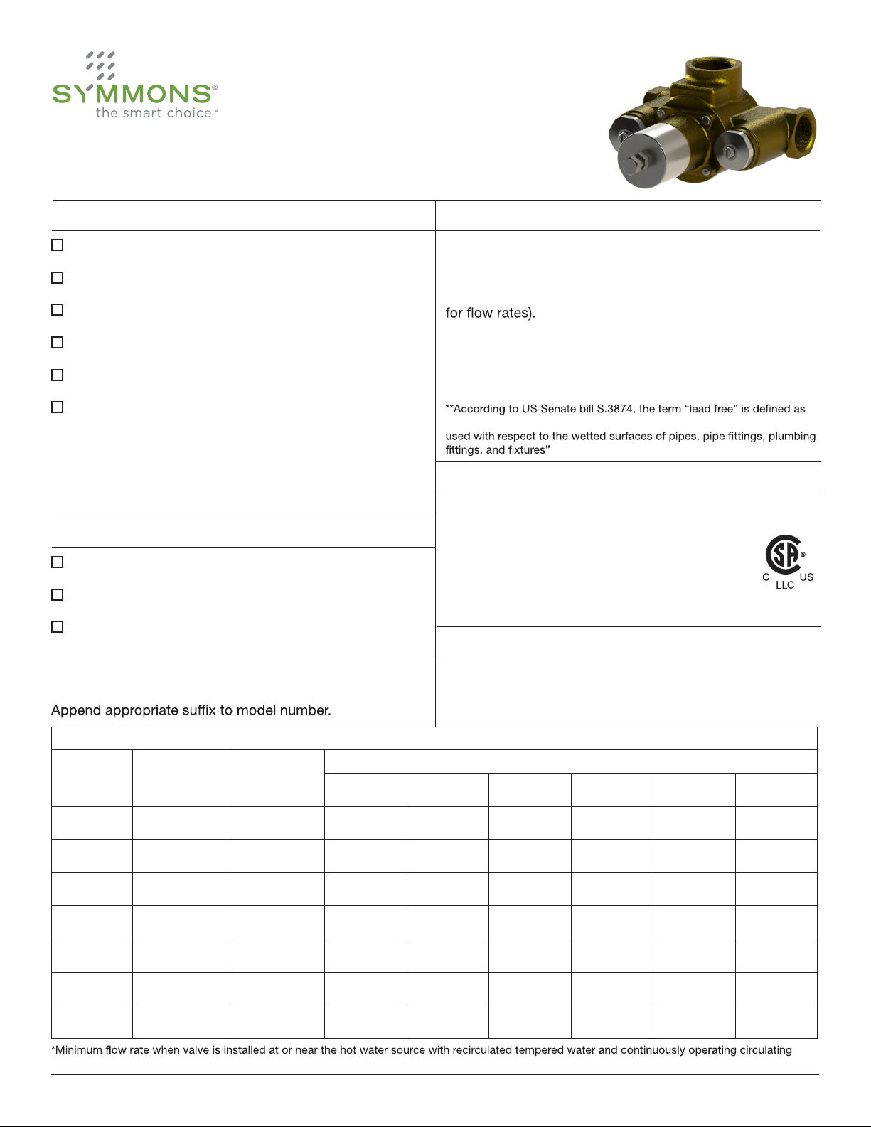
TempControl 7 Series
Operation & Maintenance Manual
Coordinating Model Numbers Specification
HTA-100
T-425-( )
BV-( )
SV-( )
TF-( )
WHA-1
High temp audio/visual alarm system
3” bimetal dial thermometer
Volume control shut off valves
Solenoid valve
Tee fittings
Water hammer arrestor
Note:
Insert proper model number in parenthesis.
Configurations (Components Certified Separately)
A
B
BW
Valve and piping assembly
Valve and piping in cabinet
Valve and piping in cabinet with cold
water bypass
TempControl thermostatic mixing valve made from lead
free** metal components. Models 102-700 feature
serviceable integral check stops. Models 900 & 1000
feature removable check stops with union ells (see table 1
Temperature control range:
70°F - 150°F (21.1°C - 65.6°C)
Approach temperature: 5°F (2.8°C)
follows: “not more than a weighted average of 0.25 percent lead when
Compliance
-ASME A112.18.1/CSA B125.1
-CSA B125.3
-ASSE 1017
-CA 116875 (AB 1953)
-NSF 372
-US S.3874
Warranty
Note:
Valve Model Min. Flow Rate* Min. Flow Rate
pump.
7-102
7-200
7-400
7-500
7-700
7-900
7-1000
0.5 gpm
(1.9 L/min)
0.5 gpm
(1.9 L/min)
0.5 gpm
(1.9 L/min)
0.5 gpm
(1.9 L/min)
0.5 gpm
(1.9 L/min)
0.5 gpm
(1.9 L/min)
0.5 gpm
(1.9 L/min)
0.5 gpm
(1.9 L/min)
5 gpm
(19 L/min)
9 gpm
(34 L/min)
13 gpm
(49 L/min)
13 gpm
(49 L/min)
13 gpm
(49 L/min)
13 gpm
(49 L/min)
5 Years - for commercial installations.
Refer to www.symmons.com/warranty for complete
warranty information.
Table 1: Flow Rate - gpm (L/min)
5 psi
(34 kPa)
1 gpm
(4 L/min)
7 gpm
(27 L/min)
18 gpm
(68 L/min)
22 gpm
(83 L/min)
25 gpm
(95 L/min)
30 gpm
(114 L/min)
38 gpm
(144 L/min)
10 psi
(69 kPa)
3 gpm
(11 L/min)
12 gpm
(46 L/min)
27 gpm
(102 L/min)
38 gpm
(144 L/min)
43 gpm
(163 L/min)
55 gpm
(209 L/min)
67 gpm
(254 L/min)
Pressure Differential - psi (kPa)
20 psi
(138 kPa)
6 gpm
(23 L/min)
18 gpm
(68 L/min)
37 gpm
(140 L/min)
50 gpm
(190 L/min)
57 gpm
(216 L/min)
76 gpm
(288 L/min)
100 gpm
(379 L/min)
25 psi
(172 kPa)
7 gpm
27 L/min)
21 gpm
(80 L/min)
41 gpm
(155 L/min)
55 gpm
(209 L/min)
62 gpm
(235 L/min)
84 gpm
(318 L/min)
111 gpm
(421 L/min)
30 psi
(207 kPa)
8 gpm
(30 L/min)
23 gpm
(87 L/min)
44 gpm
(167 L/min)
59 gpm
(224 L/min)
66 gpm
(250 L/min)
89 gpm
(337 L/min)
120 gpm
(455 L/min)
45 psi
(310 kPa)
11 gpm
(42 L/min)
27 gpm
(102 L/min)
53 gpm
(201 L/min)
70 gpm
(265 L/min)
77 gpm
(292 L/min)
104 gpm
(394 L/min)
140 gpm
(531 L/min)
1
Symmons Industries, Inc. ■ 31 Brooks Drive ■ Braintree, MA 02184 ■ (800)796-6667 ■ Fax: (800)961-9621
©2014 Symmons Industries, Inc.■ www.symmons.com ■ gethelp@symmons.com ■ ZV-3008 REV D 01/06/14
Page 2
A
H C
7-102, 7-200, 7-400, 7-500, 7-700, 7-900, 7-1000
TempControl 7 Series
Operation & Maintenance Manual
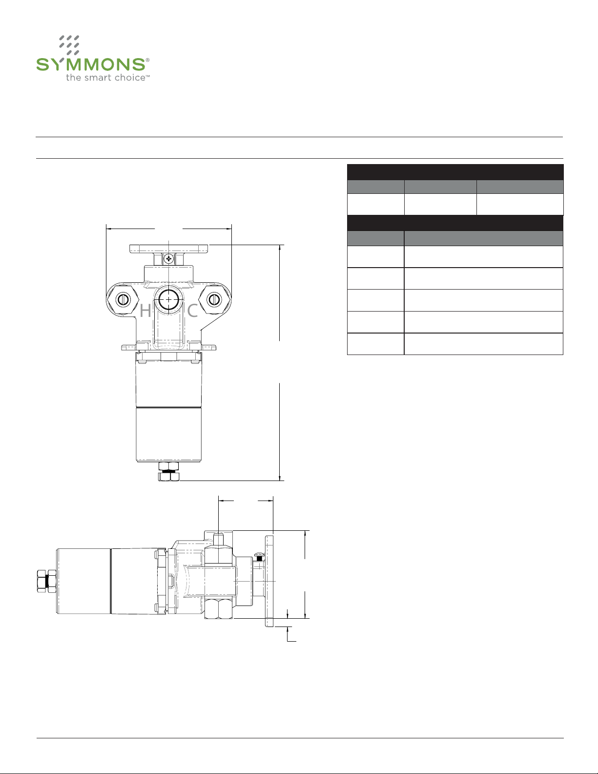
Dimensions (7-102)
Model No. Inlet Outlet
Dimension 7-102
TempControl Valve Sizes
7-102 1/2” 1/2”
Measurements
A 4 13/16”, 122 mm
B 9 1/4”, 235 mm
C 2 1/8”, 53 mm
D 3 3/8”, 86 mm
E 5/16”, 8 mm
B
C
D
Note:
1) Dimensions are subject to change without notice.
2
E
Symmons Industries, Inc. ■ 31 Brooks Drive ■ Braintree, MA 02184 ■ (800)796-6667 ■ Fax: (800)961-9621
©2014 Symmons Industries, Inc.■ www.symmons.com ■ gethelp@symmons.com ■ ZV-3008 REV D 01/06/14
Page 3
A
H C
7-102, 7-200, 7-400, 7-500, 7-700, 7-900, 7-1000
TempControl 7 Series
Operation & Maintenance Manual
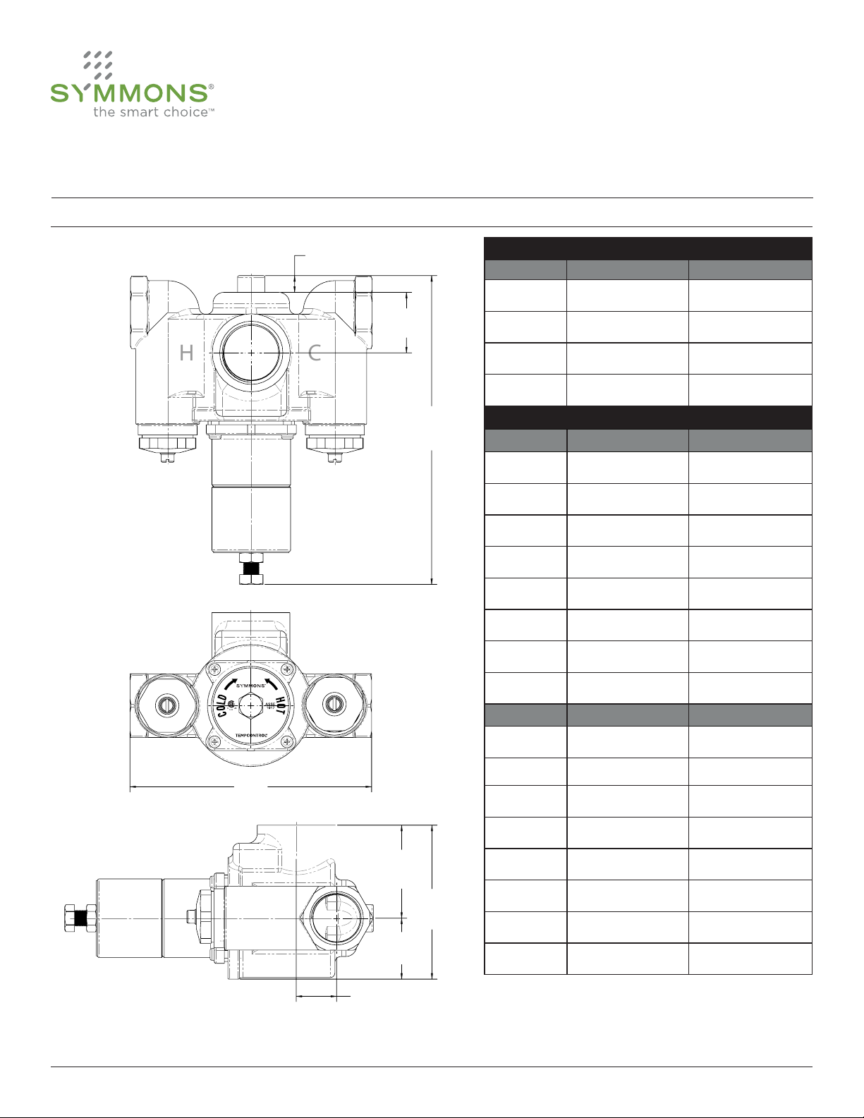
Dimensions (7-200, 7-400, 7-500, 7-700)
Model No. Inlet Outlet
7-200 3/4” 3/4”
TempControl Valve Sizes
B
C
7-400 3/4” 1”
7-500 1” 1 1/4”
7-700 1 1/4” 1 1/2”
Measurements
Dimension 7-200 7-400
A 1/2”, 13 mm 1/2”, 13 mm
B 1 7/8”, 46 mm 1 1/2”, 39 mm
C 8 15/16”, 226 mm 9 3/4”, 251 mm
D 5 15/16”, 150 mm 6 1/2”, 165 mm
E 2”, 51 mm 2 5/8”, 67 mm
F 3 5/16”, 84 mm 4 1/8”, 105 mm
G 1 5/16”, 33 mm 1 1/2”, 38 mm
H 11/16”, 17 mm 3/4”, 19 mm
Dimension 7-500 7-700
Note:
1) Dimensions are subject to change without notice.
3
A 1/2”, 13 mm 1/2”, 13 mm
B 1 15/16”, 49 mm 1 15/16 ”, 49 mm
D
E
C 9 5/8”, 248 mm 9 13/16”, 243 mm
D 7 11/16”, 195 mm 7 11/16”, 195 mm
E 2 15/16”, 75 mm 2 15/16”, 75 mm
F 4 7/8”, 124 mm 4 7/8”, 124 mm
F
G 1 15/16”, 49 mm 1 15/16”, 49 mm
G
H 1 5/16”, 33 mm 1 5/16”, 33 mm
H
Symmons Industries, Inc. ■ 31 Brooks Drive ■ Braintree, MA 02184 ■ (800)796-6667 ■ Fax: (800)961-9621
©2014 Symmons Industries, Inc.■ www.symmons.com ■ gethelp@symmons.com ■ ZV-3008 REV D 01/06/14
Page 4
H C
7-102, 7-200, 7-400, 7-500, 7-700, 7-900, 7-1000
TempControl 7 Series
Operation & Maintenance Manual
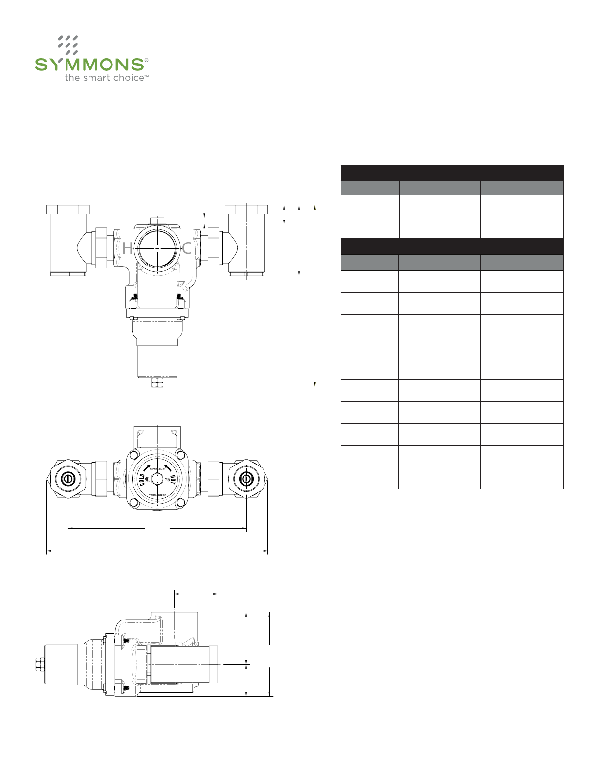
Dimensions (7-900, 7-1000)
Model No. Inlet Outlet
A B
C
Dimension 7-900 7-1000
D
TempControl Valve Sizes
7-900 1 1/2” 1 1/2”
7-1000 1 1/2” 2”
Measurements
A 7/16”, 11 mm 7/16”, 11 mm
B 1 3/16”, 31 mm 1 3/16”, 31 mm
C 4 9/16”, 116 mm 4 9/16”, 116 mm
D 11 1/6”, 280 mm 11 3/8”, 289 mm
E 11 1/2”, 296 mm 11 1/2”, 296 mm
E
F
F 14 1/4”, 365 mm 14 1/4”, 365 mm
G 2 13/16”, 71 mm 2 13/16”, 71 mm
H 3 3/8”, 86 mm 3 3/8”, 86 mm
I 5 7/16”, 138 mm 5 7/16”, 138 mm
J 2 1/16”, 52 mm 2 1/16”, 52 mm
G
H
I
Note:
1) Dimensions are subject to change without notice.
4
J
Symmons Industries, Inc. ■ 31 Brooks Drive ■ Braintree, MA 02184 ■ (800)796-6667 ■ Fax: (800)961-9621
©2014 Symmons Industries, Inc.■ www.symmons.com ■ gethelp@symmons.com ■ ZV-3008 REV D 01/06/14
Page 5
7-102, 7-200, 7-400, 7-500, 7-700, 7-900, 7-1000
TempControl 7 Series
Operation & Maintenance Manual
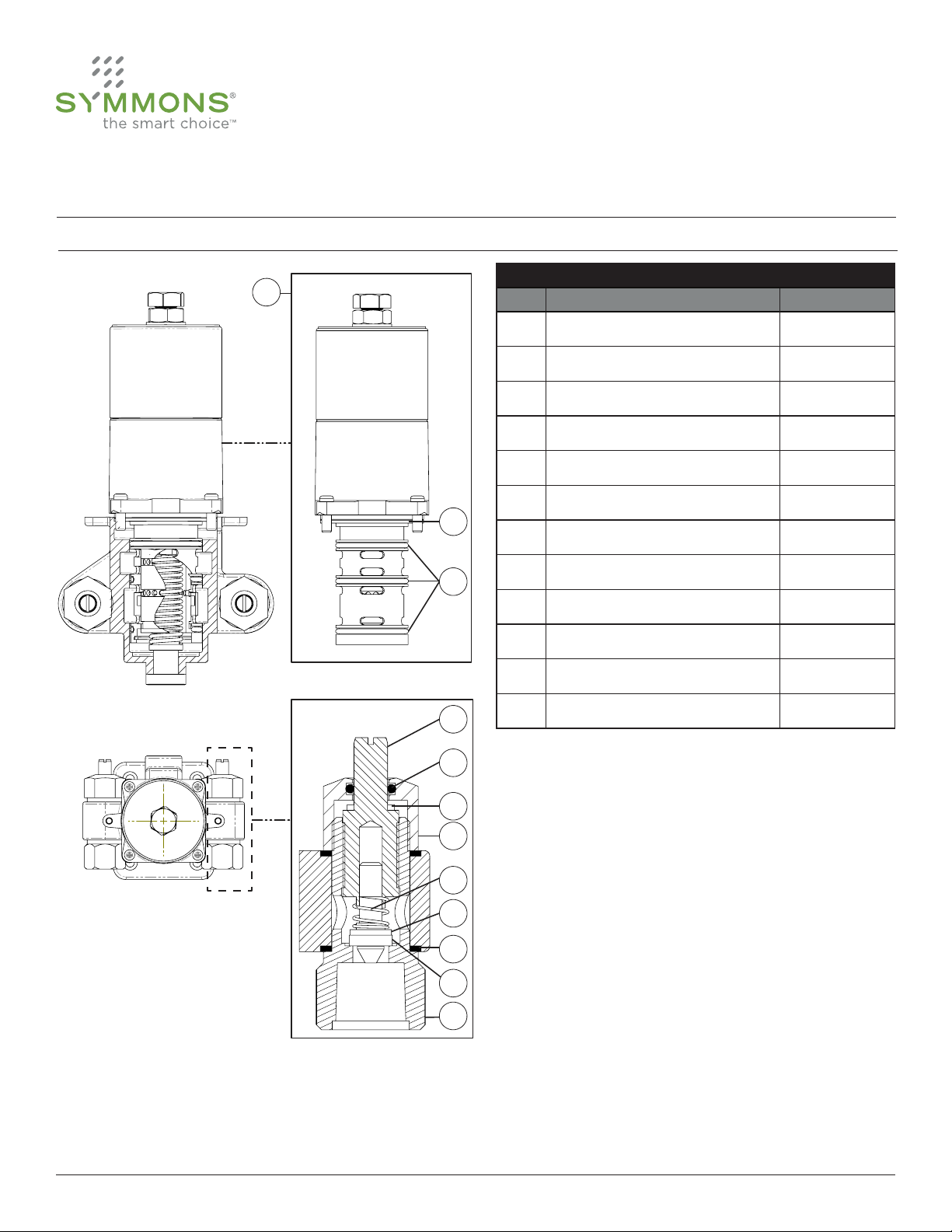
Parts Breakdown (7-102)
A
Item Description Part No.
A Valve replacement cartridge 7-102NW
B Check stop spindle CSE-35
C O-ring CE-29
D Washer CSE-31
E Check stop cap CSE-26
F Check spring CSE-34
K
G Check assembly CSE-33
Replacement Parts for Model 102
L
B
C
D
E
F
G
H
J
H Gasket (x2) CE-30
I Check stop washer CSE-32
J Check stop body with stop seat CSE-25
K Casing Gasket TT-11-100
L Sleeve o-rings (x3) TT-15-100
I
5
Symmons Industries, Inc. ■ 31 Brooks Drive ■ Braintree, MA 02184 ■ (800)796-6667 ■ Fax: (800)961-9621
©2014 Symmons Industries, Inc.■ www.symmons.com ■ gethelp@symmons.com ■ ZV-3008 REV D 01/06/14
Page 6
7-102, 7-200, 7-400, 7-500, 7-700, 7-900, 7-1000
TempControl 7 Series
Operation & Maintenance Manual
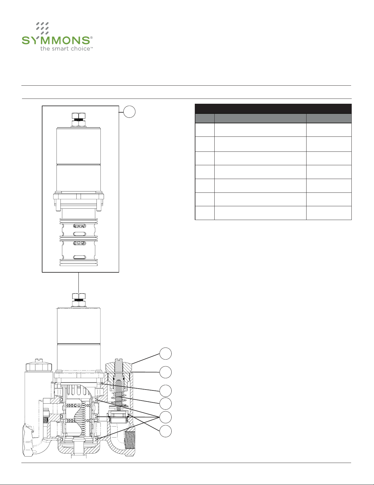
Parts Breakdown (7-200, 7-400, 7-500, 7-700)
A
Replacement Parts for Models 200-700
Item Description Part No.
A Valve replacement cartridge 7-( )NW
B
C Cap gasket TT-21-( )
D Casing gasket TT-11-( )
E Check spindle and spring TT-181-( )
F Sleeve o-rings (x3) TT-15-( )
G Check seat TT-26-( )
Notes:
1) Insert proper model number in parenthesis.
2) Item B contains cap gasket, check spring, bonnet
assembly and check assembly.
Complete replacement stop
assembly
TT-50AN-( )
B
C
D
E
F
G
6
Symmons Industries, Inc. ■ 31 Brooks Drive ■ Braintree, MA 02184 ■ (800)796-6667 ■ Fax: (800)961-9621
©2014 Symmons Industries, Inc.■ www.symmons.com ■ gethelp@symmons.com ■ ZV-3008 REV D 01/06/14
Page 7
7-102, 7-200, 7-400, 7-500, 7-700, 7-900, 7-1000
TempControl 7 Series
Operation & Maintenance Manual
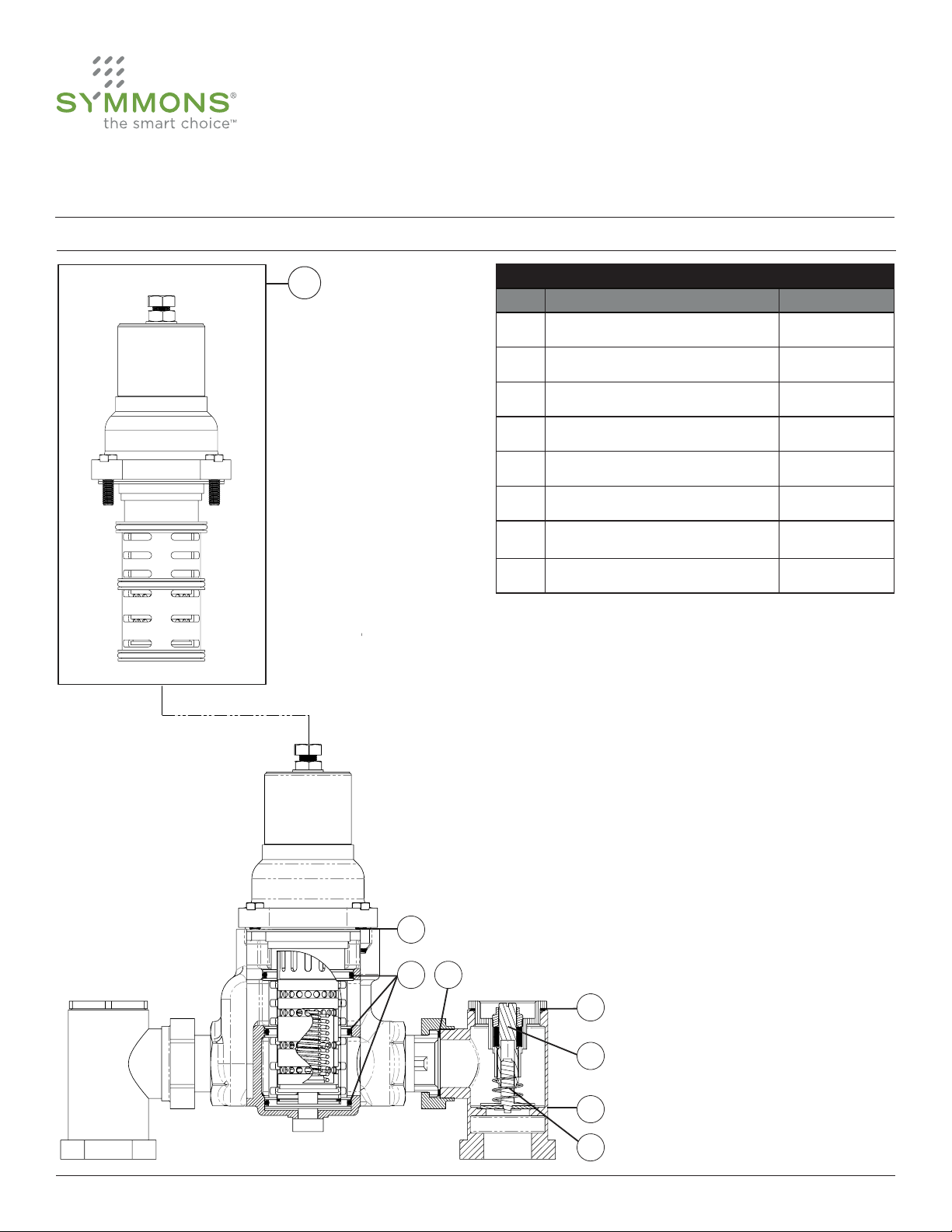
Parts Breakdown (7-900, 7-1000)
A
Replacement Parts for Model 900 & 1000
Item Description Part No.
A Valve replacement cartridge 7-( )NW
B Casing gasket TT-11-( )
C Sleeve o-rings (x3) TT-15-( )
D Gasket between stops TT-32A
E Cap gasket TT-21-( )
F Stop spindle TT-22-( )
G
H Check spindle and spring TT-200-( )
Notes:
1) Insert proper model number in parenthesis.
2) Item G contains check body, cap, check spring
and check assembly.
Complete replacement stop
body assembly
TT-27-( )
B
C
D
E
F
G
H
7
Symmons Industries, Inc. ■ 31 Brooks Drive ■ Braintree, MA 02184 ■ (800)796-6667 ■ Fax: (800)961-9621
©2014 Symmons Industries, Inc.■ www.symmons.com ■ gethelp@symmons.com ■ ZV-3008 REV D 01/06/14
Page 8
7-102, 7-200, 7-400, 7-500, 7-700, 7-900, 7-1000
TempControl 7 Series
Operation & Maintenance Manual
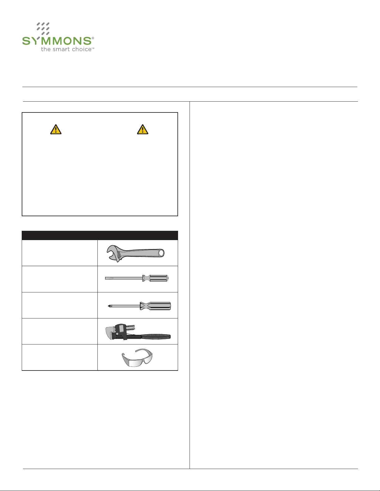
Installation
Technical Assistance and Sizing
CAUTION
When these installation, operation and service
instructions are not followed, TempControl functionality
and service life will be greatly impaired.
All TempControl installations must have a
thermometer and shut off valve in the tempered water
outlet (as shown in diagrams) for proper trouble
shooting service.
Tools Required for Installation
Adjustable wrench
Flat head screwdriver
Phillips head screwdriver
Pipe wrench
For assistance and technical support in sizing and
selection of the proper TempControl valve or system,
consult the Symmons TempSize™ computer sizing software, your local representative or Symmons
Customer Service Department at 1-800-SYMMONS.
TempControl Location
An underlying premise of thermostatic water controller
installations is an acknowledgement that thermostatic
mixing valves will not operate properly when the hot and
cold supplies serving such valves are subjected to pressure disturbances when owing less than full capacity. In
a correctly designed mechanical room, the supply pressures are stable and not subject to pressure disturbances. As a result, when a TempControl valve is indicated as
being located in the mechanical room, a Hi-Low system
will not be recommended.
When the valve’s location is indicated as being outside
of the mechanical room, it is assumed that there is a
potential for pressure uctuations in the hot and cold
supply lines servicing a TempControl valve and a HiLow system will automatically be recommended.
Note: If the system is designed so that the TempControl
valve is not subjected to high-low ow demand, even
though it is located outside the mechanical room, a
single TempControl valve will operate properly.
Safety goggles
8
Symmons Industries, Inc. ■ 31 Brooks Drive ■ Braintree, MA 02184 ■ (800)796-6667 ■ Fax: (800)961-9621
©2014 Symmons Industries, Inc.■ www.symmons.com ■ gethelp@symmons.com ■ ZV-3008 REV D 01/06/14
Installation Tips
All piping should be thoroughly ushed before TempControl is installed. The TempControl can be installed in any
position as long as Hot Water is connected to “H” port
and Cold Water is connected to “C” port. Close service
stops on TempControl, remove cartridge, (see page 11
for Cartridge Removal & Replacement section), turn on
water supply and open stops wide to thoroughly ush
piping before putting valve in service. TempControl is set
at factory to deliver approximately 100° F.
Page 9
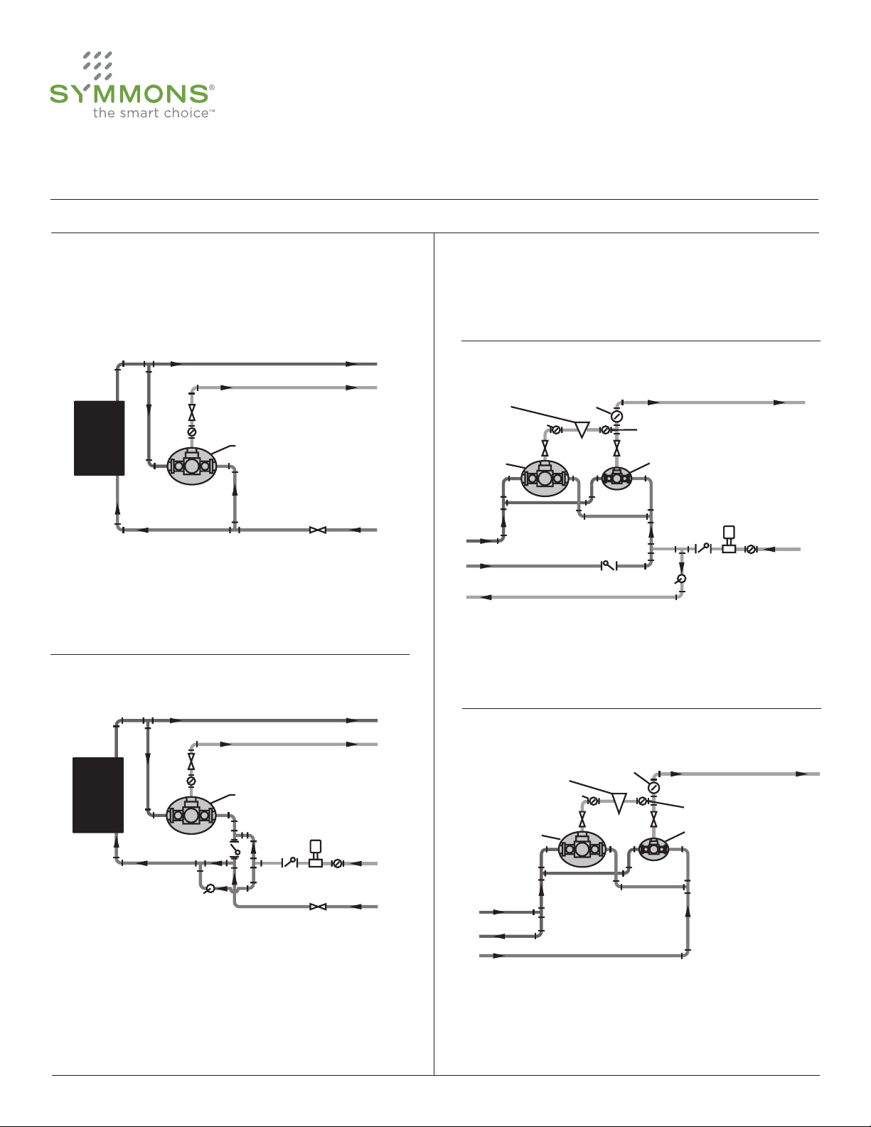
Diagram 1
Single Valve Installation at or near Hot Water Source
tempered water main hot supply to system
high temperature hot (if required for laundry, etc.)
cold supply
valve
valve
thermometer
TempControl thermostatic
water controller
hot
water
tank,
heater,
etc.
valve
Diagram 2
Single Valve Installation with Recirculating
Tempered Water at Hot Water Source
tempered water main hot supply to system
high temperature hot (if required for laundry, etc.)
tempered water return
valve
thermometer
TempControl thermostatic
water controller
hot
water
tank,
heater,
etc.
check
thermometer
circulating pump
ball valve
cold supply
check
Diagram 3
Remote HI-LOW System Installation with
Recirculating Tempered Water
tempered water to showers, lavatories, etc.
V1 valve
TMV1
V2 valve
TMV2
check
thermometer
circulating pump
ball valve
hot supply
cold supply
tempered water return to cold inlet of heater
thermometer
check
PRV valve
P1 pressure gauge
P2 pressure gauge
7-102, 7-200, 7-400, 7-500, 7-700, 7-900, 7-1000
TempControl 7 Series
Operation & Maintenance Manual
Installation
Piping Diagrams
Diagram 1 INSTALLATION AT OR NEAR THE HOT
WATER SOURCE: TempControl must be positioned
below the hot water tank or heater, well below the high
temperature water line. This procedure creates a heat
trap and protects against hot water migrating through
the controller.
plumbing system, no water can be added to the system;
therefore, the “cold” and “hot” supplies to the TempControl must come from within the system as described
below using the ball valve for ne tuning the operation
as outlined in (a) and (b).
Diagram 3 REMOTE HI-LOW INSTALLATION WITH
RECIRCULATING TEMPERED WATER OR HOT WATER
RETURN: TempControl Hi-Low system must have the
return line connected exactly as shown (See Diagram 2
notes).
Diagram 2 INSTALLATION WITH RECIRCULATING
TEMPERED WATER AT HOT WATER SOURCE: TempControl must have the return line connected exactly as
shown. This procedure allows the controller to maintain
the set temperature during periods of no draw by (a)
allowing the major volume of return water to supply the
cold inlet of the TempControl and (b) the minor volume
of return water to be reheated and supply the hot inlet of
the TempControl. When there is no water draw on the
9
Symmons Industries, Inc. ■ 31 Brooks Drive ■ Braintree, MA 02184 ■ (800)796-6667 ■ Fax: (800)961-9621
©2014 Symmons Industries, Inc.■ www.symmons.com ■ gethelp@symmons.com ■ ZV-3008 REV D 01/06/14
Remote HI-LOW System Installation with
Recirculating Hot Water
PRV valve
P1 pressure gauge
TMV1
hot supply
hot water return
cold supply
thermometer
V1 valve V2 valve
tempered water to showers,
lavatories, etc.
P2 pressure gauge
TMV2
Diagram 4 REMOTE HI-LOW INSTALLATION WITH
RECIRCULATING HOT WATER SUPPLY ONLY:
TempControl Hi-Low system must be piped as shown.
Diagram 4
Page 10

7-102, 7-200, 7-400, 7-500, 7-700, 7-900, 7-1000
TempControl 7 Series
Operation & Maintenance Manual
Operation & Maintenance
Operation & Adjustment
Cycle valve to full hot (counterclockwise) then cold
(clockwise) 3 full times allowing valve to reach full
temperature. With approximately 80% of the design
intent owing water, turn adjustment bolt to obtain
desired setting and lock nut in place. Thermostatic
water controllers should be sized according to the ow
capacity required from the valve, NOT the pipe size supplied to the valve. For assistance and technical support
in sizing and selection of the proper TEMPCONTROL
Thermostatic Water Controller, consult the Symmons
TEMPSIZE™ computer sizing software, your local representative or Symmons Customer Service Department at
1-800-SYMMONS.
CAUTION: Turning adjustment bolt fully counterclockwise will remove bolt from TempControl. If
this occurs simply replace bolt.
For systems piped to Diagram 2:
1. With ball valve closed, set TempControl to desired
temperature with water owing from tempered water
line.
2. After obtaining desired temperature, stop the water
ow.
3. Crack the ball valve open so that a small amount of
water is returned to the hot water source. This allows
the TempControl to maintain the set temperature
during periods of no draw on the system.
4. During no draw, observe the thermometer on the
discharge of the TempControl. If the temperature
increases above the setting in Step 1, close the ball
valve slightly or if temperature decreases, open it
slightly.
For systems piped to Diagram 3:
1. Turn off recirculating pump and close ball valve.
2. Shut off (V1).
3. Open 5 showers or equivalent to the full hot position.
4. Set small TempControl valve (TMV2) to the full cold
position and note the temperature on thermometer.
5. Shut off valve (V2) and open valve (V1). Set large
TempControl valve (TMV1) to desired system
temperature (make sure adjustment screw on PRV
valve is in the full clockwise position).
6. Shut off 2 showers or equivalent (leaving 3 still on) and open
valve (V2).
7. Turn PRV adjustment screw counter-clockwise until
temperature (T) equals that obtained in step #4.
8. Adjust TempControl valve (TMV2) to desired system
temperature and system will be in operational mode.
9. Stop the water ow, after obtaining desired temperature and turn on the recirculating pump.
Crack the ball valve open so that a small amount of
10.
water is returned to the hot water source. This allows
the TempControl to maintain the set temperature
during periods of no draw on the system.
11.
During no draw, observe the thermometer on the
discharge on the TempControl. If the temperature
increases above the setting in step #8, close the ball
valve slightly or open it if the temperature decreases.
For systems piped to Diagram 4:
Follow steps 2 through 9 for systems piped to
Diagram 3. Ignore reference to recirculating pump in
step 9 (not applicable to this installation).
Maintenance
The cartridge unit contains the entire valve control
mechanism. For non-interrupted service, keep a spare
cartridge on hand.
TempControl valve control mechanism must be kept
clean and free from deposits and any foreign matter
build-up that will be present in many water systems.
Inspect within 30 days of initial installation or operation. If inspection determines that your water system
causes deposits and foreign matter build-up monthly, then valve should be cleaned monthly as follows:
Remove cartridge (see page 11 for Cartridge Removal
& Replacement section) and soak in any acceptable
de-liming agent (or regular household vinegar). Wash off
deposits, be sure piston is moving freely in its sleeve,
and replace cartridge. Clean more frequently if your
system so demands (do not completely remove piston
from cartridge).
The Check Valves in the TempControl are highly important
10
Symmons Industries, Inc. ■ 31 Brooks Drive ■ Braintree, MA 02184 ■ (800)796-6667 ■ Fax: (800)961-9621
©2014 Symmons Industries, Inc.■ www.symmons.com ■ gethelp@symmons.com ■ ZV-3008 REV D 01/06/14
Page 11

7-102, 7-200, 7-400, 7-500, 7-700, 7-900, 7-1000
TempControl 7 Series
Operation & Maintenance Manual
Operation & Maintenance
factors in its proper operation. If chips, dirt or other foreign
materials lodge on the seats and prevent the checks from
fully seating, there may be a bypass of water into the
opposing line, and the TempControl will not operate to its
set delivery temperature. A bypass may be detected by
feeling the supply line while the TempControl is not operating. If, for example, the cold line feels hot, the cold water
check is not seating properly. It should be removed and
the check and its seat cleaned.
Cartridge Removal & Replacement
Before removing a used cartridge for cleaning, have
new casing gasket and sleeve o-rings on hand.
Shut off supplies at stop checks by turning clockwise.
Remove 4 bolts on cartridge bolt ange.
With 2 large bladed screwdrivers, pry evenly on two
opposite sides of bolt ange until cartridge is free to be
removed by hand. Pull out cartridge with a twisting and
turning action, always keeping cartridge on center line.
Leave compensating spring in position at bottom center
of valve body.
Clean cartridge as described in maintenance instructions.
Replace sleeve O-rings and grease same.
With a twisting and pushing action, replace cartridge
in valve body until bolt ange is rmly against housing
gasket.
While holding cartridge in place, replace bolts and tighten. Do not attempt to pull cartridge into position with
bolts—it will damage the valve control mechanism.
Open stops and adjust temperature.
Seasonal Use
When a TempControl is used seasonally (schools, campgrounds, golf clubs, etc.) the cartridge must be removed
and thoroughly drained of all water to prevent freeze
damage. The check stops should also be removed to
drain all water from the supply lines and valve body (see
“Cartridge Removal & Replacement”). This will prohibit
damage caused by freezing water.
11
Symmons Industries, Inc. ■ 31 Brooks Drive ■ Braintree, MA 02184 ■ (800)796-6667 ■ Fax: (800)961-9621
©2014 Symmons Industries, Inc.■ www.symmons.com ■ gethelp@symmons.com ■ ZV-3008 REV D 01/06/14
Page 12

7-102, 7-200, 7-400, 7-500, 7-700, 7-900, 7-1000
TempControl 7 Series
Operation & Maintenance Manual
Trouble Shooting Chart
For Tempered Water Recirculated Systems
Problem Cause Solution
Thermometer in TempControl outlet
rises to temperature of the heater at
start of no draw (i.e. sink or
showers not running, etc.).
Hot water temperature at sink or
shower is below set point of
TempControl.
Temperature rises.
Cannot elevate or decrease
tempered water by turning
adjustment bolt.
Temperature drops during draw (sink,
shower running, etc.).
No circulation of tempered water
because return line is piped to the hot
water source only.
Sufcient circulation of tempered
water is not reaching the hot water
source.
Not piped to Diagrams 2 or 3. Ball
valve too far open.
Piston stuck with foreign matter.
Valve was set in no draw mode.
Repipe system to diagram 2 or 3
(pg. 9) which allows the discharge of
the pump (tempered water return) to
go back to the hot water source and
the cold inlet of the TempControl.
Repipe system to diagram 2 or 3
(pg. 9) which allows the discharge of
the pump (tempered water return) to
go back to the hot water source and
the cold inlet of the TempControl.
Check valve must be installed on cold
supply to controller or adjust ball valve
(see diagram 2 or 3 on page 9).
Remove cartridge and soak in
household vinegar for an hour. If
piston does not free after soaking
replace cartridge.
Run showers and sinks and then set
valve.
For Tempered Water Non-Recirculated Systems
Problem Cause Solution
Bypass, cold to hot or hot to cold. Checks not properly seating.
12
Symmons Industries, Inc. ■ 31 Brooks Drive ■ Braintree, MA 02184 ■ (800)796-6667 ■ Fax: (800)961-9621
©2014 Symmons Industries, Inc.■ www.symmons.com ■ gethelp@symmons.com ■ ZV-3008 REV D 01/06/14
Clean fouled checks, or if damged,
replace damaged parts.
Page 13

7-102, 7-200, 7-400, 7-500, 7-700, 7-900, 7-1000
TempControl Serie 7
Manual de funcionamiento y mantenimiento
Coordinación de números de modelo Especificación
HTA-100
Sistema de alarma sonora/visual de
alta temperatura
T-425-( )
BV-( )
SV-( )
TF-( )
WHA-1
Termómetro de aguja bimetálico de 3"
Válvulas de cierre para control de volumen
Válvula de solenoide
Accesorios en T
Silenciador de martillo hidráulico
Nota:
Introduzca el número de modelo adecuado entre paréntesis.
Configuraciones (Componentes certificados
por separado)
A
B
BW
Conjunto de válvula y tuberías
Válvula y tuberías en gabinete
Válvula y tuberías en gabinete
con derivación de agua fría
Válvula mezcladora termostática TempControl fabricada con
componentes metálicos libres de plomo**. Los modelos 102700 ofrecen válvulas antirretorno integrales con capacidad
de mantenimiento. Los modelos 900 y 1000 cuentan con
válvulas antirretorno extraíble con celdas de unión
Rango de control de temperatura:
70 °F - 150 °F (21,1 °C - 65,6 °C)
Temperatura de enfoque: 5 °F (2,8 °C)
que un promedio ponderado de 0,25 por ciento de plomo cuando se
de tubería, accesorios de fontanería y artefactos”
Cumplimiento
-ASME A112.18.1/CSA B125.1
-CSA B125.3
-ASSE 1017
-CA 116875 (AB 1953)
-NSF 372
-US S.3874
Garantía
Nota:
Modelo de
válvula
7-102
7-200
7-400
7-500
7-700
7-900
7-1000
circulación de funcionamiento continuo.
13
0.5 gpm
(1,9 L/min)
0.5 gpm
(1,9 L/min)
0.5 gpm
(1,9 L/min)
0.5 gpm
(1,9 L/min)
0.5 gpm
(1,9 L/min)
0.5 gpm
(1,9 L/min)
0.5 gpm
(1,9 L/min)
Symmons Industries, Inc. ■ 31 Brooks Drive ■ Braintree, MA 02184 ■ (800)796-6667 ■ Fax: (800)961-9621
©2014 Symmons Industries, Inc.■ www.symmons.com ■ gethelp@symmons.com ■ ZV-3008 REV D 01/06/14
0.5 gpm
(1,9 L/min)
5 gpm
(19 L/min)
9 gpm
(34 L/min)
13 gpm
(49 L/min)
13 gpm
(49 L/min)
13 gpm
(49 L/min)
13 gpm
(49 L/min)
5 psi
(34 kPa)
1 gpm
(4 L/min)
7 gpm
(27 L/min)
18 gpm
(68 L/min)
22 gpm
(83 L/min)
25 gpm
(95 L/min)
30 gpm
(114 L/min)
38 gpm
(144 L/min)
5 años - para instalaciones comerciales.
Consulte www.symmons.com/warranty para obtener
información completa sobre la garantía.
Diferencial de presión - psi (kPa)
10 psi
(69 kPa)
3 gpm
(11 L/min)
12 gpm
(46 L/min)
27 gpm
(102 L/min)
38 gpm
(144 L/min)
43 gpm
(163 L/min)
55 gpm
(209 L/min)
67 gpm
(254 L/min)
20 psi
(138 kPa)
6 gpm
(23 L/min)
18 gpm
(68 L/min)
37 gpm
(140 L/min)
50 gpm
(190 L/min)
57 gpm
(216 L/min)
76 gpm
(288 L/min)
100 gpm
(379 L/min)
25 psi
(172 kPa)
7 gpm
27 L/min)
21 gpm
(80 L/min)
41 gpm
(155 L/min)
55 gpm
(209 L/min)
62 gpm
(235 L/min)
84 gpm
(318 L/min)
111 gpm
(421 L/min)
30 psi
(207 kPa)
8 gpm
(30 L/min)
23 gpm
(87 L/min)
44 gpm
(167 L/min)
59 gpm
(224 L/min)
66 gpm
(250 L/min)
89 gpm
(337 L/min)
120 gpm
(455 L/min)
45 psi
(310 kPa)
11 gpm
(42 L/min)
27 gpm
(102 L/min)
53 gpm
(201 L/min)
70 gpm
(265 L/min)
77 gpm
(292 L/min)
104 gpm
(394 L/min)
140 gpm
(531 L/min)
Page 14

A
H C
7-102, 7-200, 7-400, 7-500, 7-700, 7-900, 7-1000
TempControl Serie 7
Manual de funcionamiento y mantenimiento
Dimensiones (7-102)
Dimensión 7-102
B
Tamaños de la válvula TempControl
N.° de
modelo
7-102 1/2” 1/2”
A 4 13/16”, 122 mm
B 9 1/4”, 235 mm
C 2 1/8”, 53 mm
D 3 3/8”, 86 mm
E 5/16”, 8 mm
Entrada Salida
Medidas
Nota:
1) Las dimensiones pueden cambiar sin previo aviso.
14
C
D
E
Symmons Industries, Inc. ■ 31 Brooks Drive ■ Braintree, MA 02184 ■ (800)796-6667 ■ Fax: (800)961-9621
©2014 Symmons Industries, Inc.■ www.symmons.com ■ gethelp@symmons.com ■ ZV-3008 REV D 01/06/14
Page 15

A
H C
7-102, 7-200, 7-400, 7-500, 7-700, 7-900, 7-1000
TempControl Serie 7
Manual de funcionamiento y mantenimiento
Dimensiones (7-200, 7-400, 7-500, 7-700)
N.° de
modelo
7-200 3/4” 3/4”
B
7-400 3/4” 1”
7-500 1” 1 1/4”
7-700 1 1/4” 1 1/2”
Tamaños de la válvula TempControl
Entrada Salida
D
C
Medidas
Dimensión 7-200 7-400
A 1/2”, 13 mm 1/2”, 13 mm
B 1 7/8”, 46 mm 1 1/2”, 39 mm
C 8 15/16”, 226 mm 9 3/4”, 251 mm
D 5 15/16”, 150 mm 6 1/2”, 165 mm
E 2”, 51 mm 2 5/8”, 67 mm
F 3 5/16”, 84 mm 4 1/8”, 105 mm
G 1 5/16”, 33 mm 1 1/2”, 38 mm
H 11/16”, 17 mm 3/4”, 19 mm
Dimensión 7-500 7-700
A 1/2”, 13 mm 1/2”, 13 mm
B 1 15/16”, 49 mm 1 15/16”, 49 mm
C 9 5/8”, 248 mm 9 13/16”, 243 mm
Nota:
1) Las dimensiones pueden cambiar sin previo aviso.
15
D 7 11/16”, 195 mm 7 11/16”, 195 mm
E
F
G
E 2 15/16”, 75 mm 2 15/16”, 75 mm
F 4 7/8”, 124 mm 4 7/8”, 124 mm
G 1 15/16”, 49 mm 1 15/16”, 49 mm
H 1 5/16”, 33 mm 1 5/16”, 33 mm
H
Symmons Industries, Inc. ■ 31 Brooks Drive ■ Braintree, MA 02184 ■ (800)796-6667 ■ Fax: (800)961-9621
©2014 Symmons Industries, Inc.■ www.symmons.com ■ gethelp@symmons.com ■ ZV-3008 REV D 01/06/14
Page 16

H C
7-102, 7-200, 7-400, 7-500, 7-700, 7-900, 7-1000
TempControl Serie 7
Manual de funcionamiento y mantenimiento
Dimensiones (7-900, 7-1000)
A B
Tamaños de la válvula TempControl
N.° de
modelo
7-900 1 1/2” 1 1/2”
Entrada Salida
C
D
7-1000 1 1/2” 2”
Medidas
Dimensión 7-900 7-1000
A 7/16”, 11 mm 7/16”, 11 mm
B 1 3/16”, 31 mm 1 3/16”, 31 mm
C 4 9/16”, 116 mm 4 9/16”, 116 mm
D 11 1/6”, 280 mm 11 3/8”, 289 mm
E 11 1/2”, 296 mm 11 1/2”, 296 mm
F 14 1/4”, 365 mm 14 1/4”, 365 mm
G 2 13/16”, 71 mm 2 13/16”, 71 mm
H 3 3/8”, 86 mm 3 3/8”, 86 mm
I 5 7/16”, 138 mm 5 7/16”, 138 mm
J 2 1/16”, 52 mm 2 1/16”, 52 mm
Nota:
1) Las dimensiones pueden cambiar sin previo aviso.
16
E
F
G
H
I
J
Symmons Industries, Inc. ■ 31 Brooks Drive ■ Braintree, MA 02184 ■ (800)796-6667 ■ Fax: (800)961-9621
©2014 Symmons Industries, Inc.■ www.symmons.com ■ gethelp@symmons.com ■ ZV-3008 REV D 01/06/14
Page 17

7-102, 7-200, 7-400, 7-500, 7-700, 7-900, 7-1000
TempControl Serie 7
Manual de funcionamiento y mantenimiento
Desglose de partes (7-102)
A
Artículo Descripción N.° de parte
A
B Eje de la válvula antirretorno CSE-35
C Anillo de goma CE-29
D Arandela CSE-31
Repuestos para el modelo 102
Reemplazo del cartucho
de la válvula
7-102NW
K
L
B
C
D
E
E
F Resorte antirretorno CSE-34
G Ensamblaje antirretorno CSE-33
H Junta de estanqueidad (x2) CE-30
I
J
K
L
Tapa de la válvula
antirretorno
Arandela de la válvula
antirretorno
Cuerpo de la válvula
antirretorno con asiento
de retención
Junta de estanqueidad
de la carcasa
Anillos de goma de
manguito (x3)
CSE-26
CSE-32
CSE-25
TT-11-100
TT-15-100
F
17
G
H
I
J
Symmons Industries, Inc. ■ 31 Brooks Drive ■ Braintree, MA 02184 ■ (800)796-6667 ■ Fax: (800)961-9621
©2014 Symmons Industries, Inc.■ www.symmons.com ■ gethelp@symmons.com ■ ZV-3008 REV D 01/06/14
Page 18

7-102, 7-200, 7-400, 7-500, 7-700, 7-900, 7-1000
TempControl Serie 7
Manual de funcionamiento y mantenimiento
Desglose de partes (7-200, 7-400, 7-500, 7-700)
A
Repuestos para modelos 200-700
Artículo Descripción N.° de parte
A
B
C
D
E Eje y resorte antirretorno TT-181-( )
F
G Asiento antirretorno TT-26-( )
Notas:
1) Introduzca el número de modelo adecuado
entre paréntesis.
2) El Artículo B contiene la junta de estanqueidad de la
tapa, el resorte antirretorno, ensamblaje de bonete
y ensamblaje antirretorno.
Reemplazo del cartucho
de la válvula
Repuesto del ensamblaje
de retención completo
Junta de estanqueidad
de la tapa
Junta de estanqueidad
de la carcasa
Anillos de goma de
manguito (x3)
7-( )NW
TT-50AN-( )
TT-21-( )
TT-11-( )
TT-15-( )
18
B
C
D
E
F
G
Symmons Industries, Inc. ■ 31 Brooks Drive ■ Braintree, MA 02184 ■ (800)796-6667 ■ Fax: (800)961-9621
©2014 Symmons Industries, Inc.■ www.symmons.com ■ gethelp@symmons.com ■ ZV-3008 REV D 01/06/14
Page 19

7-102, 7-200, 7-400, 7-500, 7-700, 7-900, 7-1000
TempControl Serie 7
Manual de funcionamiento y mantenimiento
Desglose de partes (7-900, 7-1000)
A
Repuestos para los modelos 900 y 1000
Artículo Descripción N.° de parte
A
B
C
D
E
F Eje de retención TT-22-( )
G
H Eje y resorte antirretorno TT-200-( )
Notas:
1) I ntroduzca el número de modelo adecuado
entre paréntesis.
2) El Artículo G contiene cuerpo antirretorno, tapa, resorte
antirretorno y ensamblaje antirretorno.
Reemplazo del cartucho
de la válvula
Junta de estanqueidad
de la carcasa
Anillos de goma de
manguito (x3)
Junta de estanqueidad
entre retenciones
Junta de estanqueidad
de la tapa
Repuesto del ensamblaje
de cuerpo de retención
completo
7-( )NW
TT-11-( )
TT-15-( )
TT-32A
TT-21-( )
TT-27-( )
19
B
C
D
E
F
G
H
Symmons Industries, Inc. ■ 31 Brooks Drive ■ Braintree, MA 02184 ■ (800)796-6667 ■ Fax: (800)961-9621
©2014 Symmons Industries, Inc.■ www.symmons.com ■ gethelp@symmons.com ■ ZV-3008 REV D 01/06/14
Page 20

7-102, 7-200, 7-400, 7-500, 7-700, 7-900, 7-1000
TempControl Serie 7
Manual de funcionamiento y mantenimiento
Instalación
Asistencia técnica y dimensionamiento
PRECAUCIÓN
Si no se siguen estas instrucciones de instalación,
operación y servicio, la funcionalidad y la vida útil de
TempControl se deteriorarán considerablemente.
Todas las instalaciones de TempControl deben tener
un termómetro y válvula de cierre en la salida de agua
templada (como se muestra en los diagramas) para el
servicio adecuado de resolución de problemas.
Herramientas necesarias para la instalación
Llave regulable
Destornillador plano
Destornillador Phillips
Para obtener ayuda y soporte técnico en el
dimensionamiento y selección de la válvula o sistema
TempControl adecuado, consulte el software de
dimensionamiento informático TempSize™, a su
representante local o al departamento de Atención al
cliente de Symmons al 1-800-SYMMONS.
Ubicación de TempControl
Un principio fundamental de las instalaciones de controlador
de agua termostático es un reconocimiento de que las
válvulas mezcladoras termostáticas no funcionarán
correctamente cuando los suministros de agua caliente y
fría que sirven a estas válvulas se someten a perturbaciones
de presión cuando cuentan con tasas de ujo menores
a su capacidad total. En una sala de máquinas diseñada
correctamente, las presiones de suministro son estables y no
están sujetas a perturbaciones de presión. Como resultado,
cuando se indica la ubicación de una válvula TempControl en
el cuarto de máquinas, no se recomienda un sistema Hi-Low.
Cuando la ubicación de la válvula se indica fuera de la
sala de máquinas, se supone que existe una posibilidad
de uctuaciones de presión en las líneas de suministro
de agua caliente y fría que prestan servicio a una válvula
TempControl y se recomienda automáticamente un
sistema Hi-Low.
20
Llave de tubo
Gafas de seguridad
Symmons Industries, Inc. ■ 31 Brooks Drive ■ Braintree, MA 02184 ■ (800)796-6667 ■ Fax: (800)961-9621
©2014 Symmons Industries, Inc.■ www.symmons.com ■ gethelp@symmons.com ■ ZV-3008 REV D 01/06/14
Nota: Si el sistema está diseñado de manera que la
válvula TempControl no está sometida a una demanda
alta-baja de ujo, a pesar de que se encuentre
ubicada fuera de la sala de máquinas, una sola válvula
TempControl funcionará correctamente.
Consejos para la instalación
Todas las tuberías deben limpiarse a fondo antes de instalar
TempControl. La TempControl se puede instalar en cualquier
posición, siempre y cuando el agua caliente está conectado
al puerto “H” y el agua fría esté conectada al puerto “C”.
Cierre las válvulas antirretorno en TempControl, extraiga
el cartucho, (ver página 11 para consultar la sección
Extracción y reemplazo de cartucho), active el suministro
de agua y abra las válvulas antirretorno completamente
para limpiar a fondo las tuberías antes de poner la válvula en
servicio. TempControl cuenta con conguración de fábrica
para entregar aproximadamente 100° F (38 °C).
Page 21

Diagrama 1
Instalación de una sola válvula en
o cerca de la fuente de agua caliente
suministro principal de agua caliente
templada al sistema
agua caliente a alta temperatura
(si fuese necesaria para lavaderos, etc.)
suministro
de agua fría
válvula
válvula
termómetro
Controlador de agua
termostático TempControl
tanque
de agua
caliente,
calentador,
etc.
válvula
Diagrama 2
Instalación de una sola válvula con recirculación
de agua templada en la fuente de agua caliente
suministro principal de agua caliente
templada al sistema
agua caliente a alta temperatura
(si fuese necesaria para lavaderos, etc.)
retorno de agua templada
válvula
termómetro
Controlador de agua
termostático TempControl
tanque
de agua
caliente,
calentador,
etc.
válvula
de
retención
termómetro
bomba de circulación
válvula esférica
suministro
de agua fría
válvula de retención
Diagrama 3
Instalación de sistema HI-LOW remoto
con recirculación de agua templada
agua templada para duchas, lavatorios, etc.
Válvula V1
TMV1
Válvula V2
TMV2
termómetro
bomba de circulación
válvula esférica
suministro de
agua caliente
suministro de
agua fría
retorno de agua templada a la entrada de agua fría del calentador
termómetro
válvula
de retención
válvula
de retención
válvula PRV
manómetro P1
manómetro P2
7-102, 7-200, 7-400, 7-500, 7-700, 7-900, 7-1000
TempControl Serie 7
Manual de funcionamiento y mantenimiento
Instalación
para el suministro de la entrada de agua caliente de
Diagramas de tuberías
Diagrama 1 INSTALACIÓN EN O CERCA DE LA FUENTE
DE AGUA CALIENTE: TempControl debe colocarse
debajo del tanque de agua caliente o calentador, muy
por debajo de la línea de agua de alta temperatura. Este
procedimiento crea una trampa de calor y protege contra
la migración de agua caliente a través del controlador.
la TempControl. Cuando no hay drenaje de agua en
el sistema de tuberías, no se puede añadir agua al
sistema, por lo tanto, los suministros de agua “fría”
y “caliente” a la TempControl deben provenir desde
adentro del sistema como se describe a continuación,
utilizando la válvula esférica para un ajuste no de la
operación como se indica en (a) y (b).
Diagrama 2 INSTALACIÓN CON RECIRCULACION DE
AGUA TEMPLADA EN LA FUENTE DE AGUA CALIENTE:
TempControl debe tener la línea de retorno conectada
exactamente como se muestra. Este procedimiento
permite que el controlador mantenga la temperatura
de consigna durante períodos sin drenaje permitiendo
ya sea (a) el mayor volumen de agua de retorno para el
suministro de la entrada de agua fría de la TempControl y
(b) que el volumen menor de agua de retorno se recaliente
21
Symmons Industries, Inc. ■ 31 Brooks Drive ■ Braintree, MA 02184 ■ (800)796-6667 ■ Fax: (800)961-9621
©2014 Symmons Industries, Inc.■ www.symmons.com ■ gethelp@symmons.com ■ ZV-3008 REV D 01/06/14
Diagrama 3 INSTALACIÓN DE HI-LOW REMOTO CON
RECIRCULACION DE AGUA TEMPLADA O RETORNO
DE AGUA CALIENTE: El sistema Hi-Low de TempControl
debe tener la línea de retorno conectada exactamente
como se muestra (Ver las notas del Diagrama 2).
termómetro
Diagrama 4
agua templada para duchas,
lavatorios, etc
manómetro P2
TMV2
Instalación de sistema HI-LOW remoto
con recirculación de agua caliente
válvula PRV
manómetro P1
Válvula V1 Válvula V2
TMV1
suministro de
agua caliente
retorno de agua caliente
suministro de agua fría
Diagrama 4 INSTALACIÓN DE HI-LOW REMOTO
CON RECIRCULACION DE AGUA CALIENTE
ÚNICAMENTE: Las tuberías del sistema Hi-Low de
TempControl debe estar conectadas como se muestra.
Page 22

7-102, 7-200, 7-400, 7-500, 7-700, 7-900, 7-1000
TempControl Serie 7
Manual de funcionamiento y mantenimiento
Funcionamiento y mantenimiento
Funcionamiento y ajuste
Aplique un ciclo de válvula de caliente (sinistrórsum)
completo y luego frío (dextrorso) 3 veces permitiendo
que la válvula alcance la temperatura completa. Con
aproximadamente el 80% del agua uyendo de la intención
del diseño, gire el perno de regulación para obtener el ajuste
deseado y bloquee la tuerca en su lugar. Los controladores
de agua termostáticos deben tener un tamaño acorde a la
capacidad de ujo requerida de la válvula, NO el tamaño
de la tubería suministrada a la válvula. Para obtener ayuda
y soporte técnico en el dimensionamiento y selección
del controlador de agua termostático TEMPCONTROL
adecuado, consulte el software de dimensionamiento
informático TEMPSIZE™ de Symmons, a su representante
local o al departamento de Atención al cliente de Symmons
al 1-800-SYMMONS.
PRECAUCIÓN: Girar el perno de regulación totalmente
a la izquierda extraerá el perno de la TempControl.
Si esto ocurre, simplemente reemplace perno.
En el caso de sistemas conectados mediante tuberías al
Diagrama 2:
1. Con la válvula esférica cerrada, regule la TempControl
a la temperatura deseada con agua uyendo desde la
línea de agua templada.
2. Después de obtener la temperatura deseada, detenga
el ujo de agua.
3. Abra la válvula esférica completamente de modo que
una pequeña cantidad de agua retorne a la fuente
de agua caliente. Esto permite que la TempControl
mantenga la temperatura de consigna durante períodos
sin drenaje en el sistema.
4. Durante los períodos sin drenaje, observe el
termómetro en la descarga de la TempControl. Si la
temperatura aumenta por encima de la conguración
en el paso 1, cierre la válvula esférica ligeramente o si
la temperatura disminuye, ábrala levemente.
En el caso de sistemas conectados mediante tuberías al
Diagrama 3:
1. Apague la bomba de recirculación y cierre la
válvula esférica.
2. Cierre (V1).
3. Abra 5 duchas o equivalente a la posición de calor máximo.
4. Coloque la válvula TempControl pequeña (TMV2) a la
posición de frío máximo y anote la temperatura en
el termómetro.
5. Cierre la válvula (V2) y abra la válvula (V1). Regule la
válvula TempControl grande (TMV1) a la temperatura
deseada del sistema (asegúrese que el tornillo de
ajuste en la válvula PRV se encuentra en la posición
hacia la derecha por completo).
6. Apague 2 duchas o el equivalente (dejando 3 encendidas)
y la válvula abierta (V2).
7. Gire el tornillo de ajuste del PRV hacia la izquierda hasta
que la temperatura (T) sea igual a la obtenida en el paso 4.
8. Ajuste la válvula TempControl (TMV2) a la temperatura
deseada del sistema y el sistema estará en modo
de funcionamiento.
9. Detenga el ujo de agua, después de obtener
la temperatura deseada y encienda la bomba
de recirculación.
10. Abra la válvula esférica completamente de modo que
una pequeña cantidad de agua retorne a la fuente
de agua caliente. Esto permite que la TempControl
mantenga la temperatura de consigna durante
períodos sin drenaje en el sistema.
11. Durante los períodos sin drenaje, observe el
termómetro en la descarga de la TempControl. Si la
temperatura aumenta por encima de la conguración
en el paso 8, cierre la válvula esférica ligeramente o
ábrala si la temperatura disminuye.
En el caso de sistemas conectados mediante tuberías
al Diagrama 4:
Siga los pasos 2 a 9 para los sistemas conectados
mediante tuberías al Diagrama 3. Ignore la referencia
a la bomba de recirculación en el paso 9 (no aplicable
a esta instalación).
Mantenimiento
La unidad de cartucho contiene todo el mecanismo
de control de la válvula. En el caso de servicio sin
interrupción, tenga un cartucho de repuesto a mano.
El mecanismo de control de la válvula TempControl
debe mantenerse limpio y libre de depósitos y cualquier
acumulación de material extraño que estará presente
en muchos sistemas de agua. Inspeccione dentro
de los 30 días de la instalación o el funcionamiento
inicial. Si la inspección determina que el sistema de
agua causa depósitos y acumulación mensual de
materiales extraños, entonces la válvula se debe limpiar
mensualmente de la siguiente manera: Quite el cartucho
(ver la página 11 para consultar la sección de Extracción
y reemplazo del cartucho) y remoje en cualquier agente
de-encalado aceptable (o vinagre de cocina común).
Lave los depósitos, asegúrese de que el pistón se mueve
libremente en el manguito y reemplace el cartucho.
Limpie con mayor frecuencia si el sistema así lo exige (no
extraiga completamente el pistón del cartucho).
Las válvulas de retención en la TempControl son
muy importantes
22
Symmons Industries, Inc. ■ 31 Brooks Drive ■ Braintree, MA 02184 ■ (800)796-6667 ■ Fax: (800)961-9621
©2014 Symmons Industries, Inc.■ www.symmons.com ■ gethelp@symmons.com ■ ZV-3008 REV D 01/06/14
Page 23

7-102, 7-200, 7-400, 7-500, 7-700, 7-900, 7-1000
TempControl Serie 7
Manual de funcionamiento y mantenimiento
Funcionamiento y mantenimiento
factores que inuyen en su correcto funcionamiento. Si se
alojan virutas, suciedad u otros materiales extraños sobre los
asientos y evitan que las válvulas de retención se asienten
totalmente, puede ser una derivación de agua en la línea
opuesta, y la TempControl no funcionará a su temperatura
de suministro establecida. Una derivación se puede detectar
mediante el tacto sobre la línea de suministro, mientras que
la TempControl no está funcionando. Si, por ejemplo, la línea
fría se siente caliente, la válvula de retención del agua fría
no se está asentando correctamente. Se debe extraer y la
válvula de retención y su asiento se deben limpiarse.
Extracción y reemplazo del cartucho
Antes de extraer un cartucho usado para su limpieza,
tenga una junta de estanqueidad de la carcasa y anillos
de goma del manguito nuevos a la mano.
Cierre los suministros en las válvulas antirretorno
girándolas hacia la derecha.
Retire los 4 pernos de la brida del cartucho.
Con 2 destornilladores de puntas grandes, levante
uniformemente dos lados opuestos de la brida de pernos
hasta que se libere el cartucho para extraerlo a mano.
Tire del cartucho con una acción de torsión y giro,
manteniendo siempre cartucho en la línea central.
Deje un resorte de compensación en el lugar en la parte
central inferior del cuerpo de la válvula.
Limpie el cartucho como se describe en las instrucciones
de mantenimiento.
Reemplace los anillos de goma del manguito y engráselos.
Con una acción de torsión y empuje, vuelva a colocar el
cartucho en el cuerpo de la válvula hasta que la brida de
pernos se encuentre rmemente sobre la junta de la carcasa.
Mientras mantiene el cartucho en su lugar, vuelva a
colocar los pernos y apriete. No intente colocar el
cartucho en su posición con pernos, ya que esto puede
dañar el mecanismo de control de la válvula.
Abra las válvulas antirretorno y regule la temperatura.
Uso estacional
Cuando una TempControl se utiliza estacionalmente
(escuelas, campamentos, campos de golf, etc.), el cartucho
se debe extraer y drenar bien de cualquier volumen de
agua para evitar daños por congelación. Las válvulas
antirretorno también se deben extraer para drenar toda el
agua de las tuberías de suministro y el cuerpo de la válvula
(ver la sección “Extracción y reemplazo del cartucho”). Así,
se evitará el daño causado por la congelación del agua.
23
Symmons Industries, Inc. ■ 31 Brooks Drive ■ Braintree, MA 02184 ■ (800)796-6667 ■ Fax: (800)961-9621
©2014 Symmons Industries, Inc.■ www.symmons.com ■ gethelp@symmons.com ■ ZV-3008 REV D 01/06/14
Page 24

7-102, 7-200, 7-400, 7-500, 7-700, 7-900, 7-1000
TempControl Serie 7
Manual de funcionamiento y mantenimiento
Tabla de solución de problemas
Para sistemas de recirculación de agua templada
Problema Causa Solución
El termómetro en la salida de
TempControl se eleva a la temperatura
del calentador al comienzo de sin
drenaje (es decir, ni el lavabo ni las
duchas están funcionando, etc.).
La temperatura del agua caliente en el
lavabo o la ducha está por debajo del
punto de TempControl establecido.
La temperatura se eleva.
No se puede elevar o disminuir el
agua templada girando el perno de
regulación.
La temperatura baja durante el
drenaje (lavabo, ducha corriendo, etc.)
No hay circulación de agua templada
porque la línea de retorno se
conecta únicamente a la fuente
de agua caliente.
La circulación suciente de agua
templada no llega a la fuente de
agua caliente.
No está conectado mediante tuberías
al diagrama 2 o 3. La válvula esférica
está demasiado abierta.
Pistón atascado con material extraño.
La válvula se conguró en modo
sin drenaje.
Vuelva a conectar el sistema mediante
tuberías al diagrama 2 o 3 (pág. 9),
lo que permite que la descarga de la
bomba (retorno del agua templada)
vuelva a la fuente de agua caliente y la
entrada de agua fría de la TempControl.
Vuelva a conectar el sistema mediante
tuberías al diagrama 2 o 3 (pág. 9),
lo que permite que la descarga de la
bomba (retorno del agua templada)
vuelva a la fuente de agua caliente y la
entrada de agua fría de la TempControl.
La válvula de retención debe instalarse
en el suministro de agua fría al
controlador o regular la válvula esférica
(ver el diagrama 2 o 3 en la página 9).
Extraiga el cartucho y remoje en
vinagre de cocina durante una hora.
Si el pistón no se libera después de la
inmersión, reemplace el cartucho.
Haga funcionar duchas y lavabos,
y luego congure la válvula.
Para sistemas sin recirculación de agua templada
Problema Causa Solución
24
Derivación, fría a caliente
o caliente a fría.
Symmons Industries, Inc. ■ 31 Brooks Drive ■ Braintree, MA 02184 ■ (800)796-6667 ■ Fax: (800)961-9621
©2014 Symmons Industries, Inc.■ www.symmons.com ■ gethelp@symmons.com ■ ZV-3008 REV D 01/06/14
Las válvulas de retención no se
asientan correctamente.
Limpie las válvulas de retención
sucias o, si están averiadas,
reemplace las piezas dañadas.
Page 25

7-102, 7-200, 7-400, 7-500, 7-700, 7-900, 7-1000
TempControl Série 7
Manuel d’opération et d’entretien
Numéros de modèle Spécification
HTA-100
Système d’alarme audio/vidéo
à température élevée
T-425-( )
BV-( )
SV-( )
TF-( )
WHA-1
Thermomètre à numérotation bimé-
Vannes d’arrêt du contrôle du volume
Vanne solénoïde
Raccords en T
Dispositifs antibélier
Insérez le numéro de modèle approprié entre parenthèse.
Configurations (Composants certifiés séparément)
A
B
BW
Vanne et assemblage de raccords
Vanne et raccord dans le cabinet
Vanne et raccord dans le cabinet avec
système de déviation pour l’eau froide
Vanne mixte en thermoplastique TempControl faite à partir
de composants en métal sans plomb. Modèles 102-700
avec arrêts de retenue intégraux utilisables. Les modèles
900 et 1000 sont dotés de dispositifs d’arrêt anti-retour
amovibles avec des
-
lorsqu’utilisé avec des surfaces de tuyaux, raccords de tuyau, raccords
Conformité
-ASME A112.18.1/CSA B125.1
-CSA B125.3
-ASSE 1017
-CA 116875 (AB 1953)
-NSF 372
-US S.3874
Garantie
- pour les installations commerciales.
Se référer au www.symmons.com/warranty pour les
renseignements complets relatifs à la garantie.
Modèle de la
vanne
7-102
7-200
7-400
7-500
7-700
7-900
7-1000
*Débit minimal lorsque la vanne est installée à la source d’eau chaude ou à proximité de celle-ci avec de l’eau modérée recirculé et faisant fonctionner
en continu la pompe de circulation.
Débit min.* Débit min.*
Différentiel de pression - psi (kPa)
104 gpm
25
Symmons Industries, Inc. ■ 31 Brooks Drive ■ Braintree, MA 02184 ■ (800)796-6667 ■
©2014 Symmons Industries, Inc.■ www.symmons.com ■ gethelp@symmons.com ■ ZV-3008 REV D 01/06/14
Page 26

A
H C
7-102, 7-200, 7-400, 7-500, 7-700, 7-900, 7-1000
TempControl Série 7
Manuel d’opération et d’entretien
Dimensions (7-102)
N° de mo-
Dimension 7-102
Dimensions des vannes TempControl
dèle
7-102 1/2po 1/2po
A 413/16po, 122mm
B 91/4po, 235mm
C 21/8po, 53mm
Entrée Sortie
Mesures
C
B
D 33/8po, 86mm
E 5/16po, 8mm
D
Remarque:
1) Les dimensions sont sujettes à changer sans préavis.
26
E
Symmons Industries, Inc. ■ 31 Brooks Drive ■ Braintree, MA 02184 ■ (800)796-6667 ■ Télécopieur: (800)961-9621
©2014 Symmons Industries, Inc.■ www.symmons.com ■ gethelp@symmons.com ■ ZV-3008 REV D 01/06/14
Page 27

A
H C
7-102, 7-200, 7-400, 7-500, 7-700, 7-900, 7-1000
TempControl Série 7
Manuel d’opération et d’entretien
Dimensions (7-200, 7-400, 7-500, 7-700)
N° de mo-
7-200 3/4po 3/4po
B
7-400 3/4po 1po
7-500 1po 11/4po
7-700 11/4po 11/2po
Dimensions des vannes TempControl
dèle
Entrée Sortie
D
H
Remarque:
1) Les dimensions sont sujettes à changer sans préavis.
E
G
C
F
Mesures
Dimension 7-200 7-400
A
B
C
D
E
F
G
H
Dimension 7-500 7-700
A
B
C
D
E
F
G
H
1/2po,
13mm
17/8po,
46mm
815/16po,
226mm
515/16po,
150mm
2po,
51mm
35/16po,
84mm
15/16po,
33mm
11/16po,
17mm
1/2po,
13mm
115/16po,
49mm
95/8po,
248mm
711/16po,
195mm
215/16po,
75mm
47/8po,
124mm
115/16po,
49mm
15/16po,
33mm
1/2po,
13mm
11/2po,
39mm
93/4po,
251mm
61/2po,
165mm
25/8po,
67mm
41/8po,
105mm
11/2po,
38mm
3/4po,
19mm
1/2po,
13mm
115/16po,
49mm
913/16po,
243mm
711/16po,
195mm
215/16po,
75mm
47/8po,
124mm
115/16po,
49mm
15/16po,
33mm
27
Symmons Industries, Inc. ■ 31 Brooks Drive ■ Braintree, MA 02184 ■ (800)796-6667 ■ Télécopieur: (800)961-9621
©2014 Symmons Industries, Inc.■ www.symmons.com ■ gethelp@symmons.com ■ ZV-3008 REV D 01/06/14
Page 28

H C
7-102, 7-200, 7-400, 7-500, 7-700, 7-900, 7-1000
TempControl Série 7
Manuel d’opération et d’entretien
Dimensions (7-900, 7-1000)
N° de mo-
A B
Dimensions des vannes TempControl
dèle
7-900 11/2po 11/2po
Entrée Sortie
E
C
D
7-1000 11/2po 2po
Mesures
Dimension 7-900 7-1000
A
B
C
D
E
F
G
H
I
J
7/16po,
11mm
13/16po,
31mm
49/16po,
116mm
111/6po,
280mm
111/2po,
296mm
141/4po,
365mm
213/16po,
71mm
33/8po,
86mm
57/16po,
138mm
21/16po,
52mm
7/16po,
11mm
13/16po,
31mm
49/16po,
116mm
113/8po,
289mm
111/2po,
296mm
141/4po,
365mm
213/16po,
71mm
33/8po,
86mm
57/16po,
138mm
21/16po,
52mm
Remarque:
1) Les dimensions sont sujettes à changer sans préavis.
28
F
G
H
I
J
Symmons Industries, Inc. ■ 31 Brooks Drive ■ Braintree, MA 02184 ■ (800)796-6667 ■ Télécopieur: (800)961-9621
©2014 Symmons Industries, Inc.■ www.symmons.com ■ gethelp@symmons.com ■ ZV-3008 REV D 01/06/14
Page 29

7-102, 7-200, 7-400, 7-500, 7-700, 7-900, 7-1000
TempControl Série 7
Manuel d’opération et d’entretien
Nomenclature des pièces (7-102)
Pièces de remplacement pour modèle 102
A
Article Description
A
B Tige anti-retour CSE-35
C Anneau CE-29
D Rondelle CSE-31
E Capuchon anti-retour CSE-26
Cartouche de remplacement
de vanne
Numéro de
pièce
7-102NW
K
L
B
C
D
E
G
H
F Ressort anti-retour CSE-34
G Assemblage anti-retour CSE-33
H Joint (x2) CE-30
I Rondelle anti-retour CSE-32
J
K Joint de boîtier TT-11-100
L Anneaux à bague (x3) TT-15-100
Corps anti-retour avec
dispositif d’arrêt
CSE-25
F
29
I
J
Symmons Industries, Inc. ■ 31 Brooks Drive ■ Braintree, MA 02184 ■ (800)796-6667 ■ Télécopieur: (800)961-9621
©2014 Symmons Industries, Inc.■ www.symmons.com ■ gethelp@symmons.com ■ ZV-3008 REV D 01/06/14
Page 30

7-102, 7-200, 7-400, 7-500, 7-700, 7-900, 7-1000
TempControl Série 7
Manuel d’opération et d’entretien
Nomenclature des pièces (7-200, 7-400, 7-500, 7-700)
A
Pièces de remplacement pour modèle 200-700
Article Description
A
B
C Joint de capuchon TT-21-( )
D Joint de boîtier TT-11-( )
E Tige et ressort anti-retour TT-181-( )
F Anneaux à bague (x3) TT-15-( )
G Siège anti-retour TT-26-( )
Notes:
1) Insérez le numéro de modèle approprié
entre parenthèse.
2) L’article B contient un joint de bouchon, un ressort antiretour, un chapeau de robinet et un chapeau anti-retour.
Cartouche de remplacement
de vanne
Assemblage de remplacement
d’arrêt complet
Numéro de
pièce
7-( )NW
TT-50AN-( )
30
B
C
D
E
F
G
Symmons Industries, Inc. ■ 31 Brooks Drive ■ Braintree, MA 02184 ■ (800)796-6667 ■ Télécopieur: (800)961-9621
©2014 Symmons Industries, Inc.■ www.symmons.com ■ gethelp@symmons.com ■ ZV-3008 REV D 01/06/14
Page 31

7-102, 7-200, 7-400, 7-500, 7-700, 7-900, 7-1000
TempControl Série 7
Manuel d’opération et d’entretien
Nomenclature des pièces (7-900, 7-1000)
A
Pièces de remplacement pour modèle 900 et 1000
Article Description
A
B Joint de boîtier TT-11-( )
C Anneaux à bague (x3) TT-15-( )
D
E Joint de capuchon TT-21-( )
F Tige d’arrêt TT-22-( )
G
H Tige et ressort anti-retour TT-200-( )
Notes:
1) Insérez le numéro de modèle approprié
entre parenthèse.
2) L’article G comprends une partie anti-retour, un bouchon,
un ressort anti-retour et un assemblage anti-retour.
Cartouche de remplacement
de vanne
Joints entre les
dispositifs d’arrêt
Assemblage de remplacement
du corps d’arrêt complet
Numéro de
pièce
7-( )NW
TT-32A
TT-27-( )
31
B
C
D
E
F
G
H
Symmons Industries, Inc. ■ 31 Brooks Drive ■ Braintree, MA 02184 ■ (800)796-6667 ■ Télécopieur: (800)961-9621
©2014 Symmons Industries, Inc.■ www.symmons.com ■ gethelp@symmons.com ■ ZV-3008 REV D 01/06/14
Page 32

7-102, 7-200, 7-400, 7-500, 7-700, 7-900, 7-1000
TempControl Série 7
Manuel d’opération et d’entretien
Installation
Assistance technique et taille
MISE EN GARDE
Lorsque des directives d’installation, d’opération
et de service ne sont pas respectées, la fonction
TempControl et la durée de vie du service seront
grandement affectées.
Toutes les installations TempControl doivent
être munies d’un thermomètre et d’une vanne
d’arrêt au niveau de l’entrée d’eau modérée (comme
montré dans les diagrammes) pour un service de
dépannage approprié.
Outils requis pour l’installation
Clé ajustable
Tournevis à tête plate
Tournevis Phillips
Pour obtenir de l’aide et un soutien technique au niveau
de la dimension et de la sélection de la vanne ou du
système TempControl approprié, consultez le logiciel de
taille informatisé TempSize™, votre représentant local ou
le service à la clientèle Symmons au 1-800-SYMMONS.
Emplacement TempControl
Un principe fondamental des installations du contrôleur
d’eau thermostatique est une reconnaissance que les
vannes mixtes thermostatiques ne fonctionneront pas
adéquatement lorsque les approvisionnements en eau
chaude et froide desservant de telles vannes sont sujettes
à des perturbations de pression lorsque le débit est
inférieur à la capacité entière. Dans une salle mécanique
adéquatement conçue, les pressions d’approvisionnement
sont stables et non sujettes à des perturbations de
pression. Ainsi, lorsqu’une vanne TempControl est
indiquée comme étant située dans la salle mécanique, un
système Hi-Low ne sera pas recommandé.
Lorsque l’emplacement de la vanne est indiquée comme
étant située à l’extérieur de la salle mécanique, on
présume qu’il existe une possibilité de uctuations de
pression dans les conduites d’approvisionnement d’eau
chaude et froide desservant une vanne TempControl et
un système Hi-Low sera automatiquement recommandé.
32
Clé serre-tube
Lunettes de sécurité
Symmons Industries, Inc. ■ 31 Brooks Drive ■ Braintree, MA 02184 ■ (800)796-6667 ■ Télécopieur: (800)961-9621
©2014 Symmons Industries, Inc.■ www.symmons.com ■ gethelp@symmons.com ■ ZV-3008 REV D 01/06/14
Remarque: Si le système est conçu de manière
à ce que la vanne TempControl n’est pas sujet à
une demande de débit high-low, même si elle est
située à l’extérieur de la salle mécanique, une vanne
TempControl unique fonctionnera adéquatement.
Conseils d’installation
Tous les raccords doivent être bien rincés avant
l’installation du TempControl. Le TempControl peut être
installé à toute position tant que l’eau chaude est connecté
dans le port «H» et l’eau froide dans le port «C». Fermez
les dispositifs d’arrêt de service sur le TempControl,
retirez la cartouche, (consultez la page11 pour la section
Retrait et remplacement de la cartouche), allumez
l’approvisionnement en eau et ouvrez les dispositifs d’arrêt
pour bien rincer les tuyaux avant de mettre en service la
vanne. TempControl est réglé aux réglages d’usine pour
offrir environ 100° F (38 °C).
Page 33

Diagramme 1
Installation vanne unique à la source
d'eau chaude ou à proximité de celle-ci
eau tiède, principale alimentation en
eau chaude vers le système
eau chaude à haute température
(si nécessaire pour la lessive, etc.)
alimentation en eau froide
vanne
vanne
thermomètre
Contrôleur thermostatique
à eau TempControl
réservoir
d'eauchaude,
fournaise,
etc.
vanne
Diagramme 2
Installation vanne unique avec recirculation
d'eau tiède à la source d'eau chaude
eau tiède, principale alimentation
en eau chaude vers le système
eau chaude à haute température
(si nécessaire pour la lessive, etc.)
retour d’eau tiède
vanne
thermomètre
Contrôleur thermostatique
à eau TempControl
réservoir
d'eau
chaude,
fournaise,
etc.
anti-retour
thermomètre
pompe de circulation
clapet à bille
alimentation en eau froide
anti-retour
Diagramme 3
Installation du système HI-LOW à distance avec recirculation
d'eau tiède à la source d'eau chaude
eau tiède pour les douches, lavabos, etc.
Vanne V1
V1 TM
Vanne V2
V2 TM
anti-retour
thermomètre
pompe de circulation
clapet à bille
alimentation en
eau chaude
alimentation en
eau froide
retour d’eau tiède à eau froide à l'entrée de la fournaise
thermomètre
anti-retour
Vanne PRV
Jauge de pression P1
Jauge de pression P2
7-102, 7-200, 7-400, 7-500, 7-700, 7-900, 7-1000
.
TempControl Série 7
Manuel d’opération et d’entretien
Installation
Diagrammes de raccords
Diagramme1 INSTALLATION À LA SOURCE D’EAU
CHAUDE OU À PROXIMITÉ DE CELLE-CI: TempControl
doit être placé sous la cuve d’eau chaude ou le chauffeeau, bien inférieur à la ligne d’eau de température élevée.
Cette procédure créé une trappe de chaleur et protège
contre la migration de l’eau chaude dans le contrôleur.
aucune vidange d’eau sur le système de plomberie,
aucune eau ne peut être ajoutée au système; ainsi, les
approvisionnements en eau «froide» et «chaude» vers
le TempControl doit provenir du système, comme décrit
ci-dessous à l’aide de la vanne à bille pour le réglage n
de l’opération, comme mentionné dans (a) et (b).
Diagramme3 INSTALLATION AVEC RECIRCULATION
D’EAU TIÈDE À LA SOURCE D’EAU CHAUDE: Le
système Hi-Low TempControl doit avoir un raccord de
retour connecté exactement comme démontré
(consultez les notes du Diagramme2).
33
Diagramme2 INSTALLATION AVEC RECIRCULATION
D’EAU TIÈDE À LA SOURCE D’EAU CHAUDE:
TempControl doit avoir un raccord de retour connecté
exactement comme démontré. Cette procédure permet
au contrôleur de maintenir la température pendant les
périodes de non vidange en (a) allouant la volume de
retour d’eau important pour approvisionner l’entrée d’eau
froide du TempControl et (b) le volume de retour d’eau
moins important pour être réchauffé et approvisionner
l’entrée d’eau chaude du TempControl. Lorsqu’il n’y a
Symmons Industries, Inc. ■ 31 Brooks Drive ■ Braintree, MA 02184 ■ (800)796-6667 ■ Télécopieur: (800)961-9621
©2014 Symmons Industries, Inc.■ www.symmons.com ■ gethelp@symmons.com ■ ZV-3008 REV D 01/06/14
Installation du système HI-LOW à distance
avec recirculation d'eau chaude
Vanne PRV
Jauge de pression P1
V1 TM
alimentation
en eau chaude
retour d'eau chaude
alimentation en eau froide
thermomètre
Vanne V1 Vanne V2
eau tiède pour les douches, lavabos, etc
Jauge de pression P2
V2 TM
Diagramme4 INSTALLATION HI-LOW A DISTANCE
AVEC RECIRCULATION D’EAU TIÈDE À LA SOURCE
D’EAU CHAUDE SEULEMENT: Le système Hi-Low
TempControl doit être raccordé comme montré.
Diagramme 4
Page 34

7-102, 7-200, 7-400, 7-500, 7-700, 7-900, 7-1000
TempControl Série 7
Manuel d’opération et d’entretien
Opération et entretien
Opération et ajustement
Déterminez le cycle de la vanne à entièrement chaud
(dans le sens antihoraire), puis froid (dans le sens des
aiguilles) trois fois, permettant à la vanne d’atteindre
une température complète. Grâce à environ 80% de
l’eau de source pour lequel il a été conçu, tournez le
boulon d’ajustement pour obtenir le réglage désiré
et verrouillez l’écrou en place. Les contrôleurs d’eau
thermostatiques doivent être de taille appropriée selon
la capacité du débit requis de la vanne, et NON selon
la taille du raccord fourni à la vanne. Pour obtenir de
l’aide et un soutien technique au niveau de la dimension
et de la sélection du contrôleur d’eau thermostatique
TEMPCONTROL approprié, consultez le logiciel de taille
informatisé TEMPSIZE™, votre représentant local ou le
service à la clientèle Symmons au 1-800-SYMMONS.
MISE EN GARDE: Tourner entièrement le boulon
d’ajustement dans le sens horaire retirera le
boulon du TempControl. Si cela survient, replacez
simplement le boulon.
Pour les systèmes raccordés à Diagramme2:
1. Avec la vanne à bille fermée, réglez TempControl à la
température désirée avec de l’eau provenant d’une
canalisation d’eau modérée.
2. Après avoir obtenu la température désirée, arrêtez le
débit de l’eau.
3. Ouvrez la vanne à bille an qu’une petite quantité
d’eau retourne à la source d’eau chaude. Ceci permet
à TempControl de maintenir la température réglée
pendant les périodes de non vidange du système.
4. Pendant la non vidange, observez le thermomètre
sur la décharge du TempControl. Si la température
augmente au-delà du réglage à l’étape 1, fermez la
vanne à bille légèrement ou si la température baisse,
ouvrez-la légèrement.
Pour les systèmes raccordés à Diagramme3:
1. Fermez la pompe de recirculation et fermez la vanne
à bille.
2. Fermez la vanne (V1).
3. Ouvrez 5douches ou l’équivalent à la position
d’eau chaude.
4. Réglez la petite vanne TempControl (TMV2) à la
position d’eau froide et remarquez la température sur
le thermomètre.
5. Fermez la vanne (V2) et ouvrez la vanne (V1). Réglez
la grande vanne TempControl (TMV1) à la température
désirée (assurez-vous que la vis d’ajustement sur la
vanne PRV est à la position horaire).
6. Fermez 2 douches ou l’équivalent (laissant la 3e ouverte)
et ouvrez la vanne (V2).
7. Tournez l’ajustement PRV dans le sens antihoraire
jusqu’à ce que la température (T) soit égale à celle
obtenue à l’étape n4.
8. Ajustez la vanne TempControl (TMV2) à la
température du système désirée et le système sera
en mode opérationnel.
9. Arrêtez le débit d’eau, après avoir obtenu la
température désirée et ouvrez la pompe
de recirculation.
Ouvrez la vanne à bille an qu’une petite quantité
10.
d’eau retourne à la source d’eau chaude. Ceci permet
à TempControl de maintenir la température réglée
pendant les périodes de non vidange du système.
Pendant la non vidange, observez le thermomètre
11.
sur la décharge du TempControl. Si la température
augmente au-delà du réglage à l’étape 8, fermez
la vanne à bille légèrement ou ouvrez-la si la
température baisse.
Pour les systèmes raccordés à Diagramme4:
Suivez les étapes 2 à 9 pour les systèmes raccordés à
Diagramme3: Ignorez la référence pour la pompe de
recirculation à l’étape9 (non applicable à cette installation).
Entretien
La cartouche contient le mécanisme entier de contrôle
de la vanne. Pour un service non interrompu, gardez
une cartouche de remplacement à portée de main.
Le mécanisme de contrôle de la vanne du TempControl
doit être propre et sans dépôts et toute matière
étrangère qui seront présent dans plusieurs systèmes
d’eau. Inspectez dans les 30jours suivant l’installation
ou l’opération initiale. Si l’inspection détermine que
votre système d’eau cause des dépôts et qu’une
matière étrangère se forme mensuellement, la vanne
doit alors être nettoyée mensuellement comme suit:
Retirez la cartouche (consultez la page11 pour la
section Retrait et remplacement de la cartouche) et
trempez-la dans tout agent déchaulant acceptable
(ou vinaigre maison régulier). Lavez les dépôts,
assurez-vous que le piston bouge librement dans son
manchon, et remplacez la cartouche. Nettoyez plus
souvent si votre système le requiert (ne retirez pas
complètement le piston de la cartouche).
34
Symmons Industries, Inc. ■ 31 Brooks Drive ■ Braintree, MA 02184 ■ (800)796-6667 ■ Télécopieur: (800)961-9621
©2014 Symmons Industries, Inc.■ www.symmons.com ■ gethelp@symmons.com ■ ZV-3008 REV D 01/06/14
Page 35

7-102, 7-200, 7-400, 7-500, 7-700, 7-900, 7-1000
TempControl Série 7
Manuel d’opération et d’entretien
Opération et entretien
les vannes anti-retour du système TempControl sont
grandement importantes facteurs dans son opération
appropriée. Si des copeaux, saleté ou autres matériaux
étrangers se logent sur les supports et empêchent
les anti-retours d’être bien installés, il peut y avoir une
dérivation de l’eau dans la canalisation opposée, et le
TempControl ne fonctionnera pas à température de
prestation réglée. Une dérivation peut être détectée
en touchant la canalisation, tandis que le système
TempControl ne fonctionne pas. Si, par exemple, la
canalisation d’eau froide est chaude, l’anti-retour d’eau
froide n’est pas installé correctement. Elle doit être retirée
et l’anti-retour et son support nettoyés.
Retrait et remplacement
de la cartouche
Avant de retirer une cartouche usagée pour la
nettoyer, ayant un nouveau joint de boîtier et des
anneaux à bague à portée de main.
Fermez les approvisionnements aux anti-retours d’arrêt
en tournant dans le sens horaire.
Retirez les 4boulons sur la bride du boulon de
la cartouche.
Grâce à deux tournevis à bout large, forcez de
manière uniforme sur les deux côtés opposés de la
bride du boulon jusqu’à ce que la cartouche puisse
être retirée à la main. Retirez la cartouche avec un
mouvement de rotation, gardez toujours la cartouche
sur la canalisation centrale.
Laissez le ressort de compensation en place, au centre
inférieur de la vanne.
Nettoyez la cartouche, comme décrit dans les
instructions d’entretien.
Remplacez les anneaux à bague et le lubriant.
Avec un mouvement de rotation, remplacez la
cartouche dans le corps de la vanne jusqu’à ce que la
bride du boulon soit fermement maintenue contre le
joint du boîtier.
Tout en maintenant la cartouche en place,
remplacez les boulons et serrez. Ne tentez pas de
tirer la cartouche en place avec les boulons, cela
endommagera le mécanisme de contrôle de la vanne.
Ouvrez les dispositifs d’arrêt et ajustez la température.
Utilisation saisonnière
Lorsqu’un système TempControl est utilisé
saisonnièrement (écoles, campings, clubs de golf, etc.),
la cartouche doit être retirée et bien drainée de toute eau
pour prévenir les dommages liés à la congélation. Les
dispositifs d’arrêt anti-retour doivent également être retirés
pour drainer toute l’eau des canalisations et de la vanne
(consultez «Retrait et remplacement de la cartouche»).
Ceci évitera les dommages causés par l’eau congelée.
35
Symmons Industries, Inc. ■ 31 Brooks Drive ■ Braintree, MA 02184 ■ (800)796-6667 ■ Télécopieur: (800)961-9621
©2014 Symmons Industries, Inc.■ www.symmons.com ■ gethelp@symmons.com ■ ZV-3008 REV D 01/06/14
Page 36

7-102, 7-200, 7-400, 7-500, 7-700, 7-900, 7-1000
TempControl Série 7
Manuel d’opération et d’entretien
Tableau de problèmes
Pour les systèmes recirculés d’eau modérée
Problème Cause Solution
Le thermomètre de la sortie du
TempControl augmente la température
du chauffage au début de la non
vidange (p. ex. évier ou douches qui
ne coulent pas, etc.).
La température d’eau chaude à l’évier
ou la douche est inférieure à la valeur
de réglage du TempControl.
La température augmente.
Ne peut élever ou diminuer l’eau
modérée en tournant le boulon
d’ajustement.
La température baisse pendant la
vidange (écoulement d’évier,
de douche, etc.).
Aucune circulation d’eau
modérée puisque la conduite de
retour est raccordée à la source
d’eau chaude uniquement.
Une circulation sufsante d’eau
modérée n’atteint pas la source
d’eau chaude.
Non raccordé au diagramme 2 ou 3.
Vanne à bille trop ouverte.
Obstruction du piston avec une ma-
tière étrangère.
La vanne a été réglée au
mode sans drainage.
Système de raccordement au
diagramme 2 ou 3 (p. 9) ce qui permet
à la décharge de la pompe (retour
d’eau modérée) de revenir à la source
d’eau chaude et à l’entrée d’eau froide
du TempControl.
Système de raccordement au
diagramme 2 ou 3 (p. 9) ce qui permet
à la décharge de la pompe (retour
d’eau modérée) de revenir à la source
d’eau chaude et à l’entrée d’eau froide
du TempControl.
La vanne anti-retour doit être installée
sur l’approvisionnement d’eau froide
du contrôleur ou ajuster la vanne
à bille (consultez le diagramme 2 ou 3
à la page9).
Retirer la cartouche et trempez-la
dans le vinaigre maison pendanat
une heure. Si le piston ne se libère
pas après le trempage, remplacer la
cartouche.
Faire couler les douches et les éviers,
puis régler la vanne.
Pour les systèmes non recirculés d’eau modérée
Problème Cause Solution
36
Dérivation, froid à chaud
ou chaud à froid.
Symmons Industries, Inc. ■ 31 Brooks Drive ■ Braintree, MA 02184 ■ (800)796-6667 ■ Télécopieur: (800)961-9621
©2014 Symmons Industries, Inc.■ www.symmons.com ■ gethelp@symmons.com ■ ZV-3008 REV D 01/06/14
Anti-retours non
installés adéquatement.
Nettoyer les anti-retours,
ou si endommagés, remplacez les
pièces endommagées.
 Loading...