

Page 1
5.0" HOLE
127mm
PLASTER
SHIELD
FINISH WALL
FLUSH WITH
FINISH WALL
2 3/8"
60mm
min.
2 7/8"
73mm
max.
3/4" PIPE
TTC-295
Water Dance®
High-Flo™ Mixing Valve for Custom Shower or Tub/Shower Application
Installation, Operation & Service Instructions
Model Numbers
Rough-in dimensions are included for the
following models. See separate drawings
enclosed with numbered models for
applicable rough-in dimensions.
■ 1-6320-X ■ 1-7520-X ■ 1-7470-X
■ 1-7460-X ■ 1-1560-X ■ 1-2560-X
■ 1-2550-X ■ 1-2540-X
Tools required
Phillips screw driver, tubing cutter, teflon
tape, soldering equipment, adjustable wrench,
adjustable pliers and 1/8” hex key.
Caution Please review the following water
and drain system requirements prior to
installation of any High-Flo valve or Water
Dance Custom Showering System. This
information serves as a general guide only,
as every installation contains its own unique
conditions and should not replace sound,
professional plumbing judgment.
Water Heater
Determine that you have a sufficient supply
of hot water for the Water Dance system
selected and for the intended user’s personal
preference. With four flow-restricted outlets
flowing simultaneously and continuously, a
Water Dance system can deplete a standard 40
gallon hot water heater in less than 8 minutes.
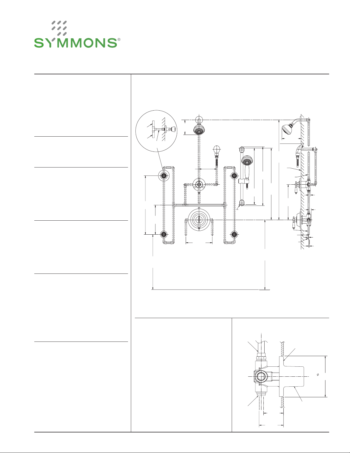
FIGURE 2: WATER DANCE Model 1-7470-X
Dimensions Water Dance Two Wall Shower System, 1-7470-X
Female 1/2'' I.P.S. thread must be recessed 3/8'' (10mm) ± 3/8” (10mm)
from nished wall for proper installation of body spray.
3/4"
3/4"
20"
508mm
1/2"
10"
254mm
approx.
36"
914mm
5"
127mm
approx.
6"-152mm
right or left
381mm
All piping including valve inlets and outlets
3/4" except where noted otherwise.
Male 1/2'' I.P.S. thread must be recessed
1/4'' (6mm) from nished wall for proper
installation of street ell and ange.
15"
25 1/2"
648mm
24 5/8"
625mm
screw bar support
into stud or install
proper backing
approx.
41"
1041mm
1016mm
approx.
30"
762mm
approx.
40"
nished
wall
shower
discharge
hot and
cold inlets
adjustment
6 1/2''
165mm
12''
305mm
2 5/8"
67mm
5/8"
16mm
22mm
1/4''
6mm
1/4"
6mm
7/8"
Pressure Required
Verify that you have adequate flowing (not
static) water pressure before installing a
Water Dance system or High-Flo valve.
For optimum performance we recommend
a minimum of 60 psi flowing pressure to
the High-Flo pressure balancing valve. Also
reducing or eliminating long piping runs and
sharp turns will result in a more satisfactory
performance from the system.
Drain Size
Determine that there is adequate drain size
and capacity to handle the selected Water
Dance system water volume.
The High-Flo valve is capable of delivering
12 gpm at 45 psi. If two valves are to be used
water volumes of up to 24 gpm are possible
depending on available water pressure.
Confirm that the shower drainage system can
handle the anticipated water volume.
oor line
Note: Dimensions subject to
change without notice.
All floor to center dimensions optional. Concealed piping and fittings not furnished by manufacturer.
Install HOT on left and COLD on right
according to valve markings.
FIGURE 1
1) Install piping and fittings with valve body
as shown in Figure 2.
IMPORTANT: Valve rough-in is 2 3/8”
(60mm) min. — 2 7/8” (73mm) max.
from centerline of supplies to face of finish
wall. Install so that surface indicated on
plaster shield on valve is flush with finish
wall as shown in Figure 1.
2) IMPORTANT: Install plug (TTC-295) in
either tub port for shower application or
shower port for tub application.
NOTE: Valve will not work properly with
both ports unplugged.
3) When finishing tile wall remove (pull off;
Page 2
don’t turn) protective plastic shield and
fill area around valve body with grout or
plaster. Do not plaster over SC-2 cap or
service stops.
4) For installation of diverter see installation
instructions included with diverter.
5) Install body spray to the water supply
pipe fitting in the wall; use plumber tape
to seal the connection. Push flange until
flush against finished wall.
NOTE: Any configuration with two or
more body sprays requires that they be
plumbed with a balancing loop as shown
in Figures 2 and 3. This technique insures
that each body spray delivers the same
volume.
6) Turn on hot and cold supplies. Valve will
not operate unless both hot and cold
water are turned on.
7) Adusting Stops - Valve is equipped with a
limit stop screw to be used to limit valve
handle from being turned to excessively
hot water discharge temperatures.
Adjust by removing dome cover, place
handle on stem, open valve to maximum
desired temperature and turn in limit stop
screw until it seats.
WARNING: Failure to adjust the limit
stop screw properly may result in serious
scalding. Shower system may not protect
the user from scalding when there is a
failure of other temperature controlling
devices elsewhere in the plumbing system.
8) Check packing nut (SC-7) for positive
frictional resistance to handle turn
throughout adjustment cycle and at shutoff position, tighten if necessary.
Check valve cap, packing nut and all
valve, pipe and fitting connections for
leaks. Reattach dome cover back onto
packing nut.
9) Push escutcheon (HF-120 or HF-112),
with slot facing downward, and gasket
(HF-129 or HF-130) against wall and
secure to valve with escutcheon screws
(T3-28 or DF-9).
Secure dial (HF-119) to escutcheon (HF-
120).
Mount temperature control handle (T331L or HF-28-LAM) on valve spindle
spline, secure with screw and button.
Install shower arm, flange and shower
head. See Figures 2 and 3.
Install tub spout on stub. Use putty or
sealant on back edge of spout to make
proper seal with finished wall.
10) Allow valve to run in warm position for a
few minutes to flush system. If system is
quite dirty, remove valve spindle or stop
spindles to ensure proper flushing. See
service instructions.
11) Do not install positive shut-off devices
on the outlet of this valve or devices that
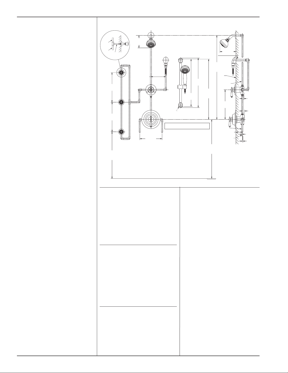
FIGURE 3: WATER DANCE Model 1-7460-X
3/4"
3/4"
1/2"
12"
305mm
12"
305mm
Female 1/2'' I.P.S. thread must be recessed 3/8'' (10mm) ± 3/8” (10mm)
from nished wall for proper installation of body spray.
approx.
36"
914mm
All floor to center dimensions optional. Concealed piping and fittings not furnished by manufacturer.
do not allow the valve to flow at least 1
GPM at 50 psi inlet pressure unless the
inlet supplies of the valve are equipped
with check stops (Suffix: X-CHKS) to
eliminate hot to cold by-pass in the event
the valve’s handle is not turned to off after
use.
Contact your factory representative or
Symmons directly for information on
available checks.
Fiberglass wall installation
When installing the High Flo valve in
fiberglass or panel walls and it is desired
to sandwich wall between valve body and
escutcheon, cut hole in wall as shown in
Figure 4 and mount valve from rear.
Note: It is always recommended to secure
valve piping to rough construction and not
depend on fiberglass wall for valve mounting
security. On panel walls over 1” thick, install
in conventional manner. (See figure 1).
Valve Operation
The main handle of the valve is for control of
temperature only. From the OFF position, the
handle is turned counter-clockwise through
a minimum cold position, through a warm
and hot position for a maximum turn of
approximately one revolution. This allows for
infinite temperature adjustments to suit the
requirements of any user.
5"
127mm
approx.
6"-152mm
right or left
15"
381mm
Male 1/2'' I.P.S. thread must be recessed 1/4''
(6mm) from nished wall for proper
installation of street ell and ange.
25 1/2"
648mm
24 5/8"
625mm
screw bar support
into stud or install
proper backing
All piping including valve inlets and outlets
3/4" except where noted otherwise.
Care and Cleaning
The lustrous finish on your High-Flo valve or
Water Dance system should be treated with
care. It can be readily damaged by improper
handling or abusive treatment.
To clean the finish wipe gently with a soft
damp cloth and lot dry with a soft towel. Use
only a mild soap solution if required.
Do not use abrasive cleaners. Use of polish
abrasive cleaners, solvents or acid cleaners can
damage finish and void Symmons warranty
approx.
30"
762mm
approx.
41"
1041mm
oor line
approx.
40"
1016mm
hot and
cold inlets
6 1/2''
165mm
nished
wall
shower
discharge
12''
305mm
adjustment
2 5/8"
67mm
1/4''
6mm
1/4"
6mm
5/8"
16mm
7/8"
22mm
Page 3

INDIVIDUAL PARTS INDIVIDUAL PARTS COMPOSITE PARTS
C-31 Plaster shield
C-32 Stop spindle assembly
DF-9 Escutcheon screws
DF-10 Handle screw
DF-25 O-ring
HF-106 Cold washer retainer
HF-107 Hot water washer
HF-108 Cold water washer
HF-109 Renewable seat
HF-112 Escutcheon
HF-113 Dome
HF-114 Top seat o-ring
HF-117 Dial
HF-118 Handle flange
HF-119 Dial assembly
HF-120 Escutcheon
HP-17A O-ring
SC-2 Cap
SC-7 Packing nut
SC-10A Hot washer screw
SC-13B Dome cover
SC-17B Packing
SC-18 Lock nut, dome
SC-19 Cap gasket
SC-26 Limit stop with o-ring
T-2 Bottom seat o-ring
T3-28 Escutcheon screws
T-32 Handle screw
T-33 Plug button
T3-31 INS Handle insert
HF-28-LAM Metal finish insert handle:
Handle screw (DF-10)
HF-28-LCF Clear faceted insert handle:
Handle screw (DF-10)
HF-28-LPO White insert handle:
Handle screw (DF-10)
T3-31L Loop style lever handle:
Insert (T3-31 INS)
Handle screw (T-32)
Plug button (T-33)
T3-31S Solid style lever handle:
Insert (T3-31 INS)
Handle screw (T-32)
Plug button (T-33)
Washer & Gasket KIT-HF
HF-106 Cold washer retainer
SC-10A Hot washer screw
HF-107/108 Hot/cold washer
SC-17B Packing
SC-19 Cap gasket
Repair Units
HF-109 Renewable seat unit
complete
HF-103 Spindle
C-31 Plaster shield
FIGURE 5: Parts Breakdown
HF-119
HF-113
T3-31-INS
T3-31L
T-32
T-33
DF-28
DF-10
T3-2 8
HF-120
HF-118
DF-25
SC-1 8
SC-7
HF-117
SC-17B
SC-13B
DF-9
SC-2
HP-17A
T-2
C-32
C-31
HF-106
SC-10A
HF-107
HF-108
SC-1 9
SC-2 6
HF-112
HF-103
FIGURE 4: Fiberglass Wall Installation
HF-114
HF-109
Page 4

SERVICE
1) Shut off water supply to valve.
2) Loosen set screw and remove handle,
dome cover, dial and escutcheon in that
order.
3) Open valve to about warm position and
unscrew cap (SC-2). Warning: Failure
to OPEN VALVE will damage cap and
spindle. Spindle assembly (HF-103) will
be removed with cap. Leave packing nut
(SC-7) in place while unscrewing cap to
avoid distortion.
4) Ordinary service to eliminate dripping
or not shutting off requires only the
replacement of parts supplied in washer
and gasket kit (KIT-HF). Hold spindle
with handle while removing hot washer
screw and cold washer retainer (remove
retainer with channel lock pliers).
5) Inspect surfaces of renewable seat (HF-
109). If seat surfaces are worn or wire
drawn or if NEW SPINDLE IS VERY
LOOSE IN SEAT, replace renewable seat
(HF-109). Use 1/2” hex key. Clean seat
surfaces for proper sealing of top seat
o-ring (HF-114). Tighten seat to 15 foot
pounds of torque.
6) The perforated end of the (HF-109)
spindle assembly houses the balancing
piston which is the heart of this pressure
balancing valve. The piston should be free
to move back and forth and should click
when the spindle assembly is shaken. If
deposits block this action, tap the handle
end of the spindle against a solid object
to free the piston. Soaking in household
vinegar will help free foreign matter. If
this does not free piston, replace (HF-103)
spindle assembly. DO NOT TAMPER
WITH PERFORATED CYLINDER
ON THE SPINDLE ASSEMBLY OR
ATTEMPT REMOVAL OF THE
PISTON.
7) Reassemble, reversing above procedure.
Be sure spindle assembly is drawn close
to the cap before screwing cap back into
valve. Warning: Failure to do this will
damage cap and spindle.
8) USE ONLY SYMMONS SAFETYMIX
GENUINE REPAIR PARTS. FAILURE
TO DO SO WILL VOID ALL
WARRANTIES AND IMPAIR PROPER
OPERATION OF YOUR VALVE.
TROUBLE SHOOTING CHART
Problem Cause Solution (Follow service instructions)
Turn on both supplies. Valve will not
Valve will not pass water Hot and cold water not turned on
Hot and cold washers are worn or foreign
Valve leaks when shut off.
Temperature control handle is turned
from cold to hot (or hot back to cold) and
volume from spout or head is not constant.
Valve delivers sufficient quantity of cold, but
little hot, or the reverse.
Temperature varies without moving handle. Same as above Same as above
Valve delivery temperature reduces gradually
during use; handle must be turned on
to hotter positions to maintain constant
temperature.
matter (solder, chips, etc.) are between
washers and seat surfaces.
Pressure-balancing piston housed in spindle
assembly is blocked from free movement by
foreign matter.
Same as above Same as above
Overdraw on hot water supply, i.e. running
out of hot water.
Symmons Industries, Inc. ■ 31 Brooks Drive ■ Braintree, MA 02184
(800) 796-6667, (781) 848-2250
Website: www.symmons.com
■ Fax (800) 961-9621, (781) 664-1300
■ Email: customerservice@symmons.com
operate unless both HOT and COLD water
pressure is turned on.
Replace HOT and COLD washers. Inspect
top surface on hot and cold seats and
replace if necessary.
With valve open half way, remove handle
and tap spindle with plastic hammer.
If problem not solved, remove spindle
assembly completely and tap handle end
against solid object to free piston. Soaking
in household vinegar will help free foreign
matter.
See note regarding Hot Water Heater on
page 1.
©2007-2014 Symmons Industries, Inc. Printed in U.S.A.
■ ZV-432 ■ Rev A ■ 061114
 Loading...