

SymmetryOffice Align 300 Installation Instructions Manual
Align 300
Installation Ins
tructions
INSTALLATION
WARNINGS:
Read the entire instruction sheet
before you begin
installation
or
assembly.
Installer must
verify
that the
wall will
safely
support the combined weight of all
the attached
equipment and
hardware. Improper
installation
of
this
product can
cause
extensive
property damage
or
serious personal
injury,
either during
or
after
the
installation.
It is
the
responsibility
of
the
installer to ensure that
all
applications including
wood,
concrete,
block, brick, st
eel, etc.
are
secured properly to
code.
California
Installations
could
require specific anchorage,
and additional
mounting screws.
Check with local
authorities
for
codes
in your
area. Other seismic states have
similar regulations.
DISCLAIMER:
The
Manufacturer
and/or
Distributor
will bear no
responsibility
for any damages
of any
kind
arising
from any
impr
oper installation
of this
product.
Because wall construction varies
widely and
the
ultimate
method
of
mounting
is out of
the
Manufacturers
or
Distributors contr
ol,
it is
imperative
that the
installer
consult with
local
engineering,
architectural,
or
construction
personal to ensure
the
wall
mount is
constructed properly
and
to
code to handle
the applied load.
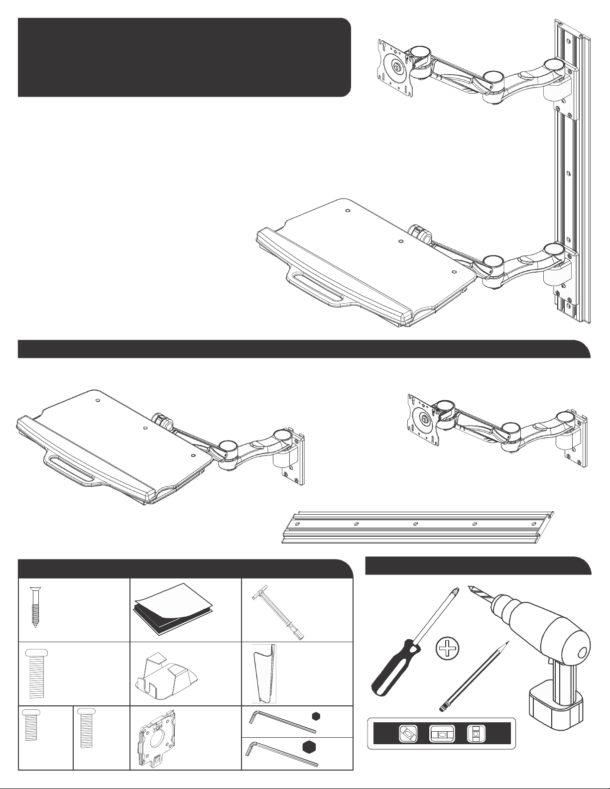
Parts
in Bo
x
Provided Tools
Needed
5x
5x
#12 x 2-1/2
6x
V
elcr
o
T
oggler
B
olts
5x
1/4-20 x 3
1x
Mous
e
House
1x
Track
Cover
4x
M4 x
8mm
4x
M4 x
12mm
1x
Quick
C
onnect
Br
acket
1/8"
3
/16"
154420180
Rev. A

Align 300
Installation Ins
tructions
Slide ke
yboard assembly
on
to track
and
tighten
in
po
sition
with
hand
knob.
Locate
the
wall stud and
mark
the top
hole.
Drill a
pilot hole and
insert
screw part
way.
Place a level
on
the
side of
mount and
mark
other
holes.
Drill
pilo
t
holes. Tighten all screws to
the wall.
1/8˝
NOTE:
Refer to instruction
sheet
included
with
track
for deatils on
different w
all
mounting conditions.
Remove the
end cap at one
top
of
the track slider.
Slide LCD
assembly
on to
track
and
tighten in position
with
hand
knob.
1/8˝
Affix
the
mouse
holder
to the
underside
of
the keyboard tray.
Replace
end cap
and
tighten.
Using
the screws provided
and a
Phillips head
screwdriver, att
ach
the
LCD
to the Quick
Connect
Br
acket.
Slide the
Quick
Connect Bracket on to
the
mounting
plate.
Affix
the 6 Velcro
hook
and loops
to
the underside
of
the keyboard.
Position and
press the ke
yboard
firmly onto
the ke
yboard tray.
*Release Points
Adjusting
the
Height Adjustable Segment:
1.
With
the monitor
mounted to
the
arm, move
the
monitor
through
the
height
range; Ensure the
arm will
hold the
monitor
in
the position
you
placed it.
2. If
the monitor drops
or rebounds upward,
adjust the tension screw
at the
back of
the
arm
segment as
shown
using the
3/16”
Allen key.
Repeat steps
until
the
monitor
is counterb
alanc
ed.
3.
Repeat
for
keyboard tray counterb
alance.
3/16˝
Using the
Height Adjustable
Cable
Manager:
1.
Remove
cable manager
by
pinching
at release points.
2. Lay
cables in
c
able manager.
3. Snap cable manager
back into
place.
Note text indic
ation
“FRONT”
inside
cable
manager.
4.
Repeat
for
keyboard tray cable manager.
 Loading...