


PR Series
Precision Toploading Balances
USER MANUAL
(
Software Revision: 2.35)
P.N. 8190, Revision A1, September 2006

Page 2 of 32
P.N. 8190, Revision A1, September 2006

Page 3 of 32
P.N. 8190, Revision A1, September 2006
CONTENTS
1.0 INTRODUCTION ..........................................................................................................4
2.0 TECHNICAL SPECIFICATIONS...................................................................................5
3.0 UNPACKING THE BALANCE.......................................................................................6
4.0 LOCATING THE BALANCE..........................................................................................6
5.0 SETTING UP THE BALANCE ......................................................................................7
5.1 ASSEMBLING THE BALANCE .............................................................................7
5.2 LEVELLING THE BALANCE.................................................................................7
5.3 WARM-UP TIME ...................................................................................................7
6.0 DISPLAY...................................................................................................................8
7.0 KEYPAD.......................................................................................................................9
7.1 NUMERIC ENTRY METHOD................................................................................9
8.0 INPUT/OUTPUT .........................................................................................................10
9.0 OPERATIONS............................................................................................................11
9.1 INITIALISATION..................................................................................................11
9.2 PASSCODES......................................................................................................11
9.3 WEIGHING..........................................................................................................12
9.3.1 Weighing Units.............................................................................................12
9.4 FUNCTIONS........................................................................................................13
9.4.1 Parts Counting..............................................................................................13
9.4.2 Percent Weighing.........................................................................................14
10.0 CALIBRATION..........................................................................................................15
11.0 RS-232 INTERFACE ................................................................................................16
12.0 ERROR CHECKING.................................................................................................19
13.0 SUPERVISOR MENUS ............................................................................................20
13.1 ENABLE WEIGHING UNITS...............................................................................20
13.2 ENABLE WEIGHING MODES.............................................................................21
13.3 ENABLE SERIAL INTERFACE PARAMETERS..................................................21
13.4 SETUP PARAMETERS.......................................................................................23
13.5 CALIBRATION SETUP........................................................................................24
13.6 PASSCODES......................................................................................................25
13.6.1 Forgotten Passcodes ...................................................................................25
14.0 SAFETY AND MAINTENANCE ................................................................................26
15.0 TROUBLE-SHOOTING.............................................................................................26

Page 4 of 32
P.N. 8190, Revision A1, September 2006
1.0 INTRODUCTION
Thank you for selecting the Precision Balance.
This Instruction Manual will familiarise you with the installation, trouble-
shooting, general maintenance of the balance, etc. and will guide you through
the various applications.
Please read this Manual thoroughly before starting the operation. If you need
any clarifications, feel free to contact your supplier.
PRODUCT OVERVIEW
This Precision Balance is ideal for laboratory and general purpose weighing.
FEATURES:
• Large easy to read LCD display with backlight
• Applications include weighing, parts counting and percentage
weighing
• External calibration
• Bi-directional RS-232 interface
• Can be configured to print a GLP Compliant report after each
calibration to include the time, date, balance number and a
verification of the calibration
• Automatic temperature compensation
• Display in 4 languages- English, French, German and Spanish
• Multiple weighing units
• Date and time
• Easy to use, sealed keypad
• Below balance weighing facility
• Password protection
• Security locking point
• Robust metal casing

Page 5 of 32
P.N. 8190, Revision A1, September 2006
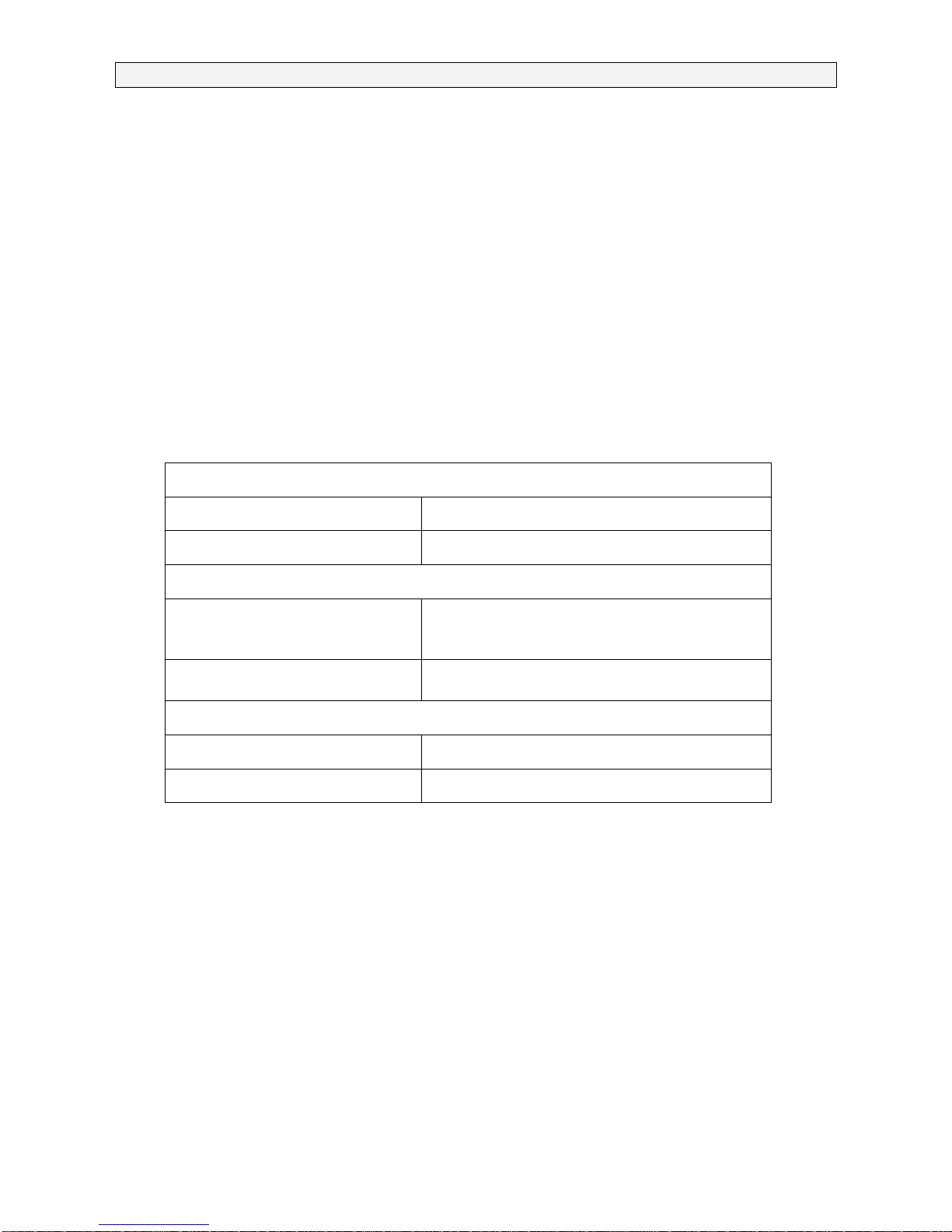
2.0 TECHNICAL SPECIFICATIONS
210g model 410g model 2200g model 4200g model
Maximum
capacity
210g 410g 2200g 4200g
Readability 0.001g 0.01g
Typical
Repeatability
0.002g 0.02g
Linearity (±) 0.003g 0.03g
Tare range Full
Units of
measure
grams, milligrams, kilograms, carats, pennyweights, grains,
troy ounce, ounces
Interface RS-232 bi-directional
Operating
temperature
10°C - 40°C
Power supply 15 VDC, 50/60 Hz, 800 mA
Calibration External
(Selectable automatic calibration due to change in time or temperature)
Display Backlit LCD with dual digits (24 mm high)
Draught
shield
Supplied as standard for 0.001g units
Housing Die cast aluminium housing
With glass draught shield (for 0.001 g units)
Pan size 140 mm x 140 mm /
5.5” x 5.5”
200 mm x 175 mm /
7.9” x 6.9”
Overall
dimensions
(w x d x h)
251 × 358 × 104 mm /
10” x 14.3” x 4.2”
Net weight 5.5 kg / 12 lb
Applications Weighing, Parts counting, Percentage weighing
Page 6 of 32
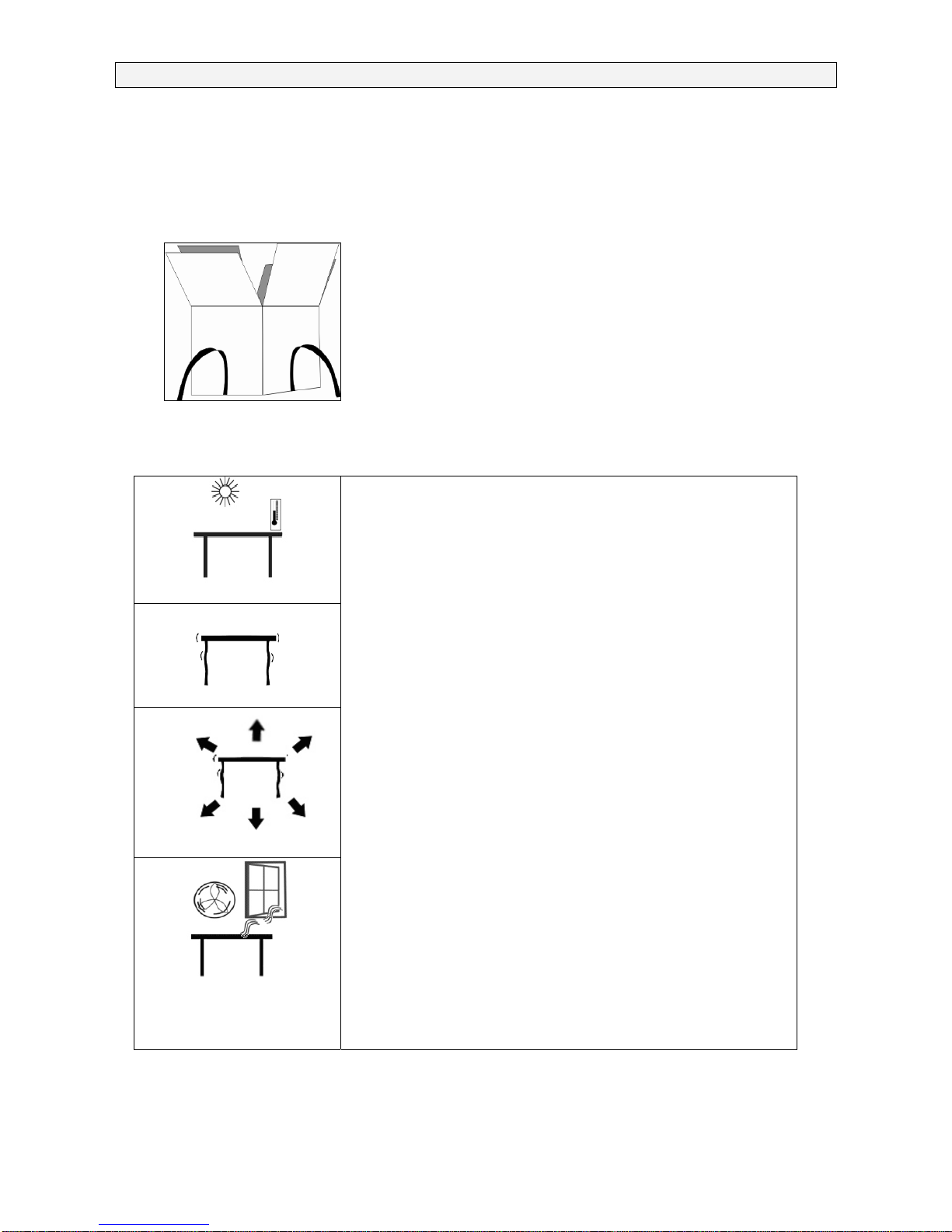
3.0 UNPACKING THE BALANCE
Remove the balance from the packing by carefully lifting it out of the box.
Inside the box you will find everything needed to start using the balance-
AC adapter
Four plastic pan supports
Stainless Steel Top Pan
Breeze / draught shield (For 0.001g models)
This User Manual
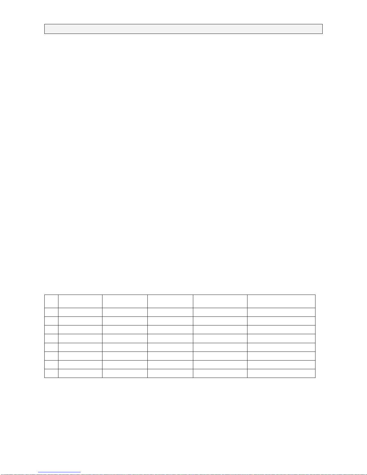
4.0 LOCATING THE BALANCE
• The balance should not be placed in a
location that will reduce the accuracy.
• Avoid extremes of temperature. Do not place
in direct sunlight or near air conditioning
vents.
• Avoid unsuitable tables. The table or floor
must be rigid and not vibrate.
• Avoid unstable power sources. Do not use
near large users of electricity such as welding
equipment or large motors.
• Do not place near vibrating machinery.
• Avoid high humidity that might cause
condensation. Avoid direct contact with water.
Do not spray or immerse the balances in
water.
• Avoid air movement such as from fans or
opening doors. Do not place near open
windows or air-conditioning vents.
• Keep the balance clean. Do not stack material
on the balances when they are not in use.
P.N. 8190, Revision A1, September 2006

Page 7 of 32
5.0 SETTING UP THE BALANCE
5.1 ASSEMBLING THE BALANCE
• Locate the balance on a solid surface, free from vibration
• Gently place the 4 pan supports (if not already fitted) and then the
stainless steel pan on the weighing platform
• Place the windshield frame and the top cover around the pan (for
0.001g models)
• Level the balance using the adjustable feet and spirit level
• Connect power to the balance
• For best performance, let the balance warm up for 30-60 minutes and
calibrate before using
5.2 LEVELLING THE BALANCE
After placing the balance in a suitable place,
level it by using the spirit level on the rear of the
balance. To level the balance turn the two
adjustable feet at the rear of the balance until
the bubble in the spirit level is centred.
5.3 WARM-UP TIME
Attach the power supply cable to the connector
on the rear of the balance. Plug the power
supply module into the mains. The display will
indicate the balance serial number (if set) and
the software revision number followed by the
capacity of the balance. Next the balance will
run a self-test by displaying all segments and
then will show zeroes accompanied by the zero
symbol. If the balance serial number is not set,
the display will show dashes.
Before you start weighing, you have to wait for the balance to achieve a
stable internal temperature. Typical initial warm-up time suggested for a
balance already at room temperature is about 1 hour.
A stable sign ~ is shown when the balance is in
stable condition. It will turn off if the balance is
not stable. Exact zero is shown when the
“0“
symbol is on to the left of the display area.
P.N. 8190, Revision A1, September 2006

Page 8 of 32
6.0 DISPLAY
This display includes areas for the weight value (up to 7
digits), symbols for common weighing units, tare, stability, zero
and low battery and a text area for menu.
The LCD has 7 x 7-segment digits for the weight and 10 x 14 segment digits for messages, symbols for weighing units and
indicators such as stability etc.
The 14 segment digits area is used to display messages
concerning operation or errors.
The 10 digit text area is used to display the current weighing
mode or to guide the user through the operation.
SYMBOLS AND INDICATORS
The LCD has unique symbols to indicate the following:
0
Zero
Stable
g, oz, ozt, GN, dwt,
ct, Kg, mg, Pcs, %
Text is shown for the weighing units and
modes
“CAL”
When calibration is occurring or about to occur
“ºC”
When a temperature is shown or a calibration
is requested due to change in temperature
“ti”
For a time driven calibration
“Net”
When a net weight is shown
P.N. 8190, Revision A1, September 2006

Page 9 of 32
7.0 KEYPAD
The keypad has the following keys to operate the balance.
Keys Primary function Secondary function
[On/Off] To turn the balance to ON or
OFF
-
[Tare] or [Esc] A combined zero and tare
function
To escape from setup
functions and modes
[Cal] / or
[Up]
Starts the calibration function To increment or change a
displayed value or scroll
through options forward
[Print] / or
[Back]
Instructs the balance to print
data
To advance a flashing digit
by one position to the left
[Setup]/
or [Enter]
Enters a function To save a value during
setting up a function such
as entering unit weight
[Mode] / or
[Advance]
Selects functions by cycling
through a set of enabled
functions, for example parts
counting or percent weighing
To advance a flashing digit
by one position to the right
To go back by one step
during setup functions
[Units] / or
[Down]
Selects weighing units by
cycling through a set of
enabled units
To decrement or change a
displayed value or scroll
through options backwards
[Mode] / or
[Advance]
Selects functions by cycling
through a set of enabled
functions, for example parts
counting and percent weighing
To advance a flashing digit
by one position to the right
To go back by one step
during setup functions
7.1 NUMERIC ENTRY METHOD
To set a value when required, use the keys as given below-
- [Up] and [Down] keys to increase or decrease the flashing digit,
- [Advance] and [Back] keys to advance or move back the digit and
- [Enter] key to accept the value
P.N. 8190, Revision A1, September 2006

Page 10 of 32
8.0 INPUT/OUTPUT
The rear panel has connectors for RS-232 serial and
buffered I
2
C-bus interfaces and a power input socket.
Required power input is a low-voltage external supply,
15VDC @ 800mA.
Various communication options, e.g. USB, LAN, Wireless,
will be implemented in the future via add-on “black-boxes”
which will convert the RS-232 serial output or I
2
C to the
desired protocol. The basic unit includes RS-232 serial
communications only.
P.N. 8190, Revision A1, September 2006

Page 11 of 32
9.0 OPERATIONS
9.1 INITIALISATION
When the balance is first switched on, it
will display the balance serial number (if
set), software revision, model capacity
and then all segments on the display will
be shown. Overall the time taken is
usually 5 -10 seconds.
If a passcode has been set, the display will show “PASSCODE” and the main
display will show a zero. In this case you must enter the passcode to
continue using the numeric entry method (see section 7.1). A different
passcode may be set for a Supervisor to weigh or to have access to the
selected User menus. If the passcode has not been set the balance will
continue as below.
The display will show zero reading along
with the zero symbol “
0” and the
weighing unit last used. If automatic
time calibration is enabled the balance
will calibrate after power up and again
after the pre-set time interval.
9.2 PASSCODES
If a passcode has been set to limit access to the weighing functions of the
balance the display will show “PASSCODES” with the main digit set to zero.
The display will change to show 7 digits set to zero with the rightmost digit
flashing. Use the numeric entry method (see section 7.1) to enter the code. It
will be necessary to enter the correct passcode to continue. See the Section
13.6 for details.
P.N. 8190, Revision A1, September 2006
Page 12 of 32
P.N. 8190, Revision A1, September 2006
9.3 WEIGHING
• Press [Tare] to zero the balance, if required
• “0 “ will be displayed
• Place a mass on the pan and the weight will be displayed
• If a container is used press [Tare] to tare the balance when the stable
symbol “~” is on. “Net” will be displayed to indicate that the balance is
tared
• When the display shows zero, place the item to be weighed. Only the
net weight will be displayed
• At any time the [Units] key can be pressed to select another unit. Use
the [Up] or [Down] key to scroll through the units and select the desired
unit by pressing [Enter], the display will change to show the weight in
the selected weighing unit. The available weighing units can be enabled
or disabled by the user (see section 13.1). Only weighing units that
have been enabled will be cycled through when [Units] is pressed
9.3.1 Weighing Units
You can select alternative weighing units to display the weight by pressing
the [Units] key. The common weighing units are:
Unit Symbol Models Conversion Factor
1g =
Conversion Factor
1 unit = grams
1. Grams g All 1 1.0
2. Milligrams mg not 0.01g units 1000 0.001
3. Kilograms kg All 0.001 1000
4. Carats ct All 5 0.2000
5. Pennyweights dwt All 0.643014865 1.555174
6. Grains GN All 15.43236 0.0647989
7. Troy ounces ozt All 0.032150747 31.103476
8. Ounces oz All 0.035273962 28.349523
It is possible to set the balance to display only grams. Grams will always be
one of the units enabled, by default.

Page 13 of 32
P.N. 8190, Revision A1, September 2006
9.4 FUNCTIONS
When weighing, the user can access the applications that have been enabled
(see section 13.2).
The following applications are available in this version (2.35):
• Parts counting
• Percent weighing
The functions can be enabled or disabled using a similar method to the Units
above by turning the functions to on or off.
9.4.1 Parts Counting
A known quantity of sample is first weighed to compute an average unit
weight and then an unknown quantity of the sample is weighed. The net
weight of this unknown sample is divided by the average unit weight to
display the quantity. The result is always a whole number.
The balance will have a preset number of parts to be used as a sample.
These values are 10, 25, 50 or 100 items.
• Press [Mode] to show parts counting, “PARTS” will be displayed
• Enter parts counting by pressing [Enter]
• Press the [Up] or [Down] key to select the sample size, “REF QTY”,
10, 25, 50, 100, etc., then press [Enter] to confirm
• When “LOAD XX Pcs” is shown place XX number of items on the pan
and press [Enter] to compute the average piece weight
• Remove the sample when display shows “XX Pcs” and then place an
unknown quantity on the pan. The balance will then compute the
number of parts based upon the average piece weight. The display will
show the result in Pcs
• To count another item press [Mode] and continue as before
• Checks will be made to determine that the weight of the reference parts
is large enough for reasonably accurate counting (weight of each piece
should be > 1d)
• To return to normal weighing, press [Mode] to show “REF QTY” then
press [Esc]

Page 14 of 32
P.N. 8190, Revision A1, September 2006
9.4.2 Percent Weighing
Percent weighing is carried out by defining a sample weight as 100%. The
sample weight can either be entered by the user or taken from a sample
• Press [Mode] and then the [Up] or [Down] key to select Percent
weighing, “PERCENT” will be displayed
• Press [Enter] to enter the function
• Display will show, “PERCENT SAMPLE”
• Press [Enter] to select the sample method
• When “LOAD 100 %“ is shown, add the sample
• Press [Enter] to set this weight to be 100%. When ready the display will
show “100%”
• Remove the sample and place an unknown sample to display the
percentage weight
• To set another weight as 100%, press [Mode] and continue as before
• To manually enter a value to be set as 100%, press [Up] or [Down] key
when “PERCENT SAMPLE” is shown to select “PERCENT Ent Wt”
• Press [Enter] to select the manually entered weight method
• Enter the weight using the numeric entry method (see section 7.1)
• Place unknown sample to display the percentage weight
• To perform percent weighing with another sample press [Mode] and
continue as before
• To return to normal weighing, press [Esc]
Note: Percentage will be displayed to the maximum number of decimal
places based on the resolution of the balance. To increase or decrease by
one decimal place, press the [Up] or [Down] key respectively.

Page 15 of 32
P.N. 8190, Revision A1, September 2006
10.0 CALIBRATION
The balances are calibrated using an external mass.
• Press the [Cal] key to start calibration.
• Pressing [Esc] will abort the calibration at any time
• Check the display is at zero. Tare, if necessary
• Press the [Cal] key
• Display will show “LOAD 0”. Ensure the pan is empty and press [Enter]
• The balance will then show the value of the calibration mass required,
for example “LOAD 2000 g”
• Place the suggested mass on the balance. Press [Enter] to continue
• When the calibration is complete, balance will return to normal weighing
The balance will have the ability to ask for calibration when the following
conditions occur. This feature can be enabled or disabled by the user (see
section 13.5). The conditions are:
1. Internal temperature change greater than a preset amount, typically 2ºC
2. Time since last calibration exceeds a preset time, typically 4 hours or 15
minutes after power is applied
The user will know a calibration is asked for from flashing of the “CAL” symbol
on the display. The display will show a 5 second countdown when calibration
will start. If the user presses the [Esc] key the calibration will be delayed by
one minute to allow for a process in progress to be finished. As soon as the
balance is calibrated the symbol will be turned off.
Suggested calibration weights
210g model 200g
410g model 200g
2200g model 2000g
4200g model 2000g
Calibration Errors
Occasionally during calibration an error will be detected. These errors can be
caused by unstable readings, improper weights being used, large shifts of
zero from the factory settings, etc. When an error is found a message will be
shown and the calibration must be done again.

Page 16 of 32
P.N. 8190, Revision A1, September 2006
11.0 RS-232 INTERFACE
The balances have the ability to send data to the serial interface.
The weighing data can be sent over the interface either automatically or when
the user presses the [Print] key.
The user has control over what data is to be printed.
The following gives a description of the RS-232 interface.
HARDWARE
The RS-232 interface is a simple 3 wire connection. The input and output
connections are:
Connector: 9 pin D-sub miniature socket
Pin 2 input to balance RXD
Pin 3 output from balance TXD
Pin 5 Signal ground GND
Handshaking is not applied.
Baud rate: 4800, 9600, 19200, 38400
Parity: NONE (=8N1), EVEN (=7E1) or ODD (=7 O 1)
All lines are terminated with carriage return and line feed (<CR><LF>).
In continuous output mode, or if single-line output on demand is selected, the
serial output format will be a single line in the form “1234.567 g<CR><LF>”.
The format of the single-line output will change depending on the mode in
which the balance is operating, as described below.
If output on demand is selected, the user may optionally configure the serial
output as a choice of 3 styles of form, either in a default format or in one of
two custom formats. Each of the custom formats can be configured to output
up to 15 lines of data. The data types that can be printed are:
NAME TEXT PRINTED
ID number ID no.: xxxxxxxxxxxx
Serial number Serial no. xxxxxxxxxxxx
Date DATE dd/mm/yyyy
Time TIME hh:mm:ss
Net weight Net: xxx.xxx g
Gross weight Gross: xxx.xxx g
Page 17 of 32
Tare weight Tare: xxx.xxx g
Unit weight Unit wt: xxx.xxx g
Count Count: xxxx pcs
Reference weight Ref. wt: xxx.xxx g
Percent Percent: xx.xxx %
A blank line printed <CR><LF> only.
Any of these can be printed on any of the 15 lines available. Not all items
need to be used and any one can be used more than once (see section 13.3).
The data for each form will be preceded by a start-of-header <SOH>
character (01) and terminated with an end-of-transmission <EOT> character
(04). These characters will be ignored by a serial printer but will allow a
computer program which reads the data to distinguish between this block
report format and the single-line output format described above.
STANDARD FORMAT
The balance will print the following data as the standard form. The standard
form cannot be changed. The format of the custom forms #1 and #2 will be
the same as the standard form until modified by the user.
Line 1 Date
Line 2 Time
Line 3 Blank line
Line 4 ID number
Line 5 Blank line
Line 6 Result
Line 7 Blank line
Line 8 Blank line
This will result in a printout that looks like:
Date: 23/09/04
Time: 15:45
ID No: 123456
Net: 123.456 g
*NOTE: The format of the results line will change depending on the mode in
which the balance is operating, e.g.
Normal weighing: “123.456 g”
Parts Counting: “1234 pcs”
Percent weighing: “12.345 %”
P.N. 8190, Revision A1, September 2006
Page 18 of 32
P.N. 8190, Revision A1, September 2006
INPUT COMMANDS USING REMOTE KEYS
The balance can be controlled with the following commands sent using
remote keys such as from a PC. The commands must be sent in upper case
letters, i.e. “KT” not “kt”. Press the Enter key of the PC after each command
(the action of Carriage Return is denoted as <CR> as shown below).
Basic Input Commands:
!KT<CR>
Tares the balance to display the net weight. This is the same as pressing
the [Zero / Tare] key when the balance is in the normal weighing mode.
!KS<CR> Enters the Setup section. This is the same as pressing the [Setup] key
when the balance is in the normal weighing mode.
Once entered the Setup section, the balance can be controlled remotely
using the Input Commands (as mentioned in this table) which will perform
the same key functions as described in section 13.0.
!KP<CR>
Transmits data over RS-232 interface. This is the same as pressing the
[Print] key when the balance is in the normal weighing mode.
!KM<CR> Enters the Modes section. This is the same as pressing the [Mode] key
when the balance is in the normal weighing mode.
!KC<CR> Enters the Calibration section. This is the same as pressing the [Cal] key
when the balance is in the normal weighing mode.
!KU<CR> Enters the Unit selection section. This is the same as pressing the [Units]
key when the balance is in the normal weighing mode.
Invalid Input Command:
If an invalid command is received, then the command is returned as follows-
Invalid Command Message returned Remarks
!NT<CR> !EU<CR> Command character is not ‘K’
!KK<CR> !EK<CR> Key charac ter is not ‘T’, ‘S’, ‘P’, ‘M’, ‘C’
or ‘U’
!KT-<CR> !EF<CR> Command format error, <CR> is not
the fourth character
KT<CR> or
!KT -
No reply Either ‘!’ or <CR> is missing in the
command string
Page 19 of 32
P.N. 8190, Revision A1, September 2006
12.0 ERROR CHECKING
During weighing the balance is constantly checking to see if the balance is
operating within the limited parameters. The errors likely to occur are:
A/D counts below lowest allowed value
A/D counts above highest allowed value
A/D not operating
Maximum capacity exceeded
Other errors may be detected during special functions or operations. These
will be described in the section that applies.
Error messages and the reasons are:
Concerning A/D counts
ERROR ADc UL A/D counts below a limit
ERROR ADc OL A/D counts above a preset limit
Concerning calibration
ERROR St
Calibration could not be completed
because the results were not stable
ERROR LO or ERROR HI
Calibration constant not within 20% of old
calibration constant
Concerning weighing
ERROR LO Weight display is below zero by >4%max
ERROR HI Weight is above maximum plus 90d

Page 20 of 32
P.N. 8190, Revision A1, September 2006
13.0 SUPERVISOR MENUS
Pressing the [Setup] key while in normal weighing gives access to the
Supervisor menus.
• When [Setup] is pressed and passcodes are not enabled, the display
will show the message “SUPERVISOR”. If passcodes are enabled, the
balance will ask for it by displaying “PASSCODE 0”
• If a wrong code is entered an “ERROR CODE” message will flash and
the balance will return to weighing mode
• If the passcode has been enabled and entered, the balance will allow
the operator to access the Supervisor’s menus
• When the display shows “SUPERVISOR”, press [Enter] to view the
parameters that can be modified
• From this menu the user can enable/disable weighing units or modes,
set balance parameters for the conditions, set time and date, set
parameters for the RS-232 interface, calibration parameters and
security parameters
• The [Up] and [Down] keys will cycle through the main parameters,
pressing the [Enter] key will enter the parameters and sub-parameters
or options can be set. Press [Mode]
to come out of a sub-parameter
or press [Esc] to return to normal weighing from any parameter
13.1 ENABLE WEIGHI NG UNITS
• When “UNITS” is displayed, press [Enter]. The display will show the
symbol for the first unit, e.g. carats, ct, together with its enable state
“OFF” or “On”. The user can then enable or disable the carats unit by
using [Up] or [Down]. Pressing [Enter] will confirm the setting and will
advance to the next weighing unit. Repeat for each weighing unit in
turn. Gram is always set to “On”
• Press [Mode] to advance to setting of the next menu or press [Esc] to
return to normal weighing

Page 21 of 32
P.N. 8190, Revision A1, September 2006
13.2 ENABLE WEIGHI NG MODES
Same steps are followed to enable or disable the weighing modes.
• Press [Enter] when “MODES” is displayed. The display will show the
first mode i.e., Parts Counting (“PARTS”) together with its enabled state
“OFF” or “On”. The user can enable or disable the parts counting mode
by using [Up] or [Down]. Pressing [Enter] will confirm the setting and
will advance to the next weighing mode. Repeat for each mode in turn
• Press [Mode] to advance to setting of the next menu or press [Esc] to
return to normal weighing
13.3 ENABLE SERIAL INTERFACE PARAMETERS
The parameters affecting the serial setup are set in a similar manner to the
other parameters.
Press [Enter] when “SERIAL” is displayed to enter the sub-menu.
The parameters that can be set are:
ENABLE The serial port can be set to On or OFF
BAUD RATE Set the Baud Rate to 4800, 9600, 19200 or 38400
PARITY
Set the Parity to NONE, EVEN or ODD
STABLE To print when stable (On) or regardless of stability
(OFF)
CONTINUOUS Set the RS-232 to send data continuously to On or OFF
PERIODIC Set the RS-232 to send data periodically (set in
seconds) to On or OFF. If On is selected, the value can
be changed between 1 and 999 seconds, using [Up]
and [Down]
FORMAT
To send data as a single line of data, using the standard
format or using a customer designed format (FORM 1 or
FORM 2).

Page 22 of 32
P.N. 8190, Revision A1, September 2006
Format of custom forms #1 and #2
If FORM1 or FORM2 is selected, it can be changed by the user using a
selection of available data. By default the 2 forms are the same as the
standard form unless changed by the user as below.
When FORM 1 or FORM 2 is selected the user can set the information to be
printed on each line of the form. Pressing the [Up] or [Down] keys will cycle
through the options available. The options are:
INST ID Instrument ID number
SER No Serial Number
TIME Time
DATE Date
NET Net Weight (Gross weight – Tare Weight)
GROSS Gross Weight
TARE Tare Weight
UNIT Unit weight in parts counting mode
COUNT Number of items in parts counting mode
REF 100% weight in percent weighing mode
PERCENT Percentage of reference weight in percent weighing
Cr Lf Inserts a blank line
END Signifies the end of the report
When END is entered the display returns to the RS-232 Sub-menu
Enter the data to be printed on the first line by pressing the [Up] or [Down]
key to cycle through the options. If the current information is OK then press
the [Setup]/Enter key to move to the next line.
e.g. “LINE No1” “DATE” - prints date
Select a code for one of the preset data formats as detailed above.
The next line shows: “LINE NO 2” “TIME” - prints time
Only one item can be entered per line.
Continue until the formatting of the form is complete. There are 15 lines of
possible data. After the 15
th
line has been set or “END” has been selected,
the balance will return to the RS-232 Sub-menu.
Press [Mode] to advance to setting of the next menu or press [Esc] to return
to normal weighing.

Page 23 of 32
P.N. 8190, Revision A1, September 2006
13.4 SETUP PARAMETERS
The user parameters that control the balance are shown under the SETUP.
When “SETUP” is displayed, press the [Setup]/Enter key. The options for
each parameter can be scrolled through by using the [Up] or [Down] key.
LANGUAGE
English
French
German
Spanish
TIME Set Time using the numeric entry
method (see section 7.1)
DATE DATE FORM
EUROPE (dd/mm/yy)
USA (mm/dd/yy)
Set Date using the numeric entry
method (see section 7.1)
INST ID Enter a user number to identify this
balance
BUZZER
On= Enable
OFF= Disable
BACKLIGHT
On
OFF
AUTO
POWER DOWN
Set the time after which the unit will go
into Stand-by power settings,
On=Enable, OFF=Disable, If set to On-
the options are 1 to 9 minutes
FILTER
Set a value for the amount of filtering to
be done, set a value of 5, 10, 20, 30,
40 or 50. A larger number is more
filtering and a slower response. Default
is 20
STABILITY
Set a value to be used to determine
balance stability, set a value of 1, 2, 5
or 10d. A larger number corresponds to
a larger stable zone. Default is 5
AUTO ZERO Can be set to On or OFF to enable the
auto-zero function. If set to On- select
from 1, 2 or 5d

Page 24 of 32
P.N. 8190, Revision A1, September 2006
The sub-menu is entered by pressing [Enter] –
• Use the [Up] and [Down] keys to increase or decrease the value for
setting. Press [Enter] to accept the setting and advance to the next
item in the menu
• Press [Mode] to advance to setting of the next menu or [Esc] to return
to normal weighing
13.5 CALIBRATION SETUP
This menu allows the user to set the calibration parameters.
• Press [Enter] when “CAL SETUP” is displayed to select the calibration
parameters
• The options for each parameter can be scrolled through by using the
[Up] or [Down] key
ENABLE NO =operator calibration is disabled
YES=operator calibration is enabled
CAL REPORT On = Enabled. Prints out Calibration
report after successful calibration
OFF = Disabled
TIME CAL On = Enabled. Select time from 1 to
24 hours. Default setting is 4 hours
OFF = Disabled
TEMP CAL On = Enabled. If set to On, set the
temperature variation from 0.2 to 4°C
OFF = Disabled
Press [Mode] to advance to setting of the next menu which is
“PASSCODES” or [Esc] to return to normal weighing.

Page 25 of 32
P.N. 8190, Revision A1, September 2006
13.6 PASSCODES
To enable the security features in this balance it is necessary to set
passcodes. There are 2 passcodes called Operator Passcode and Supervisor
Passcode. The Operator Passcode allows an authorised user to operate the
basic weighing functions of the balance but will not allow access to the
Supervisor Menus if the Supervisor Passcode has been set.
To change or disable a Passcode it will be necessary to enter the current
passcode.
Press [Enter] when “PASSCODES” is displayed to enter this section.
OPERATOR Enter the current passcode (OLD) first
then enter a new passcode if desired.
A passcode set to zero will disable the
security feature and allow unlimited
access.
SUPERVISOR Enter the current passcode (OLD) first
then enter a new passcode if desired.
A passcode set to zero will disable the
security feature and allow unlimited
access.
13.6.1 Forgotten Passcodes
Keep a record of the passcode to ensure you can access this section again.
If however you have forgotten your passcode you can still gain access by
entering a universal code.
If you have forgotten the current passcode a code of “15” will always allow
you to enter the Supervisor area.
Using the Supervisor menus go to the PASSCODE section and reset the
operator or Supervisor passcode using the “15” code as the old number when
asked.

Page 26 of 32
P.N. 8190, Revision A1, September 2006
14.0 SAFETY AND MAINTENANCE
CAUTION
Use the AC adapter designed by the manufacturer for the balance. Other
adapters may cause damage to the balance.
Avoid overloading or dropping material onto the platform which could damage
the balance.
Do not spill liquids on the balance as it is not water-resistant. Liquids may
damage the case and if it gets inside the balance it may cause damage to the
electronics.
Material that has a static electric charge could influence the weighing.
Discharge the static electricity of the samples, if possible. Another solution to
the problem is to wipe both sides of the pan and the top of the case with an
anti-static agent.
15.0 TROUBLE-SHOOTING
Service of this Precision Balance will generally be necessary when the
balance does not perform as expected. The balances are not userserviceable. For Service Information, see section 18.0 and contact your
supplier.
Problems usually fall into one of the following categories:
User Problems:
The user is asking the balance for something it cannot do or is confused by
the modes and functions of a balance. It is also possible the user has set a
parameter that has affected the balance operation. Resetting the parameter
to a normal value will restore operation.
Mechanical Problems
The balances consist of complicated and fragile mechanical devices. They
can be damaged by placing a weight on it which is too high for the balance or
by dropping the balance or occasionally shipping it without taking care. The
most fragile parts are the flexures. Dust, dirt, spills and other foreign objects
in the balance can also cause problems.

Page 27 of 32
P.N. 8190, Revision A1, September 2006
Electronic Problems:
These are the rarest of the problems affecting balances. If an electronic
problem is suspected make sure the mechanical problems that can cause
similar symptoms have been eliminated before attempting electronic repairs.
With the exception of cables most electronic repairs are solved by board
replacement.
The table that follows is a guide of common problems and their solutions.
Note that many problems may have multiple solutions and there may be
problems found that are not listed in the table. For Service Information,
contact your supplier.
BALANCE DOES NOT FUNCTION
The balance is dead
when power is applied
Power supply failure Check adapter is working
Check adapter is correct for the balance
Normal adapter is 15VDC, 800mA.
Power supply circuit board failure
Short circuit on any circuit board
The display does not
turn on but the
calibration motor
moves when power is
applied
Power is getting to
balance, display is not
working
Check display cables
Replace display module
The display stays on
the initial test screen
when power is applied.
Calibration weight
motor is on.
Unstable balance
Balance not working
correct
Power supply
Check if balance is stable by using
service menu and view A/D values
Put breeze shield over pan
Check power supplies
BALANCE WORKS BUT IS NOT STABLE
Balance is unstable by
a few divisions
Noise or vibration
from environment
Friction in mechanics
Check the balance is positioned
correctly to avoid vibration, wind or air
movement, it is on a solid table, It is not
near sources of heat or cool air,
Check balance with weights if problem
occurs when sample is used. Static
electricity on the samples can cause
drifting and instability.
Check the area around the weighing
pan for hair, dust, obstructions under
the pan,
A complete inspection of the mechanics
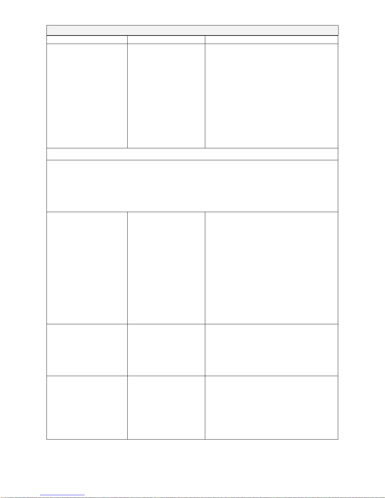
Page 28 of 32
P.N. 8190, Revision A1, September 2006
to look for sources of friction.
Balance is very
unstable and does not
weigh correctly
Mechanical problems
Balance programming
Electronic problems
A complete inspection of the mechanics
to look for sources of friction.
Verify the A/D is also unstable. If the
A/D is OK then suspect the
programming of the balance. Reset
parameters, check temperature
compensation, and redo the calibration.
Some electronic problems can also
cause this. But all mechanical problems
must be resolved first.
BALANCE IS NOT ACCURATE
You must have accurate and trusted weights to test a balance. If you suspect that the
balance is not accurate then you must know your weights are accurate. A balance
calibrated using a bag of flour is not accurate even if it works OK otherwise.
Balance is not accurate Repeatability
Eccentric loading
Linearity
Verify the balance shows the same
value when the same mass is placed on
the centre of the pan for a few tests.
Verify the balance shows the same
reading (within a tolerance depending
upon the model) when a mass is placed
at positions around the pan.
Verify the balance is acceptable
throughout the weighing range. The
balance must give acceptable readings
from low weights up to the capacity.
Poor Repeatability Usually a mechanical
problem.
Inspect the area around the pan for hair,
dust or other obstructions,
Inspect he mechanics for any possible
problems.
Poor Eccentric loading A mechanical problem Inspect the area around the pan for hair,
dust or other obstructions,
Inspect he mechanics for any possible
problems
Readjust the Eccentric loading

Page 29 of 32
P.N. 8190, Revision A1, September 2006
Poor Linearity Usually a mechanical
problem
Electronic Problems
Re-check repeatability
Inspect the flexures for damage or loose
hardware
Use the Linearity Function in the service
menu to reset linearity
A problem in the analogue circuit board
or power supplies can cause poor
linearity. Make sure all mechanical
problems have been eliminated first
OTHER PROBLEMS:
Cannot calibrate Zero shifted more
than allowed
Calibration timeout
Check all flexures for damage
Reset factory calibration
Verify linearity and repeatability
The balance may be unstable. Verify
stability as above. Try using a more
aggressive filter
Calibration weight
motor does not stop
Check the cables to the motor, try
plugging the balance into the power
again
Look for friction in the calibration weight
movement
Check the flags that control motor
position are correct
RS-232 not working Doesn’t print Check parameters match the device
connected
Verify cable is correct
RS-232 circuits damaged
Display dark, keys
beep
Display contrast poor
Cable unplugged or
damaged
Check the cables to the display
Replace the display which could be
damaged

Page 30 of 32
P.N. 8190, Revision A1, September 2006

Page 31 of 32
P.N. 8190, Revision A1, September 2006
Manufacturer’s Declaration of Conformity
This product has been manufactured in accordance with the harmonised European standards,
following the provisions of the below stated directives:
Electro Magnetic Compatibility Directive 89/336/EEC
Low Voltage Directive 73/23/EEC
FCC COMPLIANCE
This equipment has been tested and found to comply with the limits for a Class A digital device,
pursuant to Part 15 of the FCC Rules. These limits are designed to provide reasonable
protection against harmful interference when the equipment is operated in a commercial
environment. The equipment generates, uses, and can radiate radio frequency energy and, if
not installed and used in accordance with the instruction manual, may cause harmful
interference to radio communications. Operation of this equipment in a residential area is likely
to cause harmful interference in which case the user will be required to correct the interference
at his own expense.
Shielded interconnect cables must be employed with this equipment to insure compliance with
the pertinent RF emission limits governing this device.
Changes or modifications not expressly approved by the manufacturer could void the user's
authority to operate the equipment.

Page 32 of 32
P.N. 8190, Revision A1, September 2006
© Copyright by the manufacturer. All rights reserved. No part of
this publication may be reprinted or translated in any form or by any
means without the prior permission of the manufacturer.
The manufacturer reserves the right to make changes to the
technology, features, specifications and design of the equipment
without notice.
All information contained within this publication is to the best of our
knowledge timely, complete and accurate when issued. However,
we are not responsible for misinterpretations which may result from
the reading of this material.
 Loading...