

Page 1

S1000 All in One
S3000 All in One MAXI
S3000 All in One
NL
Service boek
GB
Service book
Manuel de service / maintenance
F
Page 2
S1000 All in One
S3000 All in One (MAXI)
CONTENT
S1000 All in One
S3000 All in One (MAXI)
PREFACE .....................................................................................................................................44
1. BASIC FUNCTIONING ..........................................................................................................45
1.1 Boiler System ...................................................................................................................46
1.2 Temperature regulation ....................................................................................................46
1.3 Hot water dispensing .......................................................................................................46
1.4 Evaporation extractor system ..........................................................................................46
1.5 Ingredients and mixer system .......................................................................................... 46
1.6 Coffee splitter ...................................................................................................................46
1.7 Solid state relais (SSR) ....................................................................................................47
1.8 Steam thermostat .............................................................................................................47
1.9 Adjustment .......................................................................................................................47
1.9.1 Cup volume ...........................................................................................................47
1.9.2 Strength .................................................................................................................47
1.9.3 Number of shots .................................................................................................... 48
2. MENU STRUCTURE .............................................................................................................49
2.1 The operator/service menu .............................................................................................. 49
2.2 The operator menu ..........................................................................................................50
2.3 The service menu ............................................................................................................50
Quick recipe .....................................................................................................................51
Button setting ...................................................................................................................51
Recipe setting ..................................................................................................................52
Recipe setting (continued) ...............................................................................................53
Settings ............................................................................................................................54
Settings (continued) / Reset countes / Descale/fi lter .......................................................55
Hardware test ..................................................................................................................56
Read log / Clear log / SD menu .......................................................................................57
3. RECIPE SETTINGS ...............................................................................................................58
3.1 Cartridge confi guration ....................................................................................................58
3.2 Button settings .................................................................................................................59
3.2.1 Parameter settings S3000 ......................................................................................60
3.2.2 Parameter settings S3000 MAXI ............................................................................61
3.2.3 Parameter settings S1000 Coffee ...........................................................................62
3.2.4 Parameter settings S1000 Cacao ...........................................................................63
3.2.5 Parameter settings S3000 Milk ...............................................................................64
3.3 Detailed recipe settings ....................................................................................................65
3.4 Timebar recipe settings....................................................................................................65
3.5 Calibrating the hot water valves .......................................................................................66
5. COMPONENT ACCESSIBILITY ............................................................................................71
5.1 Electronics summary .......................................................................................................72
5.1.1 Control unit ...................................................................................................................... 72
5.1.2 Interface / Display .................................................................................................. 73
5.1.3 Power supply .........................................................................................................73
5.2 Main circuit board entrances ............................................................................................74
5.3 Main circuit board exits ....................................................................................................75
5.4 Main circuit board communication ...................................................................................76
6. TROUBLESHOOTING ........................................................................................................... 76
6.1 Read log ..........................................................................................................................76
6.2 Clear log ..........................................................................................................................76
6.3 Troubleshooting ...............................................................................................................77
7. COIN MECHANISM (OPTIONAL) ..........................................................................................79
7.1 Standard con
fi guration .....................................................................................................79
7.2 Rejecting coins ................................................................................................................79
7.3 Activating existing tokens ................................................................................................80
7.4 Programming a new token ............................................................................................... 80
7.5 Accepting Euros and Tokens ...........................................................................................80
7.6 accepting Tokens only .....................................................................................................81
7.7 Cleaning the coin holder ..................................................................................................81
4. SERVICE ..........................................................................................................................67
4.1 Setting a service parameter ............................................................................................. 67
4.2 Preventative maintenance ............................................................................................... 68
4.2.1 Service contracts ...................................................................................................68
4.2.2 Servicing ................................................................................................................68
4.3 Descaling instructions ......................................................................................................69
S1000 / S3000 / S3000 MAXI
42
08/2009 Rev. 0.4
08/2009 Rev. 0.4
43
S1000 / S3000 / S3000 MAXI
Page 3
S1000 All in One
S3000 All in One (MAXI)
S1000 All in One
S3000 All in One (MAXI)
© 2009 Symfoni®
All rights reserved.
No part of this document may be reproduced and/or made public in print, microfi lm, electronic media
or any other form without the manufacturer’s prior consent. This also applies to the corresponding
diagrams and/or charts.
PREFACE
Purpose of this document
This document provides directions for use and serves as a service document for trained, authorised
service staff to safety install, programme and maintain this device.
- Trained, authorised service staff are considered to be those who install, programme and maintain
the device, and are able to carry out repairs.
The majority of settings, including product settings, are protected by a PIN code. This PIN code
ensures that users do not gain access to the service menu. It is recommended not to leave this
document with the user after installation and to change the standard factory PIN code.
All sections and paragraphs are numbered. The various fi gures referred to in the text can be found in
the fi gures section at the beginning of the manual or with the corresponding subjects.
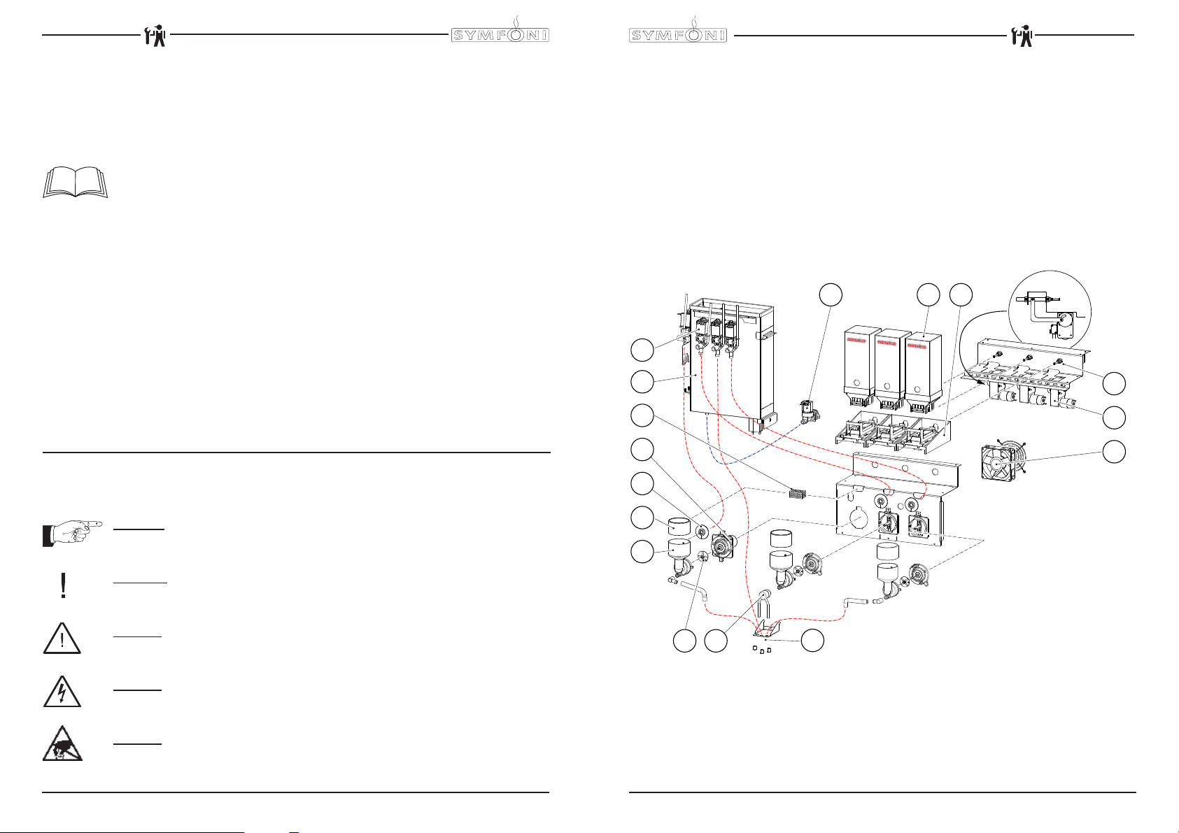
1. BASIC FUNCTIONING
1 Drink outlet/ Hot water outlet 9 Water reservoir
2 Coffee splitter 10 Dispensing valves
3 Mixer impellor 11 Inlet valve
4 Mixer housing 12 Ingredient cartridge
5 Evaporation extractor ring 13 Cartridge holder
6 Hot water connection mixer 14 Push rod
7 Mixer motor 15 Ingredient motor
8 Filter 16 Ventilator
11 12 13
10
Chocolate
Coee
Topping
9
Milk
8
7
14
15
16
Pictograms and symbols.
CAUTION
General indication for: IMPORTANT, CAUTION or REMARK.
WARNING
Warning for possible damage to the device, surroundings or environment.
DANGER
Danger of possible severe damage to the device or physical injury.
DANGER
Danger of electricity and voltage.
DANGER
Danger of electrostatic discharge (ESD) in electronics.
S1000 / S3000 / S3000 MAXI
44
08/2009 Rev. 0.4
6
5
4
08/2009 Rev. 0.4
Fig. 1
23
1
45
S1000 / S3000 / S3000 MAXI
Page 4

S1000 All in One
S3000 All in One (MAXI)
S1000 All in One
S3000 All in One (MAXI)
1.1 Boiler System
Turn on the device using the ON/OFF switch. The display will light up.
The magnetic valve (fi g. 1-11) will open and the hot water reservoir (fi g. 1-9) will be fi lled to the maxi-
mum electrode. The heating element will be switched on. The display shows [ boiler fi lling ] and
[ boiler heating ]. As soon as the NTC sensor measures the set temperature, the heating element will
be switched off.
When a drink is being dispensed the water level drops and the maximum electrode is released;
the inlet valve (2.5 litres/min.) opens and immediately refi lls the reservoir until the maximum level
is reached again. If the water level falls under the minimum electrode level during operation, the
operating panel display will show [refi lling boiler]. If the supply of water is not restored within 90
seconds, the display will show the error message [ E3 level error ] and shut off the inlet valve.
1.2 Temperature regulation
The heating element is turned on when the water temperature falls below the temperature setting and
the minimum electrode registers water. The temperature in the water reservoir is measured using an
NTC precision sensor mounted on the outside wall of the reservoir.
The water temperature also drops when drinks are dispensed. To avoid the temperature regulator from
responding too late, the heating element is switched on as soon as the inlet valve (fi g. 1-11) opens
and cold water is added. The heating element switches off again as soon as the inlet valve shuts
off. The software can also be used to delay when the heating element switches off. See menu item
2.4 Settings / Temperature in the service menu. The heating element always switches off when the
maximum boiler temperature of 97˚C is reached.
1.3 Hot water dispensing
When dispensing drinks one of the dispensing valve (fi g. 1-10) opens and hot water fl ows to the brew-
er or mixer system. The fl ow velocity for each valve is set using the adjustment screw on the valve.
The amount of outfl ow is determined by the length of time that the valve stays open. In order to rinse
the brewer unit and mixer system, a small amount of rinsing water is released shortly after dispensing
to rinse away any ingredient residue.
1.5 Evaporation extractor system
Evaporation released during mixing is largely absorbed by the evaporation extractor ring (fi g. 1-5) and
sucked into the machine via the fi lter (fi g. 1-8). The evaporation and ingredient residue are absorbed
by the fi lter. The fi lter (fi g. 1-8) can be easily reached (for cleaning purposes) by dismantling the mixer
unit (fi g. 1-4). To a large extent, this prevents evaporation from entering the canister outlet and making
ingredients damp.
1.5 Ingredients and mixer system
The ingredients cartridges (fi g. 1-12) are fi tted in a holder (fi g. 1-13). The ingredient slide inside the
holder is driven via a special mechanism by a gear motor (fi g. 1-15). The instant product (ingredient)
is dispensed by a drawer in the bottom of the cartridge and directly dispensed into the mixer unit (fi g.
1-15). At the same time, the dispensing valves (fi g. 1-10) dispense hot water into the mixer unit. The
mixer motor (fi g. 1-7) blends the instant product with water at a speed of 10,700 RPM using the mixer
rotor (fi g. 1-3). The drink fl ows into the cup via the drink outlet (fi g. 1-1). All individual parts mentioned
in this section can be sequentially coordinated using adjustable
parameters (timers) in the control unit.
1.6 Coffee Splitter
The coffee splitter (fi g. 1-2) is specially designed for dispensing two cups of coffee at the Same time.
The build-in fi lter creates the perfect creme layer on top of the coffee.
1.7 Solid State Relay (SSR)
The heating element is controlled by a solid state
relay (fi g. 2C), which supersedes the magnetic
switch that was formerly used for this purpose.
1.8 Steam thermostat
The solid state relay (fi g. 2C) is secured by a steam
thermostat (fi g. 2D) which is build in line with the
overfl ow tube (fi g. 2A). The steam thermostat
contact is in series with the solid state. This thermostat prevents the boiler from boiling empty when
the solid state breaks down in a operating condition.
The thermostat switches the heating element OFF
(fi g. 2B) when steam escapes from the boiler. The
A
B
C
D
SSR
N
L1
C
24Vdc
SSR
D
B
thermostat must be manually reset.
* Modifi ed in the Symfoni models from machine
number 1S06945 (March 2009)
Fig. 2
1.9 Adjustment
1.9.1 Cup volume
First of all we would like to remind you that the cup volume (ml) can easily be set in the service menu
2.1 Quick recipe (page 49 of this document).
The operator of the device (end user) also has access to this quick recipe, which is found under
section 1.4 Quick recipe (see user manual).
As supplier of the device, you can remove the quick recipe from the operator menu if desired. Go to
2.4 Settings / 2.4.9 I/0 Quick recipe via the service menu and change Yes into No.
1.9.2 Drink strength
The amount of product dispensed, and therefore the strength of the drink, is determined by the
number of the times (shots) the cartridge drawer is opened whilst the drink is being made, and how
far the drawer opens each time.
Fig. 3
A. Cartridge holder
B. Ingredient slide
B
C. Push rod
D. Lock nuts
E. Adjustment screw
A
To Fine adjust the ingredient pull please follow below written instructions:
1. Remove the relevant cartridge holder (fi g. 3A).
2. Loosen the adjustment screw lock nuts (fi g. 3D).
3. Adjust the screw (fi g. 3E) as required. Anti-clockwise increases the strength and clockwise
decreases the strength.
4. Replace the cartridge holder and cartridge.
5. Taste the drink and re-adjust as necessary.
6. When the adjustment is correct tighten both the lock nuts (fi g. 3D) against the push rod (fi g. 3C).
7. Replace the cartridge holder and cartridge. Important: After replacing check that the push rod is
free To move back and forwards pushing the slide out as it moves forwards.
+
-
C
D
E
Fig. 3
S1000 / S3000 / S3000 MAXI
46
08/2009 Rev. 0.4
08/2009 Rev. 0.4
47
S1000 / S3000 / S3000 MAXI
Page 5
S1000 All in One
S3000 All in One (MAXI)
S1000 All in One
S3000 All in One (MAXI)
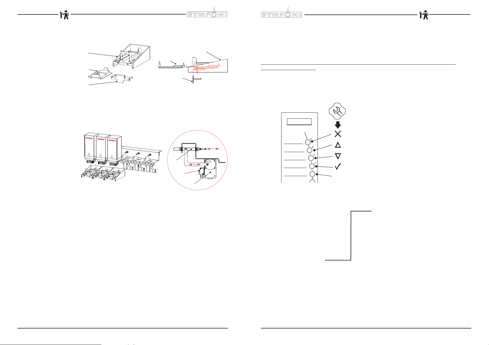
Check also if the mechanism is assembled as shown below.
Fig. 4
A. Cartridge holder
B. Ingredient slide
C. Ingredient shield
a
b
a
b
c
c
1.7.3 Number of shots
If a greater adjustment is needed, the number of times the cartridges drawer is opened For each drink
can be changed.
Fig. 5
A. Ingredient motor
B. Micro switch
C. Push rod
Chocolate
Coee
Topping
Milk
Fig. 4
C
B
A
Fig. 5
The push rod (fi g. 5C) is driven by the ingredient motor (fi g. 5A). Every rotation is being detected by a
micro switch (fi g. 5C). One rotation is one shot.
To set the shot amount go to the service menu 2.3 Recipe setting (page 50 of this document).
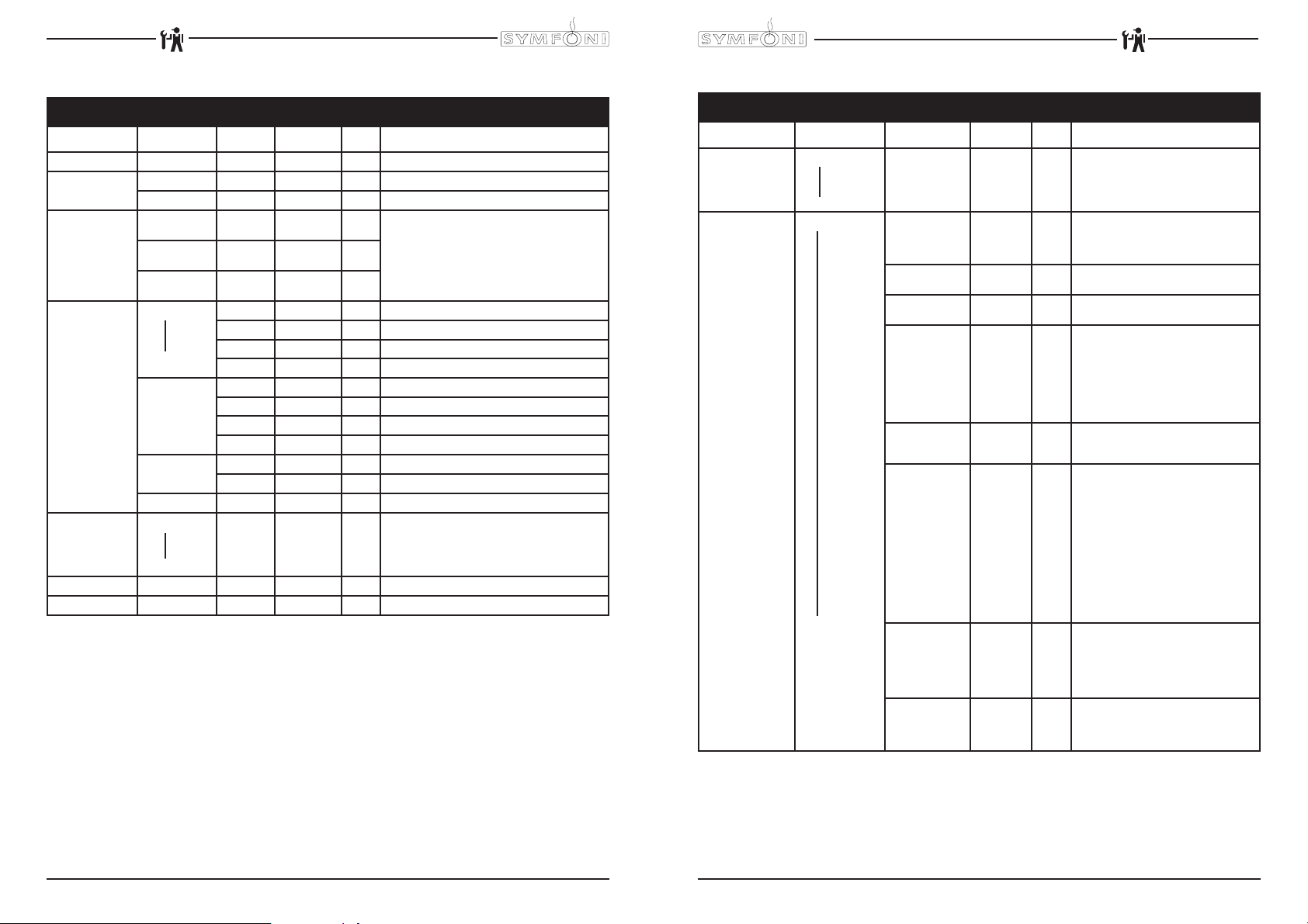
2. MENU STRUCTURE
2.1 The operator/service menu
The majority of settings, including product settings, are protected by a PIN code. This PIN code
ensures that users do not gain access to the service menu.
It is recommended not to leave this document with the user after installation and to change the
standard factory PIN code.
This section describes how the various settings can be changed by trained, authorized service staff.
You can read about how to gain access to the service menu below. On access to the service menu
the control panel has the following functions:
Escape (back without confi rming any changes)
Previous (menu item / increase value)
Next (menu item / decrease value)
Enter (confi rm menu choice)
TEST
Test (press for 1 sec.)
Summary:
Operator menu Service menu
1.0 Free dispensing 2.1 Quick recipe
1.1 Clock 2.2 Button settings
1.2 Timer settings 2.3 Recipe settings
1.3 Recipe counters 2.4 Settings
1.4 Quick recipe 2.5 Reset counters
1.6 Software 2.6 Descale / fi lter
1.7 PIN-code 2.7 Hardware test
2.8 Read log
2.9 Clear log
2.10 Load defaults
2.11 SD menu
2.12 Change PIN code
2.13 Additional settings
S1000 / S3000 / S3000 MAXI
48
08/2009 Rev. 0.4
08/2009 Rev. 0.4
49
S1000 / S3000 / S3000 MAXI
Page 6
S1000 All in One
S3000 All in One (MAXI)
S1000 All in One
S3000 All in One (MAXI)
2.2 The operator menu
Operator menu
Main item Sub item Item Range Set Description
1.0 Free dispensing
1.1 Clock Time HH:MM Set the clock to the correct local time here.
Date DD-MM-JJJJ Set the clock to the correct local time here.
1.2 Timer Mon-Fri On 00:00
Sat On 00:00
Sun On 00:00
1.3 Recipe counters
1.4 Quick recipe Recipe name 1
1.6 Software Software version is readable here.
1.7 PIN-code 2-2-2-2-2 PIN code = press the number 2 key fi ve times.
Recipe 1
Recipe 10
Recipes total Total Cups Total counter for all dispensed recipes
Rinse counters Brewer Number of brewer rinses
Reset counters Total rest of all counters
Recipe name 10
Total Off 00:00 Total counter for recipe 1 (free-paid-jugs)
Free Cups Number of free dispensed drinks (recipe 1)
Paid Cups Number of paid dispensed drinks (recipe 1)
Jug Cups Number of dispensed jugs (recipe 1)
Free Cups Total counter for all free dispensed recipes
Paid Cups Total counter for all paid dispensed recipes
Jug Cups Total counter for all dispensed jugs
Mixer(s) Number of mixer rinses
Cup volume
Yes/no Yes Set the device to free or paid dispensing here.
Off 00:00
Off 00:00
Off 00:00
50-300 ml 125ml Use this for setting the volume easily per recipe
Set the time when the device should operate here. If
the timer switches off the device it will automatically
revert to standby mode.
(drink button).
2.3 The service menu
Service menu
Main item Sub item Item Range Set Description
2.1 Quick recipe Recipe name 1
Recipe name 10
2.2 Button setting Button 1
Button 10
Cup volume
<Recipe name> Recipe list
Recipe active Yes/no Yes Use this to place the product concerned
Price 0,05-2,00 0,10 For paid dispensing a price can be set
Cup volume 50-300ml * 125ml Set the desired cup volume here. All other
Multicup 0-20 0 Set the number of cups that should be
Key switch 0-1-2-3 0 / 1 Recipe button concerned works as follows:
Push & Hold Yes-No No If set to yes: pressing this button starts the
Drip time 0-10 sec. 2 sec. The length of time that the product
50-300 ml 125ml Use this for setting the volume per recipe
See section
3.2
(drink key).
Change any recipe buttons here that
standard factory settings. All settings
that correspond to selected recipes are
automatically loaded.
out of service.
here for each product button.
parameters (e.g. coffee dosage) can be
adjusted automatically. This parameter is
coupled to the quick recipe cup volume!
Advice: deactivate Quick recipe in the
Operator menu; 2.4 Settings / I/O Quick
recipe.
dispensed when the key switch is in the
jug setting.
0= key switch setting n/a
CUP (paid) or JUG* (paid)
1= key switch |: CUP (paid)
key switch –: JUG* (paid)
2= key switch |: no dispensing
key switch –: JUG* (paid)
3= key switch |: CUP (paid)
key switch –: JUG* (free)
(*when multicup is set to >1)
hot/cold water dispensing and releasing it
stops the hot water dispensing.
Only use this option for Water 4 and Water
6 in combination with a hot/cold water
recipe button.
continues to run from the brewer or mixer.
After this time has elapsed a new drink
selection can be made.
S1000 / S3000 / S3000 MAXI
50
08/2009 Rev. 0.4
08/2009 Rev. 0.4
51
S1000 / S3000 / S3000 MAXI
Page 7
S1000 All in One
S3000 All in One (MAXI)
S1000 All in One
S3000 All in One (MAXI)
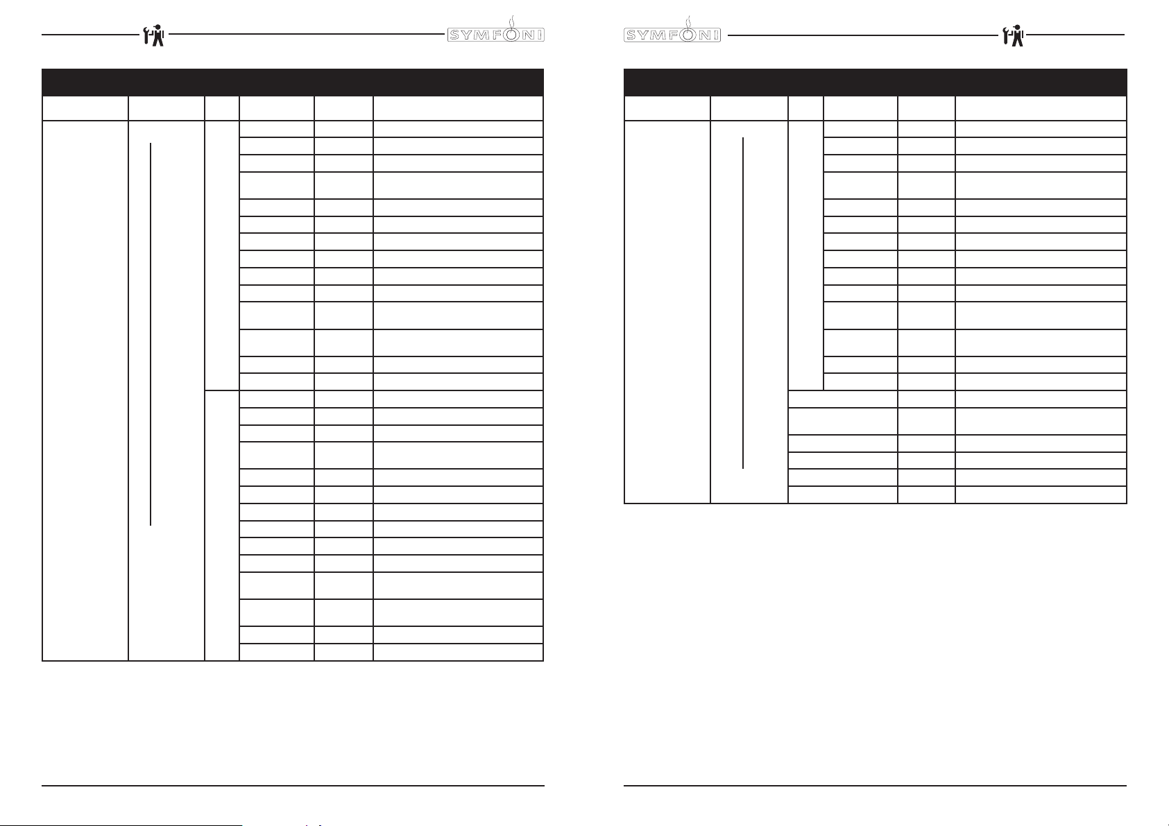
Service menu continued ….
Main item Sub item Sub Item Range Description
2.3 Recipe setting Recipe name 1
Recipe name 10
Unit 1 DV 1 WT 0,0-30,0 s Waiting time Water 1
DV 1 0,0-100,0 ml Dispensing amount Water 1 (Brewer)
Rinse 1 WT 0,0-20,0 s Waiting time Rinsing Water 1
Rinse 1 0,0-15,0 ml
Ingredient 1 WT 0,0-30,0 s Waiting time Cacao (left cartridge)
Ingredient 1 0 - 6 x Number of shots Cacao (left cartridge)
Ingredient 2 WT 0,0-30,0 s Not used
Ingredient 2 0 - 6 x Not used
Mixer 1 WT 0,0-30,0 s Waiting time Mixer 1
Mixer 1 0,0-50,0 s Mixing time Mixer 1
Pause open IM1 0,0-10,0 s
Pause rest IM1 0,0-10,0 s
S3000 (MAXI) Cacao unit /
S1000 coffee unit
Pause open IM2 0,0-10,0 s Not used
Pause rest IM2 0,0-10,0 s Not used
Unit 2 DV 2 WT 0,0-30,0 s Waiting time Water 2
DV 2 0,0-100,0 ml Dispensing amount Water 2
Rinse 2 WT 0,0-20,0 s Waiting time Rinsing Water 2
Rinse 2 0,0-15,0 ml
Coffee WT 0,0-30,0 s Waiting time Coffee (middle cartridge)
Coffee 0 - 6 x Number of shots Coffee (middle cartridge)
Ingredient 4 WT 0,0-30,0 s Not used
Ingredient 4 0 - 6 x Not used
Coffee unit
Mixer 2 WT 0,0-30,0 s Waiting time Mixer 2
Mixer 2 0,0-50,0 s Mixing time Mixer 2
Pause open IM3 0,0-10,0 s
Pause rest IM3 0,0-10,0 s
Pause open IM4 0,0-10,0 s Not used
Pause rest IM4 0,0-10,0 s Not used
Dispensing amount Rinsing Water 1 Automatically deducted from Water 1
Pause time IM 1 when dosing slide is
totally open.
Pause time IM 1 in between 2 shots (motor
pauses in home position)
Dispensing amount Rinsing Water 2 Automatically deducted from Water 2
Pause time IM 3 when dosing slide is
totally open.
Pause time IM 3 in between 2 shots (motor
pauses in home position)
Service menu continued ….
Main item Sub item Sub Item Range Description
2.3 Recipe setting
(continued…)
Recipe name 1
Recipe name 10
Unit 3 DV 3 WT 0,0-30,0 s Waiting time Water 3
DV 3 0-100 ml Dispensing amount Water 3
Rinse 3 WT 0,0-20,0 s Waiting time Rinsing Water 3
Rinse 3 0,0-15,0 ml
Topping WT 0,0-30,0 s Waiting time Topping (right cartridge)
Topping 0 - 6 x Number of shots Topping (right cartridge)
Ingredient 6 WT 0,0-30,0 s Not used
Ingredient 6 0 - 6 x Not used
Mixer 3 WT 0,0-30,0 s Waiting time Mixer 3
Mixer 3 0,0-50,0 s Mixing time Mixer 3
Topping unit
Pause open IM5 0,0-10,0 s
Pause rest IM5 0,0-10,0 s
Pause open IM6 0,0-10,0 s Not used
Pause rest IM6 0,0-10,0 s Not used
DV 4 WT 0,0-30,0 s Waiting time Water 4
DV 4
DV 5 WT 0,0-30,0 s Not used
DV 5 0,0-100,0 ml Not used
DV 6 WT 0,0-30,0 s Not used
DV 6 0,0-100,0 ml Not used
0,0-100,0 ml
Dispensing time Rinsing Water 3
Automatically deducted from Water 3
Pause time IM 5 when dosing slide is
totally open.
Pause time IM 5 in between 2 shots (motor
pauses in home position)
Dispensing amount Water 4
(Hot water dispensed)
S1000 / S3000 / S3000 MAXI
52
08/2009 Rev. 0.4
08/2009 Rev. 0.4
53
S1000 / S3000 / S3000 MAXI
Page 8

S1000 All in One
S3000 All in One (MAXI)
S1000 All in One
S3000 All in One (MAXI)
Service menu continued…
Main item Sub item Item Range
2.4 Settings Language English Language choice display.
Dutch
German
French
Temperature Temp. boiler 70-95°C 95°C Boiler temperature
Hysteresis 2-10°C 2°C
Output block 70-90°C 78°C
Output release 70-90°C 85°C
Stand-by 60-80°C 60°C Boiler temperature during stand-by
Extended Heating 0-5 sec 1 sec
Display Show clock Yes/no No Show clock in display
Show date Yes/no No Show date in display
Message text Yes/no No
Use bleeper Yes/no Yes Sound signal on or off
Fan time 0-300 sec. 60 s.
Fan speed 1 40-100% 60% Fan speed when resting
Fan speed 2 40-100% 100% Fan speed during dispensing
Set-
Description
ting
Ex factory setting English.
Temperature drop, after which boiler
must reheat
Boiler temperature disables dispensing. Display: [Out of order, boiler
heating]
Boiler temperature allows
dispensing again
To maintain the optimum boiler temperature the heating element and
inlet valve switch on simultaneously.
Set the waste delay of the element
here after the inlet valve is closed.
Inlet valve
Heating
Inlet valve
Heating
Show message text (running text) in
display. Only shown if Display Date,
Clock or both are set to no. Message text only programmable using
a future PC programme.
Duration of Fan speed 1 after
dispensing
Service menu continued …..
Main item Sub item Item Range
2.4 Settings
(continued…)
2.5 Reset counters Rinse counters Brewer counter? Reset brewer spoelteller
2.6 Descale/fi lter Service moment 0-50000 12500 After the Service Due setting has
Coin system G13
I/0 Reset counter
I/0 Quick recipe
Drip tray sign.
Recipe counters Recipe counter 1
Reset all counters Reset alle tellers ineens
Service counter ????? The number of beverages dis-
Reset serv. coun After periodic maintenance has
Coin channel 1
0-100,00 +
Token
Coin channel 6
Single vend ja-nee ja
Max coin accep.
Point position 0-2 2 Decimal position in amount
Show credit Yes/no Yes Show credit on the display
MDB No MDB software available yet
Mixer counter? Reset mixer spoelteller
Recipe counter 10
Reset counter total Reset totaal tellers
€ 0,05100,00
Yes/no No
Yes/no Yes
Yes/no Yes Turns off drip tray sensor software.
Set-
Description
ting
€ 0,05
Coin value setting for each channel.
€ 0,10
€0.05-€2 respectively.
€ 0,20
0.00=free
€ 0,50
TOKEN=coffee token
€ 1,00
€ 2,00
Yes: any excess credit is not
retained for next drink. No: credit
retained for next drink.
Coins larger than € 1.00 are rejected
and ejected through the return slot
€ 1,00
of the coin mechanism. Adjust to the
highest recipe product price.
Add Reset counters menu item to
the operator menu
Add Quick recipe menu item to the
operator menu
Reset recepttellers per recept.
been reached the Descale/fi lter
indicator will be displayed. See sec-
tion 5. Service
pensed is counted here. Check here
to see how far the machine is from
periodic maintenance (descaling
boiler or replacing water fi lter).
been carried out (boiler descaled or
fi lter replaced) the service counter
should be set to nil.
S1000 / S3000 / S3000 MAXI
54
08/2009 Rev. 0.4
08/2009 Rev. 0.4
55
S1000 / S3000 / S3000 MAXI
Page 9

S1000 All in One
S3000 All in One (MAXI)
S1000 All in One
S3000 All in One (MAXI)
Service menu continued….
Main item Sub item Sub Range Description
2.7 Hardware test Inputs Temperature Boiler temp
Outputs
Test by holding
in recipe button 5.
# During test the
display shows
the Nominal
current (mA)
When the
Nominal current
of a output rises
above the set
current *
mentioned output
will be shut off.
Calib. valves
Test by holding
in recipe button
5 (for 1 sec.)
to open the relevant valve for
10 seconds.
Level sensors High Yes/no
Drip tray sensor Yes/no
Shot 1 Yes/no
Shot 2 Yes/no
Shot 3 Yes/no
Key switch Yes/no
KW1
DV1 Dispenser valve 1 (Mixer 1)
DV2 Dispenser valve 2 (Mixer 2)
DV3 Dispenser valve 3 (Mixer 3)
DV4 Dispenser valve 4 (Hot water)
DV5 Not used
DV6 Not used
IM1 #
IM2 # Not used
IM3 # Ingredients motor 3 (Coffee cartridge)
IM4 # Not used
IM5 # Ingredients motor 5 (Topping cartridge)
IM6 # Not used
MM1 #
MM2 # Mixer motor 2
MM3 # Mixer motor 3
Ventilator * 200 mA Ventilator
LED’s Not used
DV1 15 ml / sec Calibrate to 150 ml (10 sec x 15 ml)
DV2 15 ml / sec Calibrate to 150 ml (10 sec x 15 ml)
DV3 15 ml / sec Calibrate to 150 ml (10 sec x 15 ml)
DV4 20 ml / sec Calibrate to 200 ml (10 sec x 20 ml)
DV5 Not used
DV6 Not used
Low Yes/no
* 400 mA
* 400 mA
* 800 mA
Shows the status of the sensors/switches
indicated
Inlet valve (Boiler)
Ingredients motor 1 (Cacao cartridge)
Mixer motor 1
Service menu continued….
Main item Sub item Item Description
2.8 Read log Saves last 20 error messages, including date and time
2.9 Clear log Are you sure? Clears log
Are you sure?
2.10 Load defaults
* From software
V3.08 sept 2009
2.11 SD menu
Before saving
or loading data,
insert an empty SD
memory card into
the card reader .
This is located
behind the stainless
steel panel on the
inside of the door.
SD card
specifi cations:
- 16MB or greater
- FAT16 format
2.12 Change PIN New PIN code Repeat PIN code This menu item is for changing the PIN code using buttons 1-4 only.
Model #
S3000
S3000 MAXI
S1000 *
S1000 *
S1000 *
Load data Pers. settings
Memory Card
Save data Pers. settings
Memory Card
Type code
SY1A xx
SY2A xx
SY3A xx
SY4A xx
SY5A xx
Language
Recipe
Recipes
When a new circuit board is introduced it is necessary to load defaults. When loading defaults it must be stated on the Symfoni model
plate. The correct model settings are not loaded until the question
‘Are you sure?’ has been confi rmed.
Attention:
● Before you start changing the button- and/or receipt- settings, first
close the service menu, only after re-entering the service menu the
new model settings will be activated.
● When you confi rm this setting all loaded factory settings and
changed programmed values will be lost.
● After loading defaults the PIN code reverts to 2-2-2-2-2 and the
language reverts to English. Change if necessary.
This menu item is for loading personal settings to the device using
an SD memory card. This fi le contains the (amended) personal set-
tings for menus: 2.4 Settings / 2/6 Descale-fi lter / 2.13 Additional
settings. The data fi le (Ofxxxx00.mdu) should be on the SD card.
This menu item is for loading a different language set to the
device. The data fi le (xxxxxx.tlf) should be on the SD card.
This menu item is for loading personal recipes to the device using
an SD memory card. This fi le contains the (amended) personal reci-
pes for menus: 2.1 Quick recipe / 2.2 Button settings / 2.3 Recipe
settings. The data fi le (OFxxxx00.rcu) should be on the SD card.
This menu item is for saving personal settings to an SD memory
card and copying them to another device.
All settings amended in menus: 2.4 Settings / 2.6 Descale-fi lter /
2.13 Additional settings are loaded to the SD card in one data fi le
(OFxxxx00.mdu).
This menu item is for saving personal recipes to an SD memory
card and copying them to another device.
All settings amended in menus: 2.1 Quick recipe / 2.2 Button
settings/ 2.3 Recipe settings are loaded to the SD card in one data
fi le (OFxxxx00.rcu).
The entire service menu is accessed with this PIN code, which
prevents unintentional changes from being made to the machine
settings by untrained staff.
• The ex-factory PIN code is 2-2-2-2-2
PIN code forgotten or needs to be deactivated?
The PIN code input display (operator menu item 1.7) shows a
number on the right. Enter the corresponding PIN code (see list on
p.56) to access the service menu.
S1000 / S3000 / S3000 MAXI
56
08/2009 Rev. 0.4
08/2009 Rev. 0.4
57
S1000 / S3000 / S3000 MAXI
Page 10

S1000 All in One
S3000 All in One (MAXI)
S1000 All in One
S3000 All in One (MAXI)
PIN Code Table
Table 1
Water Hardness Table
No. Pincode No. Pincode
1 34242 11 13332
2 31434 12 12413
3 41343 13 43121
4 43232 14 11142
5 23341 15 21211
6 42131 16 12233
7 24244 17 34144
8 23241 18 41433
9 24323 19 31241
10 31332 20 22324
Water
Quality
°D °F mmol/l mgCaCo3/l
Hardness Limescale
Very hard 18-30 32-55 3,2-5,3 321- 536 5000
Hard 12-18 22-32 2,2-3,2 214-321 8500
Average 8-12 15-22 1,4-2,2 268-214 12.500*
Soft 4-8 7-15 0,7-1,4 72-268 20.500
Table 2
Very soft 0-4 0-7 0- 0,7 0-72 0 = off
3. RECIPE SETTINGS
3.1 Cartridge confi guration
The Symfoni models have the following standard cartridge confi gurations (fi g. 6):
Chocolate
Coee
Symfoni S1000 [ Coffee ]
Symfoni S3000 [ Cacao / Coffee / Topping ]
Symfoni S3000 MAXI [ Cacao / Coffee / Topping ]
Coee
Topping
Milk
Fig. 6
Indicator ...cups
3.2 Button settings
The standard of programmed recipes (table 3) can easily be transferred over the 10 recipe buttons.
See service menu 2.2 Button settings (page 49).
The optional recipes table are already contained in the software and can easily be programmed under
one recipe button. See service menu 2.2 Button settings (page 49).
Table 3
S3000 S3000 MAXI S1000
Coffee
S1000
Choco
S1000
Milk
Model 1A Model 2A Model 3A Model 4A Model 5A
1 Cacao Cacao Coffee Cacao Topping
2 Coffee Coffee - - -
3 Topping Topping - - -
Unit 2 Unit 3
Unit 1
Cartridge
135
Coee
Cacao
DV 1
Button
1
2
3
4
5
6
7
8
Standard recipes
9
10
Coffee Coffee Coffee
Coffee Coffee Coffee
Espresso Espresso Espresso Hot water -
Coffee Milk Coffee Milk Hot water - Hot Chocolate Hot Chocolate - - Chocolate Milk Chocolate Milk
Cappuccino Cappuccino
Moccacino Moccacino
Espresso Choc Jug of Coffee
Hot water Hot water
Jug of Coffee Espresso Choc Jug of Coffee Jug of Hot Water Jug of Hot Water
Jug of Hot Water Jug of Hot Water Jug of Hot Water
Latte Macchiato Latte Macchiato Decaf
Hot Milk Hot Milk
Decaf Decaf
Topping
DV 2 DV 3
Unit 2 Unit 3
Unit 1
135
Cacao
Topping
Coee
DV 2 DV 3
DV 1
Unit 1
Unit 1
1
Coee
DV 1
1
Coee
DV 1
Hot Chocolate small
Hot Chocolate large
Unit 1
1
Coee
DV 1
Hot Milk
Hot water
Optional recipes
* = only if the necessary ingredient (s) are
available in the catridges
S1000 / S3000 / S3000 MAXI
58
08/2009 Rev. 0.4
08/2009 Rev. 0.4
59
S1000 / S3000 / S3000 MAXI
Page 11

S1000 All in One
S3000 All in One (MAXI)
S1000 All in One
S3000 All in One (MAXI)
3.3.1 Parameter settings S3000
SY1abb00.RCD Buttons Optional recipe
12345678910 1112131415
Symfoni 1A
Standard
Coffee
Double Coffee
Espresso
Coffee Milk
Chocolate
Chocolate Milk
Cappuccino
Moccacino
Espresso Choc
Hot Water
Jug Coffee
Jug Hot Water
Latte Macchiato
Recipe 1 22 527179101511 2021131838
Recipe Active 1111111111 1 1 111
Brewer 0000000000 0 0 00 0
Price 0,10 0,10 0,10 0,10 0,10 0,10 0,10 0,10 0,10 0,10 0,10 0,10 0,10 0,10 0,10
Cup volume ml 125 250 70 125 125 125 150 120 125 125 125 125 150 125 125
Multicup 0000000000 1212000
Key switch 3333333333 0 0 333
Push & Hold 0000000000 0 00 00
Leak out time sec. 2,0 2,0 2,0 2,0 2,0 2,0 2,0 2,0 2,0 2,0 2,0 2,0 2,0 2,0 2,0
DV 1 WT sec. 0,0 0,0 0,0 0,0 0,0 0,0 0,0 4,0 0,0 0,0 0,0 0,0 0,0 0,0 0,0
DV 1 ml 0,0 0,0 0,0 0,0 100,0 66,0 0,0 30,0 66,0 0,0 0,0 0,0 0,0 0,0 0,0
Rinse 1 WT sec. 0,0 0,0 0,0 0,0 0,5 0,5 0,0 0,5 0,5 0,0 0,0 0,0 0,0 0,0 0,0
Rinse 1 ml 0,0 0,0 0,0 0,0 7,5 7,5 0,0 7,5 7,5 0,0 0,0 0,0 0,0 0,0 0,0
Cacao 1 WT sec. 0,0 0,0 0,0 0,0 0,5 0,5 0,0 0,5 0,5 0,0 0,0 0,0 0,0 0,0 0,0
Cacao 1 Shots 0000330130 0 0 0 0 0
Ingredient 2 WT sec. 0,0 0,0 0,0 0,0 0,0 0,0 0,0 0,0 0,0 0,0 0,0 0,0 0,0 0,0 0,0
Ingredient 2 Shots 0000000000 0 0 0 00
Mixer 1 WT sec. 0,0 0,0 0,0 0,0 0,5 0,5 0,0 0,5 0,5 0,0 0,0 0,0 0,0 0,0 0,0
Mixer 1 sec. 0,0 0,0 0,0 0,0 7,1 4,9 0,0 2,5 4,9 0,0 0,0 0,0 0,0 0,0 0,0
DV 2 WT sec. 0,0 0,0 0,0 0,0 0,0 0,0 9,0 2,0 6,0 0,0 0,0 0,0 20,0 0,0 0,0
DV 2 ml 100,0 100,0 100,0 66,0 0,0 0,0 34,0 30,0 34,0 0,0 100,0 0,0 34,0 0,0 0,0
Rinse 2 WT sec. 0,5 0,5 0,5 0,5 0,0 0,0 0,5 1,0 0,5 0,0 0,5 0,0 0,5 0,0 0,0
Rinse 2 ml 7,5 7,5 7,5 7,5 0,0 0,0 7,5 7,5 7,5 0,0 7,5 0,0 7,5 0,0 0,0
Coffee 3 WT sec. 0,5 0,5 0,5 0,5 0,0 0,0 0,5 0,0 0,5 0,0 0,5 0,0 0,5 0,0 0,0
Coffee 3 Shots 2422002210 2 0 2 00
Ingredient 4 WT sec. 0,0 0,0 0,0 0,0 0,0 0,0 0,0 0,0 0,0 0,0 0,0 0,0 0,0 0,0 0,0
Ingredient 4 Shots 0000000000 0 0 0 00
Mixer 2 WT sec. 0,5 0,5 0,5 0,5 0,0 0,0 0,5 0,5 0,5 0,0 0,5 0,0 0,5 0,0 0,0
Mixer 2 sec. 7,1 7,1 6,1 4,9 0,0 0,0 3,0 3,0 2,7 0,0 7,1 0,0 2,7 0,0 0,0
DV 3 WT sec. 0,0 0,0 0,0 5,0 0,0 6,0 0,0 0,0 0,0 0,0 0,0 0,0 0,0 0,0 0,0
DV 3 ml 0,0 0,0 0,0 34,0 0,0 34,0 66,0 40,0 0,0 0,0 0,0 0,0 66,0 100,0 100,0
Rinse 3 WT sec. 0,0 0,0 0,0 0,5 0,0 0,5 0,5 0,5 0,0 0,0 0,0 0,0 0,5 0,5 0,5
Rinse 3 ml 0,0 0,0 0,0 7,5 0,0 7,5 7,5 7,5 0,0 0,0 0,0 0,0 7,5 7,5 7,5
Topping 5 WT sec. 0,0 0,0 0,0 0,5 0,0 0,5 0,5 0,5 0,0 0,0 0,0 0,0 0,5 0,5 0,5
Topping 5 Shots 0001013200 0 03 32
Ingredient 6 WT sec. 0,0 0,0 0,0 0,0 0,0 0,0 0,0 0,0 0,0 0,0 0,0 0,0 0,0 0,0 0,0
Ingredient 6 Shots 0000000000 0 0 0 00
Mixer 3 WT sec. 0,0 0,0 0,0 0,5 0,0 0,5 0,5 0,5 0,0 0,0 0,0 0,0 0,5 0,5 0,5
Mixer 3 sec. 0,0 0,0 0,0 2,7 0,0 2,7 4,9 3,1 0,0 0,0 0,0 0,0 4,9 7,1 7,1
DV 4 WT sec. 0,0 0,0 0,0 0,0 0,0 0,0 0,0 0,0 0,0 0,0 0,0 0,0 0,0 0,0 0,0
DV 4 ml 0,0 0,0 0,0 0,0 0,0 0,0 0,0 0,0 0,0 100,0 0,0 100,0 0,0 0,0 0,0
DV 5 WT sec. 0,0 0,0 0,0 0,0 0,0 0,0 0,0 0,0 0,0 0,0 0,0 0,0 0,0 0,0 0,0
DV 5 ml 0,0 0,0 0,0 0,0 0,0 0,0 0,0 0,0 0,0 0,0 0,0 0,0 0,0 0,0 0,0
DV 6 WT sec. 0,0 0,0 0,0 0,0 0,0 0,0 0,0 0,0 0,0 0,0 0,0 0,0 0,0 0,0 0,0
DV 6 ml 0,0 0,0 0,0 0,0 0,0 0,0 0,0 0,0 0,0 0,0 0,0 0,0 0,0 0,0 0,0
Pause Open IM 1 sec. 0,0 0,0 0,0 0,0 0,0 0,0 0,0 0,0 0,0 0,0 0,0 0,0 0,0 0,0 0,0
Pause Rest IM 1 sec. 0,0 0,0 0,0 0,0 0,0 0,0 0,0 0,0 0,0 0,0 0,0 0,0 0,0 0,0 0,0
Pause Open IM 2 sec. 0,0 0,0 0,0 0,0 0,0 0,0 0,0 0,0 0,0 0,0 0,0 0,0 0,0 0,0 0,0
Pause Rest IM 2 sec. 0,0 0,0 0,0 0,0 0,0 0,0 0,0 0,0 0,0 0,0 0,0 0,0 0,0 0,0 0,0
Pause Open IM 3 sec. 0,0 0,0 0,0 0,0 0,0 0,0 0,0 0,0 0,0 0,0 0,0 0,0 0,0 0,0 0,0
Pause Rest IM 3 sec. 1,0 2,0 0,0 0,0 0,0 0,0 0,0 0,0 0,0 0,0 1,0 0,0 0,0 0,0 0,0
Pause Open IM 4 sec. 0,0 0,0 0,0 0,0 0,0 0,0 0,0 0,0 0,0 0,0 0,0 0,0 0,0 0,0 0,0
Pause Rest IM 4 sec. 0,0 0,0 0,0 0,0 0,0 0,0 0,0 0,0 0,0 0,0 0,0 0,0 0,0 0,0 0,0
Pause Open IM 5 sec. 0,0 0,0 0,0 0,0 0,0 0,0 0,0 0,0 0,0 0,0 0,0 0,0 0,0 0,0 0,0
Pause Rest IM 5 sec. 0,0 0,0 0,0 0,0 0,0 0,0 0,0 0,0 0,0 0,0 0,0 0,0 0,0 0,0 0,0
Pause Open IM 6 sec. 0,0 0,0 0,0 0,0 0,0 0,0 0,0 0,0 0,0 0,0 0,0 0,0 0,0 0,0 0,0
Pause Rest IM 6 sec. 0,0 0,0 0,0 0,0 0,0 0,0 0,0 0,0 0,0 0,0 0,0 0,0 0,0 0,0 0,0
Hot Milk
Decaf
3.3.2 Parameter settings S3000 MAXI
SY2abb00.RCD Buttons Optional recipe
12345678910 1112131415
Symfoni 2A
Standard
Coffee
Double Coffee
Espresso
Coffee Milk
Chocolate
Chocolate Milk
Cappuccino
Moccacino
Jug Coffee
Hot Water
Espresso Choc
Jug Hot Water
Latte Macchiato
Recipe 1 22 5 2 7 17 9 10 20 11 15 21 13 18 38
Recipe Active 1 1 1 1111111 1 1 1 1 1
Brewer 0 0 0 0000000 0 0 0 0 0
Price 0,10 0,10 0,10 0,10 0,10 0,10 0,10 0,10 0,10 0,10 0,10 0,10 0,10 0,10 0,10
Cup volume ml 125 250 70 125 125 125 150 120 125 125 125 125 150 125 125
Multicup 0 0 0 00000120 0 120 0 0
Key switch 3 3 3 3333303 3 0 3 3 3
Push & Hold 0 0 0 0000000 0 0 0 0 0
Leak out time sec. 2,0 2,0 2,0 2,0 2,0 2,0 2,0 2,0 2,0 2,0 2,0 2,0 2,0 2,0 2,0
DV 1 WT sec. 0,0 0,0 0,0 0,0 0,0 0,0 0,0 4,0 0,0 0,0 0,0 0,0 0,0 0,0 0,0
DV 1 ml 0,0 0,0 0,0 0,0 100,0 66,0 0,0 30,0 0,0 0,0 66,0 0,0 0,0 0,0 0,0
Rinse 1 WT sec. 0,0 0,0 0,0 0,0 0,5 0,5 0,0 0,5 0,0 0,0 0,5 0,0 0,0 0,0 0,0
Rinse 1 ml 0,0 0,0 0,0 0,0 7,5 7,5 0,0 7,5 0,0 0,0 7,5 0,0 0,0 0,0 0,0
Cacao 1 WT sec. 0,0 0,0 0,0 0,0 0,5 0,5 0,0 0,5 0,0 0,0 0,5 0,0 0,0 0,0 0,0
Cacao 1 Shots 0 0 0 0330100 3 0 0 0 0
Ingredient 2 WT sec. 0,0 0,0 0,0 0,0 0,0 0,0 0,0 0,0 0,0 0,0 0,0 0,0 0,0 0,0 0,0
Ingredient 2 Shots 0 0 0 0000000 0 0 0 0 0
Mixer 1 WT sec. 0,0 0,0 0,0 0,0 0,5 0,5 0,0 0,5 0,0 0,0 0,5 0,0 0,0 0,0 0,0
Mixer 1 sec. 0,0 0,0 0,0 0,0 7,1 4,9 0,0 2,5 0,0 0,0 4,9 0,0 0,0 0,0 0,0
DV 2 WT sec. 0,0 0,0 0,0 0,0 0,0 0,0 9,0 2,0 0,0 0,0 6,0 0,0 20,0 0,0 0,0
DV 2 ml 100,0 100,0 100,0 66,0 0,0 0,0 34,0 30,0 100,0 0,0 34,0 0,0 34,0 0,0 0,0
Rinse 2 WT sec. 0,5 0,5 0,5 0,5 0,0 0,0 0,5 1,0 0,5 0,0 0,5 0,0 0,5 0,0 0,0
Rinse 2 ml 7,5 7,5 7,5 7,5 0,0 0,0 7,5 7,5 7,5 0,0 7,5 0,0 7,5 0,0 0,0
Coffee 3 WT sec. 0,5 0,5 0,5 0,5 0,0 0,0 0,5 0,0 0,5 0,0 0,5 0,0 0,5 0,0 0,0
Coffee 3 Shots 2 4 2 2002220 1 0 2 0 0
Ingredient 4 WT sec. 0,0 0,0 0,0 0,0 0,0 0,0 0,0 0,0 0,0 0,0 0,0 0,0 0,0 0,0 0,0
Ingredient 4 Shots 0 0 0 0000000 0 0 0 0 0
Mixer 2 WT sec. 0,5 0,5 0,5 0,5 0,0 0,0 0,5 0,5 0,5 0,0 0,5 0,0 0,5 0,0 0,0
Mixer 2 sec. 7,1 7,1 6,1 4,9 0,0 0,0 3,0 3,0 7,1 0,0 2,7 0,0 2,7 0,0 0,0
DV 3 WT sec. 0,0 0,0 0,0 5,0 0,0 6,0 0,0 0,0 0,0 0,0 0,0 0,0 0,0 0,0 0,0
DV 3 ml 0,0 0,0 0,0 34,0 0,0 34,0 66,0 40,0 0,0 0,0 0,0 0,0 66,0 100,0 100,0
Rinse 3 WT sec. 0,0 0,0 0,0 0,5 0,0 0,5 0,5 0,5 0,0 0,0 0,0 0,0 0,5 0,5 0,5
Rinse 3 ml 0,0 0,0 0,0 7,5 0,0 7,5 7,5 7,5 0,0 0,0 0,0 0,0 7,5 7,5 7,5
Topping 5 WT sec. 0,0 0,0 0,0 0,5 0,0 0,5 0,5 0,5 0,0 0,0 0,0 0,0 0,5 0,5 0,5
Topping 5 Shots 0 0 0 1013200 0 0 3 3 2
Ingredient 6 WT sec. 0,0 0,0 0,0 0,0 0,0 0,0 0,0 0,0 0,0 0,0 0,0 0,0 0,0 0,0 0,0
Ingredient 6 Shots 0 0 0 0000000 0 0 0 00
Mixer 3 WT sec. 0,0 0,0 0,0 0,5 0,0 0,5 0,5 0,5 0,0 0,0 0,0 0,0 0,5 0,5 0,5
Mixer 3 sec. 0,0 0,0 0,0 2,7 0,0 2,7 4,9 3,1 0,0 0,0 0,0 0,0 4,9 7,1 7,1
DV 4 WT sec. 0,0 0,0 0,0 0,0 0,0 0,0 0,0 0,0 0,0 0,0 0,0 0,0 0,0 0,0 0,0
DV 4 ml 0,0 0,0 0,0 0,0 0,0 0,0 0,0 0,0 0,0 100,0 0,0 100,0 0,0 0,0 0,0
DV 5 WT sec. 0,0 0,0 0,0 0,0 0,0 0,0 0,0 0,0 0,0 0,0 0,0 0,0 0,0 0,0 0,0
DV 5 ml 0,0 0,0 0,0 0,0 0,0 0,0 0,0 0,0 0,0 0,0 0,0 0,0 0,0 0,0 0,0
DV 6 WT sec. 0,0 0,0 0,0 0,0 0,0 0,0 0,0 0,0 0,0 0,0 0,0 0,0 0,0 0,0 0,0
DV 6 ml 0,0 0,0 0,0 0,0 0,0 0,0 0,0 0,0 0,0 0,0 0,0 0,0 0,0 0,0 0,0
Pause Open IM 1 sec. 0,0 0,0 0,0 0,0 0,0 0,0 0,0 0,0 0,0 0,0 0,0 0,0 0,0 0,0 0,0
Pause Rest IM 1 sec. 0,0 0,0 0,0 0,0 0,0 0,0 0,0 0,0 0,0 0,0 0,0 0,0 0,0 0,0 0,0
Pause Open IM 2 sec. 0,0 0,0 0,0 0,0 0,0 0,0 0,0 0,0 0,0 0,0 0,0 0,0 0,0 0,0 0,0
Pause Rest IM 2 sec. 0,0 0,0 0,0 0,0 0,0 0,0 0,0 0,0 0,0 0,0 0,0 0,0 0,0 0,0 0,0
Pause Open IM 3 sec. 0,0 0,0 0,0 0,0 0,0 0,0 0,0 0,0 0,0 0,0 0,0 0,0 0,0 0,0 0,0
Pause Rest IM 3 sec. 1,0 2,0 0,0 0,0 0,0 0,0 0,0 0,0 1,0 0,0 0,0 0,0 0,0 0,0 0,0
Pause Open IM 4 sec. 0,0 0,0 0,0 0,0 0,0 0,0 0,0 0,0 0,0 0,0 0,0 0,0 0,0 0,0 0,0
Pause Rest IM 4 sec. 0,0 0,0 0,0 0,0 0,0 0,0 0,0 0,0 0,0 0,0 0,0 0,0 0,0 0,0 0,0
Pause Open IM 5 sec. 0,0 0,0 0,0 0,0 0,0 0,0 0,0 0,0 0,0 0,0 0,0 0,0 0,0 0,0 0,0
Pause Rest IM 5 sec. 0,0 0,0 0,0 0,0 0,0 0,0 0,0 0,0 0,0 0,0 0,0 0,0 0,0 0,0 0,0
Pause Open IM 6 sec. 0,0 0,0 0,0 0,0 0,0 0,0 0,0 0,0 0,0 0,0 0,0 0,0 0,0 0,0 0,0
Pause Rest IM 6 sec. 0,0 0,0 0,0 0,0 0,0 0,0 0,0 0,0 0,0 0,0 0,0 0,0 0,0 0,0 0,0
Hot Milk
Decaf
S1000 / S3000 / S3000 MAXI
60
Table 4
08/2009 Rev. 0.4
08/2009 Rev. 0.4
61
Table 5
S1000 / S3000 / S3000 MAXI
Page 12

S1000 All in One
S3000 All in One (MAXI)
3.2.3 Parameter settings S1000 Coffee 3.2.4 Parameter settings S1000 Cacao
S1000 All in One
S3000 All in One (MAXI)
SY3Age00.RCD Buttons Optional recipe
12345 1112131415
Symfoni 3A
Standard
Coffee
Double Coffee
Espresso
Hot Water
Recipe 1 22 5 11 0 20 21 38 0 0
Recipe Active 11110 11100
Brewer 00000 00000
Price 0,10 0,10 0,10 0,10 0,00 0,10 0,10 0,10 0,00 0,00
Cup volume ml 125 250 70 125 0 125 125 125 0 0
Multicup 00000 1212000
Key switch 33330 00300
Push & Hold 00000 00000
Leak out time sec. 2,0 2,0 2,0 2,0 0,0 2,0 2,0 2,0 0,0 0,0
DV 1 WT sec. 0,0 0,0 0,0 0,0 0,0 0,0 0,0 0,0 0,0 0,0
DV 1 ml 100,0 100,0 100,0 0,0 0,0 100,0 0,0 100,0 0,0 0,0
Rinse 1 WT sec. 0,5 0,5 0,5 0,0 0,0 0,5 0,0 0,5 0,0 0,0
Rinse 1 ml 7,5 7,5 7,5 0,0 0,0 7,5 0,0 7,5 0,0 0,0
Ingredient 1 WT sec. 0,5 0,5 0,5 0,0 0,0 0,5 0,0 0,5 0,0 0,0
Ingredient 1 shots 24200 20200
Ingredient 2 WT sec. 0,0 0,0 0,0 0,0 0,0 0,0 0,0 0,0 0,0 0,0
Ingredient 2 shots 00000 00000
Mixer 1 WT sec. 0,5 0,5 0,5 0,0 0,0 0,5 0,0 0,5 0,0 0,0
Mixer 1 sec. 7,1 7,1 6,1 0,0 0,0 7,1 0,0 7,1 0,0 0,0
DV 2 WT sec. 0,0 0,0 0,0 0,0 0,0 0,0 0,0 0,0 0,0 0,0
DV 2 ml 0,0 0,0 0,0 0,0 0,0 0,0 0,0 0,0 0,0 0,0
Rinse 2 WT sec. 0,0 0,0 0,0 0,0 0,0 0,0 0,0 0,0 0,0 0,0
Rinse 2 ml 0,0 0,0 0,0 0,0 0,0 0,0 0,0 0,0 0,0 0,0
Ingredient 3 WT sec. 0,0 0,0 0,0 0,0 0,0 0,0 0,0 0,0 0,0 0,0
Ingredient 3 shots 00000 00000
Ingredient 4 WT sec. 0,0 0,0 0,0 0,0 0,0 0,0 0,0 0,0 0,0 0,0
Ingredient 4 shots 00000 00000
Mixer 2 WT sec. 0,0 0,0 0,0 0,0 0,0 0,0 0,0 0,0 0,0 0,0
Mixer 2 sec. 0,0 0,0 0,0 0,0 0,0 0,0 0,0 0,0 0,0 0,0
DV 3 WT sec. 0,0 0,0 0,0 0,0 0,0 0,0 0,0 0,0 0,0 0,0
DV 3 ml 0,0 0,0 0,0 0,0 0,0 0,0 0,0 0,0 0,0 0,0
Rinse 3 WT sec. 0,0 0,0 0,0 0,0 0,0 0,0 0,0 0,0 0,0 0,0
Rinse 3 ml 0,0 0,0 0,0 0,0 0,0 0,0 0,0 0,0 0,0 0,0
Ingredient 5 WT sec. 0,0 0,0 0,0 0,0 0,0 0,0 0,0 0,0 0,0 0,0
Ingredient 5 shots 00000 00000
Ingredient 6 WT sec. 0,0 0,0 0,0 0,0 0,0 0,0 0,0 0,0 0,0 0,0
Ingredient 6 shots 00000 00000
Mixer 3 WT sec. 0,0 0,0 0,0 0,0 0,0 0,0 0,0 0,0 0,0 0,0
Mixer 3 sec. 0,0 0,0 0,0 0,0 0,0 0,0 0,0 0,0 0,0 0,0
DV 4 WT sec. 0,0 0,0 0,0 0,0 0,0 0,0 0,0 0,0 0,0 0,0
DV 4 ml 0,0 0,0 0,0 100,0 0,0 0,0 100,0 0,0 0,0 0,0
DV 5 WT sec. 0,0 0,0 0,0 0,0 0,0 0,0 0,0 0,0 0,0 0,0
DV 5 ml 0,0 0,0 0,0 0,0 0,0 0,0 0,0 0,0 0,0 0,0
DV 6 WT sec. 0,0 0,0 0,0 0,0 0,0 0,0 0,0 0,0 0,0 0,0
DV 6 ml 0,0 0,0 0,0 0,0 0,0 0,0 0,0 0,0 0,0 0,0
Pause Open IM 1 sec.
Pause Rest IM 1 sec.
Pause Open IM 2 sec.
Pause Rest IM 2 sec.
Pause Open IM 3 sec.
Pause Rest IM 3 sec.
Pause Open IM 4 sec.
Pause Rest IM 4 sec.
Pause Open IM 5 sec.
Pause Rest IM 5 sec.
Pause Open IM 6 sec.
Pause Rest IM 6 sec.
00000 00000
1020000 100000
00000 00000
00000 00000
00000 00000
00000 00000
00000 00000
00000 00000
00000 00000
00000 00000
00000 00000
00000 00000
>none<
Jug Coffee
Jug Hot Water
Decaf
>none<
>none<
Tabel 6
SY4Age00.RCD Buttons Optional recipe
12345 1112131415
Symfoni 4A
Standard
Chocolate
Small
Chocolate
Large
Hot Water
>none<
Recipe 62 63 11 0 0 21 0 0 0 0
Recipe Active 1 1 1 0 0 1 0 0 0 0
Brewer 0 0 0 0 0 0 0 0 0 0
Price 0,10 0,10 0,10 0,00 0,00 0,10 0,00 0,00 0,00 0,00
Cup volume ml 125 200 125 0 0 125 0 0 0 0
Multicup 0 0 0 0 0 12 0 0 0 0
Key switch 3 3 3 0 0 0 0 0 0 0
Push & Hold 0 0 0 0 0 0 0 0 0 0
Leak out time sec. 2,0 2,0 2,0 0,0 0,0 2,0 0,0 0,0 0,0 0,0
DV 1 WT sec. 0,0 0,0 0,0 0,0 0,0 0,0 0,0 0,0 0,0 0,0
DV 1 ml 100,0 100,0 0,0 0,0 0,0 0,0 0,0 0,0 0,0 0,0
Rinse 1 WT sec. 0,5 0,5 0,0 0,0 0,0 0,0 0,0 0,0 0,0 0,0
Rinse 1 ml 7,5 7,5 0,0 0,0 0,0 0,0 0,0 0,0 0,0 0,0
Ingredient 1 WT sec. 0,5 0,5 0,0 0,0 0,0 0,0 0,0 0,0 0,0 0,0
Ingredient 1 shots 3 4 0 0 0 0 0 0 0 0
Ingredient 2 WT sec. 0,0 0,0 0,0 0,0 0,0 0,0 0,0 0,0 0,0 0,0
Ingredient 2 shots 0 0 0 0 0 0 0 0 0 0
Mixer 1 WT sec. 0,5 0,5 0,0 0,0 0,0 0,0 0,0 0,0 0,0 0,0
Mixer 1 sec. 7,1 7,1 0,0 0,0 0,0 0,0 0,0 0,0 0,0 0,0
DV 2 WT sec. 0,0 0,0 0,0 0,0 0,0 0,0 0,0 0,0 0,0 0,0
DV 2 ml 0,0 0,0 0,0 0,0 0,0 0,0 0,0 0,0 0,0 0,0
Rinse 2 WT sec. 0,0 0,0 0,0 0,0 0,0 0,0 0,0 0,0 0,0 0,0
Rinse 2 ml 0,0 0,0 0,0 0,0 0,0 0,0 0,0 0,0 0,0 0,0
Ingredient 3 WT sec. 0,0 0,0 0,0 0,0 0,0 0,0 0,0 0,0 0,0 0,0
Ingredient 3 shots 0 0 0 0 0 0 0 0 0 0
Ingredient 4 WT sec. 0,0 0,0 0,0 0,0 0,0 0,0 0,0 0,0 0,0 0,0
Ingredient 4 shots 0 0 0 0 0 0 0 0 0 0
Mixer 2 WT sec. 0,0 0,0 0,0 0,0 0,0 0,0 0,0 0,0 0,0 0,0
Mixer 2 sec. 0,0 0,0 0,0 0,0 0,0 0,0 0,0 0,0 0,0 0,0
DV 3 WT sec. 0,0 0,0 0,0 0,0 0,0 0,0 0,0 0,0 0,0 0,0
DV 3 ml 0,0 0,0 0,0 0,0 0,0 0,0 0,0 0,0 0,0 0,0
Rinse 3 WT sec. 0,0 0,0 0,0 0,0 0,0 0,0 0,0 0,0 0,0 0,0
Rinse 3 ml 0,0 0,0 0,0 0,0 0,0 0,0 0,0 0,0 0,0 0,0
Ingredient 5 WT sec. 0,0 0,0 0,0 0,0 0,0 0,0 0,0 0,0 0,0 0,0
Ingredient 5 shots 0 0 0 0 0 0 0 0 0 0
Ingredient 6 WT sec. 0,0 0,0 0,0 0,0 0,0 0,0 0,0 0,0 0,0 0,0
Ingredient 6 shots 0 0 0 0 0 0 0 0 0 0
Mixer 3 WT sec. 0,0 0,0 0,0 0,0 0,0 0,0 0,0 0,0 0,0 0,0
Mixer 3 sec. 0,0 0,0 0,0 0,0 0,0 0,0 0,0 0,0 0,0 0,0
DV 4 WT sec. 0,0 0,0 0,0 0,0 0,0 0,0 0,0 0,0 0,0 0,0
DV 4 ml 0,0 0,0 100,0 0,0 0,0 100,0 0,0 0,0 0,0 0,0
DV 5 WT sec. 0,0 0,0 0,0 0,0 0,0 0,0 0,0 0,0 0,0 0,0
DV 5 ml 0,0 0,0 0,0 0,0 0,0 0,0 0,0 0,0 0,0 0,0
DV 6 WT sec. 0,0 0,0 0,0 0,0 0,0 0,0 0,0 0,0 0,0 0,0
DV 6 ml 0,0 0,0 0,0 0,0 0,0 0,0 0,0 0,0 0,0 0,0
Pause Open IM 1
Pause Rust IM 1
Pause Open IM 2
Pause Rust IM 2
Pause Open IM 3
Pause Rust IM 3
Pause Open IM 4
Pause Rust IM 4
Pause Open IM 5
Pause Rust IM 5
Pause Open IM 6
Pause Rust IM 6
00000 00000
sec.
00000 00000
sec.
00000 00000
sec.
00000 00000
sec.
00000 00000
sec.
00000 00000
sec.
00000 00000
sec.
00000 00000
sec.
00000 00000
sec.
00000 00000
sec.
00000 00000
sec.
00000 00000
sec.
>none<
Jug Hot Water
>none<
>none<
>none<
>none<
Tabel 7
S1000 / S3000 / S3000 MAXI
62
08/2009 Rev. 0.4
08/2009 Rev. 0.4
63
S1000 / S3000 / S3000 MAXI
Page 13

S1000 All in One
S3000 All in One (MAXI)
3.2.5 Parameter settings S1000 Milk 3.3 Detailed recipe settings
SY5Age00.RCD Buttons Optional recipe
12345 1112131415
Symfoni 5A
Standard
Recipe 18 11 0 0 0 21 0000
Recipe Active 11000 10000
Brewer 00000 00000
Price 0,10 0,10 0,00 0,00 0,00 0,10 0,00 0,00 0,00 0,00
Cup volume ml 125 125 0 0 0 125 0000
Multicup 00000 120000
Key switch 33000 00000
Push & Hold 00000 00000
Leak out time sec. 2,0 2,0 0,0 0,0 0,0 2,0 0,0 0,0 0,0 0,0
DV 1 WT sec. 0,0 0,0 0,0 0,0 0,0 0,0 0,0 0,0 0,0 0,0
DV 1 ml 100,0 0,0 0,0 0,0 0,0 0,0 0,0 0,0 0,0 0,0
Rinse 1 WT sec. 0,5 0,0 0,0 0,0 0,0 0,0 0,0 0,0 0,0 0,0
Rinse 1 ml 7,5 0,0 0,0 0,0 0,0 0,0 0,0 0,0 0,0 0,0
Ingredient 1 WT sec. 0,5 0,0 0,0 0,0 0,0 0,0 0,0 0,0 0,0 0,0
Ingredient 1 shots 30000 00000
Ingredient 2 WT sec. 0,0 0,0 0,0 0,0 0,0 0,0 0,0 0,0 0,0 0,0
Ingredient 2 shots 00000 00000
Mixer 1 WT sec. 0,5 0,0 0,0 0,0 0,0 0,0 0,0 0,0 0,0 0,0
Mixer 1 sec. 7,1 0,0 0,0 0,0 0,0 0,0 0,0 0,0 0,0 0,0
DV 2 WT sec. 0,0 0,0 0,0 0,0 0,0 0,0 0,0 0,0 0,0 0,0
DV 2 ml 0,0 0,0 0,0 0,0 0,0 0,0 0,0 0,0 0,0 0,0
Rinse 2 WT sec. 0,0 0,0 0,0 0,0 0,0 0,0 0,0 0,0 0,0 0,0
Rinse 2 ml 0,0 0,0 0,0 0,0 0,0 0,0 0,0 0,0 0,0 0,0
Ingredient 3 WT sec. 0,0 0,0 0,0 0,0 0,0 0,0 0,0 0,0 0,0 0,0
Ingredient 3 shots
Ingredient 4 WT sec. 0,0 0,0 0,0 0,0 0,0 0,0 0,0 0,0 0,0 0,0
Ingredient 4 shots 00000 00000
Mixer 2 WT sec. 0,0 0,0 0,0 0,0 0,0 0,0 0,0 0,0 0,0 0,0
Mixer 2 sec. 0,0 0,0 0,0 0,0 0,0 0,0 0,0 0,0 0,0 0,0
DV 3 WT sec. 0,0 0,0 0,0 0,0 0,0 0,0 0,0 0,0 0,0 0,0
DV 3 ml 0,0 0,0 0,0 0,0 0,0 0,0 0,0 0,0 0,0 0,0
Rinse 3 WT sec. 0,0 0,0 0,0 0,0 0,0 0,0 0,0 0,0 0,0 0,0
Rinse 3 ml 0,0 0,0 0,0 0,0 0,0 0,0 0,0 0,0 0,0 0,0
Ingredient 5 WT sec. 0,0 0,0 0,0 0,0 0,0 0,0 0,0 0,0 0,0 0,0
Ingredient 5 shots 00000
Ingredient 6 WT sec. 0,0 0,0 0,0 0,0 0,0 0,0 0,0 0,0 0,0 0,0
Ingredient 6 shots 00000 00000
Mixer 3 WT sec. 0,0 0,0 0,0 0,0 0,0 0,0 0,0 0,0 0,0 0,0
Mixer 3 sec. 0,0 0,0 0,0 0,0 0,0 0,0 0,0 0,0 0,0 0,0
DV 4 WT sec. 0,0 0,0 0,0 0,0 0,0 0,0 0,0 0,0 0,0 0,0
DV 4 ml 0,0 100,0 0,0 0,0 0,0 100,0 0,0 0,0 0,0 0,0
DV 5 WT sec. 0,0 0,0 0,0 0,0 0,0 0,0 0,0 0,0 0,0 0,0
DV 5 ml 0,0 0,0 0,0 0,0 0,0 0,0 0,0 0,0 0,0 0,0
DV 6 WT sec. 0,0 0,0 0,0 0,0 0,0 0,0 0,0 0,0 0,0 0,0
DV 6 ml 0,0 0,0 0,0 0,0 0,0 0,0 0,0 0,0 0,0 0,0
Pause Open IM 1
Pause Rust IM 1
Pause Open IM 2
Pause Rust IM 2
Pause Open IM 3
Pause Rust IM 3
Pause Open IM 4
Pause Rust IM 4
Pause Open IM 5
Pause Rust IM 5
Pause Open IM 6
Pause Rust IM 6
sec.
sec.
sec.
sec.
sec.
sec.
sec.
sec.
sec.
sec.
sec.
sec.
Hot Milk
Hot Water
00000 0 0000
00000 00000
00000 00000
00000 00000
00000 00000
00000 00000
00000 00000
00000 00000
00000 00000
00000 00000
00000 00000
00000 00000
00000 00000
>none<
>none<
Jug Hot
>none<
Water
>none<
>none<
0 0000
>none<
>none<
Tabel 8
To change detailed recipe settings (service menu 2.3) you fi rst need to be aware of the various parts
such as valves, brewer motor, ingredients motor and mixers that work together.
See section 3.4 Timebar recipe settings.
The following rules should be taken into consideration:
● Water (valves) are easily set in millilitres.
● Motor running times of the Mixers are set in seconds (0.1 second steps)
● Motor running times of the ingredients are set in shots
● All parameters (Water and Ingredients) are based on a 100 ml drink and the programme
automatically converts them to the cup volume as set in 1.4 / 2.1 Quick recipe and
2.2 Button settings.
● If a drink contains DV1 and DV2, the total amount of water should always be 100 ml when
combined. For DV1, DV2, DV3 and DV4, this amount = > 100 ml.
● A Rinse parameter is used to ensure that the brewer unit and mixers are properly rinsed after
making a drink. After the mixers are almost empty a small amount of hot water is dispensed to the
mixer so that it is as clean as possible on completion.
A realistic rinse value is 7.5 ml. Caution: this does not need to be deducted from the amount of
water as the programme does this automatically!
Example: Set parameter for DV1 = 100 ml, Rinse 1 = 7.5 ml -->
Programme carries out the following action: DV1 = 92.5 ml, Rinse 1 = 7.5
3.4 Timebar recipe settings
DV 1WT DV 1 R inse 1 WT Rinse 1
Unit 1
DV 2 WT DV 2 Rinse 2 WT Rinse 2
Unit 2
DV 3 WT DV 3 Rinse 3 WT Rinse 3
Unit 3
DV 4 WT DV 4
Ingr. WT
Ingr. WT
Mixer WT M ixer 1
Ingr. WT
Ingr. WT Ingredient 4
Mixer WT M ixer 2
Ingr. WT
Ingr. WT Ingredient 6
Mixer WT Mixer 3
Cacao 1
Ingredient 2
Coee 3
Topping 5
Shot
Shot
Shot
20ml/sec. (Hot water)
15ml/sec.
15ml/sec.
15ml/sec.
S1000 All in One
S3000 All in One (MAXI)
S1000
Unit 1
1
Coee
DV 1
DV 4
Heetwater
S3000 (MAXI)
Unit 2 Unit 3
Unit 1
135
Cacao
DV 1
Mixer 1
Coee
DV 2 DV 3
Mixer 2 M ixer 3
Topping
DV 4
Heetwater
S1000 / S3000 / S3000 MAXI
64
08/2009 Rev. 0.4
08/2009 Rev. 0.4
65
Fig. 7
Fig. 8
S1000 / S3000 / S3000 MAXI
Page 14

S1000 All in One
S3000 All in One (MAXI)
S1000 All in One
S3000 All in One (MAXI)
3.5 Calibrating the hot water valves
The Brewer and Mixers are supplied with water by the
Dispensing Valves (DV).
In the unlikely event that one of the valves needs replacing, it should be calibrated to one of the
dispensing speeds given in fi gure 9 after it has been
fi tted.
When calibrating valves, use the special Valve Calibra-
tion menu by opening the Service Menu and going to
2.7 Hardware Test / 2.7.2 Calibrating Valves.
The hot water dispensing valves are accessible by
dismantling the canister plateau behind the
cartridges.
S1000
DV 1 = 15ml/sec. (Mixer1)
DV 4 = 20ml/sec. (Hot water)
S3000
S3000 MAXI
DV 1 = 15ml/sec. (Mixer1)
DV 2 = 15ml/sec. (Mixer 2)
DV 4 = 20ml/sec. (Hot water)
DV 3 = 15ml/sec. (Mixer 3)
Fig. 9
4.0 SERVICE
WARNING
• In order to descale the water reservoir, the device must be opened. This will expose live parts of
the machine, which can be touched easily. This may lead to highly dangerous situations!
WARNING
• The device must not be submerged or hosed down.
• Always stay with the device during maintenance work.
4.1 Setting a service parameter
During installation, set a parameter for the device to be serviced.
See Service Menu item 2.8 Descale / fi lter. Use the table below to
set the correct service parameter.
Service parameter reached?
The dispensed drinks are counted during use. If the service
parameter is reached the display shows the following message:
Descale / fi lter (fi g. 12).
The message indicates that the device must be descaled. If a water
fi lter is fi tted (recommended), this is also an indication that the fi lter
must be replaced.
Water hardness table
Water
Quality
°D °F mmol/l mgCaCo3/l
Hardness Service Indicator (cups)
Very hard 18-30 32-55 3,2-5,3 321- 536 5000
Hard 12-18 22-32 2,2-3,2 214-321 8500
Average 8-12 15-22 1,4-2,2 268-214 12.500*
Soft 4-8 7-15 0,7-1,4 72-268 20.500
Very soft 0-4 0-7 0- 0,7 0-72 0 = uit
Fig. 10
Table 9
S1000 / S3000 / S3000 MAXI
66
08/2009 Rev. 0.4
08/2009 Rev. 0.4
67
S1000 / S3000 / S3000 MAXI
Page 15

S1000 All in One
S3000 All in One (MAXI)
S1000 All in One
S3000 All in One (MAXI)
4.2 Preventative maintenance
4.2.1 Service contracts
PREFACE
Preventative maintenance will lengthen the life cycle of the device and reduce the chance of
malfunction. Before carrying out maintenance, read the safety instructions in the user manual, service
manual, and recommended cleaning agents.
Water fi lter
We strongly advise you to use a water softener and/or water fi lter if the mains water is heavily
chlorinated or is too hard. This increases the quality of the drink and will ensure that you do not have
to descale the device too often.
4.2.2 Servicing
For an estimated total of < 25000 cups a year we recommend one service a year.
For an estimated total of > 25000 cups a year we recommend two services a year.
Service activity
Time
Descale 45 min.
Descale boiler system (see service manual).
Use valve seal set if necessary.
Mixers 10 min.
Check Motor axis for dirt and wear and tear.
Replace green mounting ring.
Replace mixer rotor.
Clean mixer parts.
Grease water connection using silicone grease).
Inspection (general)
Check that the entire machine is working.
Check parts for damage/wear and tear and/
or leaks.
Cleaning (general)
Brewer and mixer unit as for weekly cleaning.
The entire interior and exterior of the machine.
Product
Art. No.:
Symfoni
S1000
S3000
(MAXI)
descaler
Valve seal set 99673 2x 4x
Mixer fan
03254 1x 3x
Mounting ring (incl.
seals).
03253 1x 3x
WARNING
• Do not leave the device during maintenance work.
• When descaling always follow the instructions for
the descaler used.
• It is advisable to wear safety goggles and protective
gloves when descaling.
• After descaling, allow the device to run a minimum
of three times.
• Wash hands thoroughly after descaling.
• The device must not be submerged or hosed down.
4.3 Descaling instructions
Time required, products and tools:
• Time: approximately 45 minutes
• Animo Descaler x 2 sachets or 8-10 dessert spoons
• Drip tray of approximately 1.5 litres
• Bucket or basin at hand
1. Switch on the device and let it warm up.
The advantage of this is that the reservoir is properly
warmed in advance, which achieves a better result
during descaling.
2. Switch off the device and pull the plug out of the
socket.
3. Dispense one litre of hot water from the water
reservoir using the tap at the backside of the device
(fi g. 11-1).
4. Remove the rear plate (fi g. 11-2) and unscrew the
reservoir lid (fi g. 11-3). Take care: HOT!
5. Before going any further, read the warnings and
instructions for use on the Descaler sachets
before dissolving two 50g sachets in the measuring
jug (8-10 dessert spoons).
1
2
3
S1000 / S3000 / S3000 MAXI
68
Table 10
08/2009 Rev. 0.4
08/2009 Rev. 0.4
69
Fig. 11
S1000 / S3000 / S3000 MAXI
Page 16

S1000 All in One
S3000 All in One (MAXI)
6. Pour the acid solution into the reservoir (fi g. 12-1).
The acid solution will now react with the lime scale.
7. Leave the solution to soak for a minimum of 10
minutes, until the foaming has stopped.
8. Use a brush to spread the acid over the level
electrodes during the soaking time (fi g. 12-2).
9. Put the plug in the socket again and turn on the
device so that the reservoir warms up.
10. Activate the MIXER cleaning programme (fi g. 12-3),
so that the acid solution leaves the water reservoir
via the MIXER VALVES. Place a drip tray under
both outlets (fi g. 12-4) and follow the instructions on
the display.
11. Turn off the device and allow the reservoir to empty
completely using the tap (fi g. 12-1).
12. Turn on the device again; the reservoir will refi ll with
clean water. Repeat instruction 10 one more time to
rinse the reservoir completely free of acid.
13. Turn on the device again; the reservoir will refi ll with
clean water. Allow the water reservoir to heat up.
14. Activate the MIXER programme (fi g. 12-3), so that
valves and pipe systems are rinsed clean. Place the
measuring jug under the outlet (fi g. 12-4).
15. Repeat the above descaling procedure if lime scale
is still present in the reservoir.
16. Screw the lid back onto the reservoir and replace
the rear plate.
17. Clear the service parameter counter in the Service
Menu 2.6 Descale / fi lter /2.6.2 Reset service
counter.
18. The device is now ready for use again.
S1000 All in One
S3000 All in One (MAXI)
5. COMPONENT ACCESSIBILITY
1
2
3
Cartridges
Cartridge holders
Mixers
Splitter
Dispensing valves
Ingredient motors
Display
Interface
Service panel
24V Supply
Power relais
Drip tray full sensor
Inlet valve
S1000 / S3000 / S3000 MAXI
70
4
Fig. 12
08/2009 Rev. 0.4
Water reservoir
Level / NTC
Dry boil safety
Ventilator
Main PC board
Main switch
08/2009 Rev. 0.4
71
Fig. 13
S1000 / S3000 / S3000 MAXI
Page 17

S1000 All in One
S3000 All in One (MAXI)
S1000 All in One
S3000 All in One (MAXI)
5.1 Electronics summary
WARNING
During repairs or maintenance work, avoid electrostatic
discharge (ESD) on the control unit.
● Control unit ........................................ 5.1.1
● Power supply 230Vac:24V 65W ........ 5.1.2
● Circuit board ...................................... 5.1.3
5.1.1 Control unit
This control unit is the device’s main control unit and
is accessible by removing the left side panel (fi g. 14a).
The following important parts can be found in the main
control unit (fi g. 14):
● Fuse (6, 3A t): to safeguard the power supply to the
control unit.
● Battery: to maintain the clock and counter function
when there is no power supply to the device.
1
J12
2
3
GND
+24Vdc
KEY / DISPLAY
4
5
6
7
8
9
10
11
12
+5V
1
GND
2
LB
3
GND
4
LSL
5
GND
6
SENSORS
LSH
7
GND
8
AS
9
BS
10
INPUTS
DS
11
12
13
14
15
16
17
18
J7
TEMP1
1
2
J16
BATT
USB
COMMUNICATION
MICROCONTROLLER
CSI
+
F1
F6,3AT
24V DC
1
2
3
4
J1
POWER SUPPLY
RS232
OUTPUTS
INGREDIENT MOTORSMIXERS
INLET
DOSING VALVESVALVES
FAN
HEATER
RELAIS
G13MDB
MIX/BR
MIX2
MIX3
IM1
IM2
IM3
IM4
IM5
IM6
KW1
KW2
KW3
DV1
DV2
DV3
DV4
DV5
DV6
18
17
16
15
14
13
12
11
10
9
8
7
6
5
4
3
2
1
J2
18
17
16
15
14
13
12
11
10
9
8
7
6
5
4
3
2
1
J4
2
1
J15
4
3
2
1
J6
Fig. 14
Fig. 14a
5.1.2 Interface / Display
The interface (fi g. 15) connects all components found
inside and on the door with the main control unit via a
fl at cable.
Animo OptiFresh
Option
JP3
DISPLAY
KEYSWITCH
JP2
SERVICE KEYBOARD
J1
KEYBOARD
SD-READER
J4
J14
MAIN BOARD
J3
J2
JP4
TO MAIN PC BOARD
SD Memory Card
Fig. 15
5.1.3 Power supply
The 24 V DC power supply (fi g. 16) consists of a
24V DC 65W switch mode power supply and can be
accessed by removing the rear plate. The power supply
is located under the main circuit (fi g. 16a).
During an overload the power supply automatically
switches off. Reset the power supply by turning the
main switch off and on.
+24V GND
1
Fig. 16
84-265 Vac
Fig. 15a
Fig. 16a
S1000 / S3000 / S3000 MAXI
72
08/2009 Rev. 0.4
08/2009 Rev. 0.4
73
S1000 / S3000 / S3000 MAXI
Page 18

S1000 All in One
S3000 All in One (MAXI)
S1000 All in One
S3000 All in One (MAXI)
5.2 Main circuit board entrances
Connector J12
Connector cable between the main circuit and door circuit
Connector J7
Pin Sensor Colour Comments
1-2 -
3 Drip tray sensor Yellow
4 Drip tray sensor Mass Black
5 Level sensor Low Brown
6 Level sensor Mass Green
7 Level sensor High White
8-13 Not used -
14 Waste bin switch Grey Ingr. motor in position;
15 Brewer switch Pink Ingr. motor in position;
16 Door switch Orange Ingr. motor in position;
17-18 Not used -
Connector J16
Pin Sensor Colour Comments
1 NTC sensor Violet
2 NTC sensor Violet
Battery
Lithium 3V Type CR2025 Art. No. 02816
Fuse
6,3A slow Art. No. 03391
Connector J1
Pin Colour Comments
1 Mass (GND) Black
2 Mass (GND) Black
3 +24V DC Red
4 +24V DC Red
contact closed
contact closed
contact closed
F1
J7
J16
J1
1
2
3
4
5
6
7
8
9
10
11
12
1
2
3
4
5
6
7
8
9
10
11
12
13
14
15
16
17
18
1
2
F6,3AT
1
2
3
4
J12
+5V
GND
LB
GND
LSL
GND
LSH
GND
AS
BS
DS
KEY / DISPLAY
SENSORS
TEMP1
BATT
+
24V DC
INPUTS
Fig. 17
5.3 Main circuit board exits
Connector J2
Pin Motor Colour Comments
17-18 Mixer 1
15-16 Mixer 2 Violet
13-14 Mixer 3 Pink
11-12 Ingredient Motor 1 Brown
9-10 Not used -
7-8 Ingredient Motor 3 White
5-6 Not used -
3-4 Ingredient Motor 5 Grey
1-2 Not used -
Connector J4
Pin Valve Colour Comments
17-18 KW 1 (inlet valve) Violet
15-16 KW 2 -
13-14 KW 3 -
11-12 DV 1 (mixer 1 valve) Brown
9-10 DV 2 (mixer 2 valve) White
7-8 DV 3 (mixer 3 valve) Green
5-6 DV 4 (hot water tap) Yellow
3-4 Not used -
1-2 Not used -
Connector J15
Pin Motor Colour Comments
2
Ventilator
1
Connector J6
Pin Relay Colour Comments
4
Power relay (element)
3 White
2
Power relay
1
Black
Take care to rotate in
the right direction!
Shared +24 DC (red wire)
on red spot on Mixer and
Ingredients Motor.
Red wire is a shared
(24VDC) connection
Red
Orange
Red
-
-
INGREDIENT MOTORSMIXERS
INLET
OUTPUTS
DOSING VALVESVALVES
FAN
HEATER
RELAIS
MIX/BR
MIX2
MIX3
IM1
IM2
IM3
IM4
IM5
IM6
KW1
KW2
KW3
DV1
DV2
DV3
DV4
DV5
DV6
H1
H2/3
18
17
16
15
14
13
12
11
10
9
8
7
6
5
4
3
2
1
J2
18
17
16
15
14
13
12
11
10
9
8
7
6
5
4
3
2
1
J4
2
1
J15
4
3
2
1
J6
Fig. 18
S1000 / S3000 / S3000 MAXI
74
08/2009 Rev. 0.4
08/2009 Rev. 0.4
75
S1000 / S3000 / S3000 MAXI
Page 19

S1000 All in One
S3000 All in One (MAXI)
5.4 Main circuit board communication
S1000 All in One
S3000 All in One (MAXI)
6.3 Troubleshooting
Communication
Conn Comments
G13 Coin tester NRI G13
MDB Coin changer
CSI Future port
RS232 Future port
USB Future port
OPTIONAL
USB
MDBCSI
RS232
COMMUNICATION
G13
Fig. 19
6. TROUBLESHOOTING
WARNING
● When carrying out repairs and cleaning the device, the plug should always be removed from the
wall socket before the device is opened.
Preface
Before searching for the defect, check that all parts are in their correct position. To do this, remove
the device’s rear plate and check that all printed circuit boards, connectors, wire beams and pipes are
mounted correctly.
After carrying out a general parts inspection, use section 6.3 Troubleshooting analysis to verify the
probable cause of the problem.
#) If the column solution advises replacement of the part concerned, there is always the possibility
that the defect may be caused by another problem. The functioning of the device should therefore be
thoroughly tested to make sure that the defect does not reappear.
6.1 Read log
Number Trouble code
The last 20 error messages displayed during use are
registered and saved (fi g. 20).
To read out these error messages activate the menu item 2.8.
The fi rst error is the most recent error message.
• The fi rst line shows the same error codes listed in
the troubleshooting analysis table (see section 6.3)
• The second line shows the date and time at which the
error message occurred.
Date Time
Fig. 20
6.2 Clear log
Use the Clear log function in service menu 2.9 to clear the log.
Display
messages
and errors
Out of order
Boiler fi lling
Out of order
Boiler heating
Out of order
Drip tray full
Out of order
Stand-by
Out of order
E1 Level error
Out of order
E2 Level error
Out of order
E3 Level error
Out of order
E6 Boiler temp
Out of order
E7 Mixer 1 error
Possible cause Action
When used for the fi rst time: boiler
is still empty and is being fi lled.
During use: boiler is not fi lling
up or is fi lling up too slowly. After
60 sec. the display will show 'E3
Level error'.
The boiler temperature is
(temporarily) too low because too
much water has been used.
Drip tray full.
The machine is on standby.
Minimum electrode error: minimum electrode detects no water
but maximum electrode does. Inlet
valve shuts.
Maximum electrode error:
maximum electrode not reached
within 30 sec. Inlet valve shuts.
Boiler fi lls up too slowly. Water
pressure has dropped or the water
tank (stand-alone) is empty.
Electrode error: minimum
electrode not reached within 90
sec. Boiler fi lls up too slowly
Water pressure has dropped or
the water tank (stand-alone) is
empty.
Temperature sensor or power
relay problem.
Mixer 1 motor stuck. Mixer 2 motor exit overload (power too high).
Control unit has switched off the
exit.
No action required. When boiler reaches
the appropriate level, the display will show
'Boiler is heating up'.
Check the water pressure, turn the water
supply tap completely open and check the
connection tube for any kinks.
Once the temperature is restored, the
message automatically disappears and the
drink selection buttons are reactivated.
Once the drip tray is emptied, the message
automatically disappears and the drink
selection buttons are reactivated.
This function can be set manually (User
manual: section 5.2-A) or automatically
(User manual: section 6.1 menu item 1.2
Timer settings).
Check that the level sensors are functioning. See service menu 2.7 Hardware test.
Switch the device off and on again.
Check the water pressure, turn the water
supply tap completely open and check the
connection tube for any kinks. Switch the
device off and on again.
Check the water pressure, turn the water
supply tap completely open and check the
connection tube for any kinks. Switch the
device off and on again.
Check the temperature sensor function in
the service menu 2.7 Hardware test.
Check if power relay switches normally.
Check if Mixer 1 is unclean or incorrectly
fi tted. Clean and/or check whether the rotor
can run freely. Switch the device off and on
again.
S1000 / S3000 / S3000 MAXI
76
08/2009 Rev. 0.4
08/2009 Rev. 0.4
77
S1000 / S3000 / S3000 MAXI
Page 20

S1000 All in One
S3000 All in One (MAXI)
S1000 All in One
S3000 All in One (MAXI)
Display
messages
and errors
Out of order
E8 Mixer 2 error
Out of order
E9 Mixer 3 error
Out of order
E10 Valve error
Out of order
E11 Ingr. m error
Out of order
E12 Fan error
Out of order
E13 Mixer error
Out of order
E14 Output err.
Out of order
E15 Shot error
Out of order
E16 Level error
Possible cause Action
Mixer 2 motor stuck. Mixer 2 motor exit overload (power too high).
Control unit has switched off the
exit.
Mixer 3 motor stuck. Mixer 3
motor exit overload (power too
high). Control unit has switched off
the exit.
Valve exit overload (power too
high). Control unit has switched off
the exit.
Ingredient motor stuck. Ingredient
motor exit overload (power too
high). Control unit has switched off
the exits.
Fan exit overload (power too
high). Control unit has switched off
the exits.
Brewer and Mixer exit group
overload (power too high).
(power too high). Control unit has
switched off the exits.
Ingredient motor and ventilator
exit group overload (power too
high). Control unit has switched off
the exits.
Valve exit group overload
(power too high). Control unit has
switched off the exits.
Ingredient motor has not returned
in its home position.
To many shot set in recipe. Reduce the numbers of shots.
Electrode error; Max. and Min.
Electrode both suddenly detect no
water level. Inlet valve shuts.
Check if Mixer 2 is unclean or incorrectly
fi tted. Clean and/or check whether the rotor
can run freely. Switch the device off and on
again.
Check if Mixer 3 is unclean or incorrectly
fi tted. Clean and/or check whether the rotor
can run freely. Switch the device off and on
again.
Check valves and wiring for leakage.
Switch the device off and on again.
Check the driving motor function in service
menu 2.7 Hardware test. Check if cartridge holder is placed correctly.
Switch the device off and on again.
Check the ventilator and wiring for leakage.
Switch the device off and on again.
Carry out the inspection actions as
described for E7, E8 and E9. Switch the
device off and on again.
Carry out the inspection actions as
described for E11 and E12. Switch the
device off and on again.
Carry out the inspection actions as
described for E10. Switch the device off
and on again.
Check the micro switch and ingredient
motor function in the service menu 2.7
Hardware test. Switch the device off and
on again.
Make sure if the boiler does not leaks.
Check the water pressure, turn the water
supply tap completely open and check the
connection tube for any kinks. Switch the
device off and on again.
7. COIN MECHANISM (OPTIONAL)
The OptiFresh is available with an optional coin
mechanism suitable for euros (€0.05 - €2.00). Other
currencies are available on request.
The coin mechanism can also easily be programmed to
accept tokens.
It is also possible to have an existing device fi tted
with the coin mechanism. The right-hand side panel is
replaced by a wider side panel, which houses the coin
mechanism and slot (fi g. 21).
1. Coin insert
2. Return button
3. Return slot
4. Money drawer
5. Door lock (also locks the money drawer)
7.1 Standard confi guration
Fig. 24 shows the standard confi guration of the DIL
switches, S1-10 ON
The coin mechanism is connected to the device with a
connector (Fig. 22A).
7.2 Rejecting coins
If desired, certain types of euro coins can be rejected by
using DIL-Switch block S1 + S2 (fi g. 22).
Coin DIL + DIL
€ 0,05 S1-1 S1-7
€ 0,10 S1-2 S1-8
€ 0,20 S1-3 S2-1
€ 0,50 S1-4 S2-2
€ 1,00 S1-5 S2-3
€ 2,00 S1-6 S2-4
Token 607 - S2-5
Token Eagle - S2-6
Token new - S2-7
Token new - S2-8
ON = rejected / OFF = accepted
Example: Reject €1 and €2 euro coins (fi g. 23)
● S1-5, S2-3 -> ON (€ 1,00 rejected)
● S1-6, S2-4 -> ON (€ 2,00 rejected)
1
2
3
4
5
Fig. 21
S1
S2
A
Fig. 22
S1
S2
Fig. 23
S1000 / S3000 / S3000 MAXI
78
08/2009 Rev. 0.4
08/2009 Rev. 0.4
79
S1000 / S3000 / S3000 MAXI
Page 21

S1000 All in One
A
S3000 All in One (MAXI)
S1000 All in One
S3000 All in One (MAXI)
7.3 Activating existing tokens
The token shown here (fi g. 24) is programmed in
the coin mechanism as standard.
Confi gure the service menu as described in the
following section from point 4.
Token Art. No. : 03344
7.4 Programming a new token
● Required: 10 tokens
● Attention: remember the DIL switch positions
for any rejected coins. Leave S1.10 ON!
1. The following DIL switches on Switch Block S2
should be facing upwards and switch to ON (fi g. 25).
a) First switch S2-9 Teach Mode to ON
b) Then, switch S2-7 coin channel 6 (TM) to ON
2. Insert a minimum of ten tokens (Fig. 26). These
ten tokens should not be the same. After the ten
tokens have been inserted the (internal) reject coil
will be automatically drawn.
3. End programming by switching the DIL switch S2-9
downwards to OFF. If saved successfully, the reject
coil will be drawn once again. After this, switch S2-7
OFF again. (To halt programming, fi rst switch S2-7
and then S2-9 to OFF).
4. Service menu: change coin channel 6 (menu item
2.5 Payment system) from €2 to TOKEN.
5. The device now accepts the token as a method of
payment.
S1
S2
10x
7.6 Accepting Tokens only
Carry out sections 5.3.3 and 5.3.4 beforehand.
1. Open the service menu
2. Set to TOKEN using menu 2.2 Button settings /
Fig. 24
Fig. 25
Button 1-10 / Price.
3. Block the € 0.05 - 2.00 coins using the coin
mechanism DIL switches and the table below.
4. The recipe buttons are only activated after a token is
inserted!
Coin DIL + DIL
€ 0,05 S1-1 S1-7
€ 0,10 S1-2 S1-8
€ 0,20 S1-3 S2-1
€ 0,50 S1-4 S2-2
€ 1,00 S1-5 S2-3
€ 2,00 S1-6 S2-4
ON = rejected / OFF = accepted
7.7 Cleaning the coin holder
From time to time, the coin mechanism should be
cleaned with a light, damp cloth (lukewarm water
containing a mild cleaning agent).
No further maintenance is necessary.
7.5 Accepting Euros and Tokens
Carry out section 5.3.3 and 5.3.4 beforehand.
● Open the service menu
● Set a price using menu 2.2 Button settings / Button
1-10 / Price (e.g. €0.50)
● The recipe buttons are activated after suffi cient
euros or tokens have been inserted!
S1000 / S3000 / S3000 MAXI
80
10x
Fig. 26
08/2009 Rev. 0.4
ATTENTION
● The cloth should not be too wet as any liquid that
gets into the device will damage the printed circuit
board.
● Do not use any solvents or scouring agents that may
damage the
1. Turn off the device.
2. Take the coin mechanism out of the side panel.
3. Carefully open the coin holder valve (fi g. 27A) and
hold it open.
4. Clean the coin holder with a cloth and close the
valve again.
5. Turn on the device again.
3.2.3 Parameter settings S1000 Milk
08/2009 Rev. 0.4
81
Fig. 27
S1000 / S3000 / S3000 MAXI
Page 22

Symfoni
17 Avenue de l'Artisanat
1420 Braine l'Alleud
Belgium
Tel nr: 00.32.2.389.08.29
Fax nr: 00.32.2.384.77.54
Internet:
www.symfoni.be
www.symfoni-koffi e.nl
Rev. 0.4 08/2009
 Loading...