

Page 1
QUICK START GUIDE: SymNet I/O Card
Safety
What Ships in the Box
• SymNet I/O card.
• Card bracket.
• 2 black 4-40 Phillips head screws.
• 3 stainless steel 4-40 Phillips head screws.
• 2 detachable three position 3.81 mm
terminal block connectors or one
detachable twelve position 3.81 mm
terminal block connector.
Note: Terminal block connectors are not included
with the 2 Line Analog Telephone Interface Card.
• This Quick Start Guide.
What You Need to Provide
• SymNet EDGE frame or SymNet RADIUS AEC.
• Anti-static work station.
Getting Help
SymNet Composer, the Windows software
that configures SymNet Dante Network Audio
hardware, includes a help file which acts as
a complete User’s Guide for both hardware
and software. If you have questions beyond
the scope of this Quick Start Guide, contact
our Customer Support Group in the following
ways:
Tel: +1.425.778.7728
8:00 am to 4:30 pm
Monday through Friday,
Pacific Time
Web: http://www.symetrix.co
Email: support@symetrix.co
Note: This equipment has been tested and found to comply with the limits
for a Class B digital device, pursuant to part 15 of the FCC Rules. These
limits are designed to provide reasonable protection against harmful
interference in a residential installation. This equipment generates, uses
and can radiate radio frequency energy and, if not installed and used in
accordance with the instructions, may cause harmful interference to radio
communications. However, there is no guarantee that interference will
not occur in a particular installation. If this equipment does cause harmful
interference to radio or television reception, which can be determined by
turning the equipment off and on, the user is encouraged to try to correct
the interference by one or more of the following measures:
• Reorient or relocate the receiving antenna.
• Increase the separation between the equipment and receiver.
• Connect the equipment into an outlet on a circuit different from that to
which the receiver is connected.
• Consult the dealer or an experienced radio/TV technician for help.
Modifications not expressly approved by the manufacturer could void the
user’s authority to operate the equipment under FCC rules.
Cet appariel numerique de la classe B respecte toutes les Exigences du
Reglement sur le materiel brouilleur du Canada.
The 2-line analog telephone interface card device is in compliance
with the Federal Communications Commission’s (FCC) Rules and
Regulations 47 CFR Part 68, and the Administrative Council on Terminal
Attachments (ACTA) – adopted technical criteria, TIA-968-B – Telephone
Terminal Equipment, Technical Requirements For Connection of Terminal
Equipment To The Telephone Network, August 2009 and TIA-1096.
The 2-line analog telephone interface card device meets the Industry
Canada technical specifications CS-03 Part I for terminal equipment and
related access arrangements intended for direct connection to analogue
wireline facilities and DC-01(E) for the declaration of conformity and
registration of terminal equipment. The Ringer Equivalence Number
(REN) is an indication of the maximum number of devices allowed to be
connected to a telephone interface. The REN for the Analog Telephone
Interface (ATI) card is two. The termination of an interface may consist of
any combination of devices subject only to the requirement that the sum
of the REN’s not exceed two per ATI card. Multiple ATI Cards may be
installed to increase the REN for a system.
Important Safety Instructions
! Read these instructions.
@ Keep these instructions.
# Heed all warnings.
$ Follow all instructions.
% Do not use this apparatus near water. This
apparatus shall not be exposed to dripping
or splashing and no objects filled with
liquids, such as vases, shall be placed on
the apparatus.
^ Clean only with dry cloth.
& Do not block any ventilation openings.
Install only in accordance with the
manufacturer’s instructions.
* Do not install near any heat sources such
as radiators, heat registers, stoves, or
other apparatus (including amplifiers) that
produce heat.
( This apparatus shall be connected to
a mains socket outlet with a protective
earthing connection. Do not defeat
the safety purpose of the polarized or
grounding-type plug. A polarized plug has
two blades with one wider than the other.
A grounding type plug has two blades and
a third grounding prong. The wide blade
or the third prong are provided for your
safety. If the provided plug does not fit
into your outlet, consult an electrician for
replacement of the obsolete outlet.
BL Protect the power cord from being walked
on or pinched particularly at plugs,
convenience receptacles, and the point
where they exit from the apparatus.
BM Only use attachments/accessories
specified by the manufacturer.
BN Use only with the cart, stand, tripod,
bracket, or table specified by
the manufacturer, or sold with
the apparatus. When a cart
is used, use caution when
moving the cart/apparatus
combination to avoid injury from tip-over.
BO Unplug this apparatus during lightning
storms or when unused for long periods of
time.
BP Refer all servicing to qualified service
personnel. Servicing is required when the
apparatus has been damaged in any way,
such as power-supply cord or plug cord
is damaged, liquid has been spilled or
objects have fallen into the apparatus, the
apparatus has been exposed to rain or
moisture, does not operate normally, or has
been dropped.
CAUTION
RISK OF ELECTRIC SHOCK
DO NOT OPEN
TO REDUCE THE RISK OF FIRE OR
WARNING:
SEE OWNERS MANUAL. VOIR CAHIER D’INSTRUCTIONS.
No user serviceable parts inside. Refer servicing to qualified service personnel.
Il ne se trouve a l’interieur aucune piece pourvant entre reparée l’usager.
G The lightning flash with arrowhead
symbol within an equilateral triangle is
intended to alert the user of the presence
of uninsulated “dangerous voltage” within
the product’s enclosure that may be of
sufficient magnitude to constitute a risk of
electric shock to persons. The exclamation
point within an equilateral triangle is
intended to alert the user of the presence
of important operating and maintenance
(servicing) instructions in the literature
accompanying the product (i.e. this Quick
Start Guide).
G CAUTION: To prevent electric shock, do
not use the polarized plug supplied with the
device with any extension cord, receptacle,
or other outlet unless the prongs can be
fully inserted.
To reduce the risk of fire, use only No. 26
AWG or larger telecommunication line cord
with 2 Line Analog Telephone Interface Card.
G Power Source: This Symetrix hardware
uses a universal input supply that
automatically adjusts to the applied
voltage. Ensure that your AC mains voltage
is somewhere between 100-240 VAC,
50-60 Hz. Use only the power cord and
connector specified for the product and
your operating locale. A protective ground
connection, by way of the grounding
conductor in the power cord, is essential
for safe operation. The appliance inlet and
coupler shall remain readily operable once
the apparatus has been installed.
G User Serviceable Parts: There are no
user serviceable parts inside this Symetrix
product. In case of failure, customers
inside the U.S. should refer all servicing to
the Symetrix factory. Customers outside
the U.S. should refer all servicing to an
authorized Symetrix distributor. Distributor
contact information is available online at:
http://www.symetrix.co.
ELECTRIC SHOCK DO NOT EXPOSE
THIS EQUIPMENT TO RAIN OR MOISTURE
RISQUE DE CHOC ELECTRIQUE
AVIS:
NE PAS OUVRIR
S’adresser a un reparateur compétent.
1
Page 2
QUICK START GUIDE: SymNet I/O Card
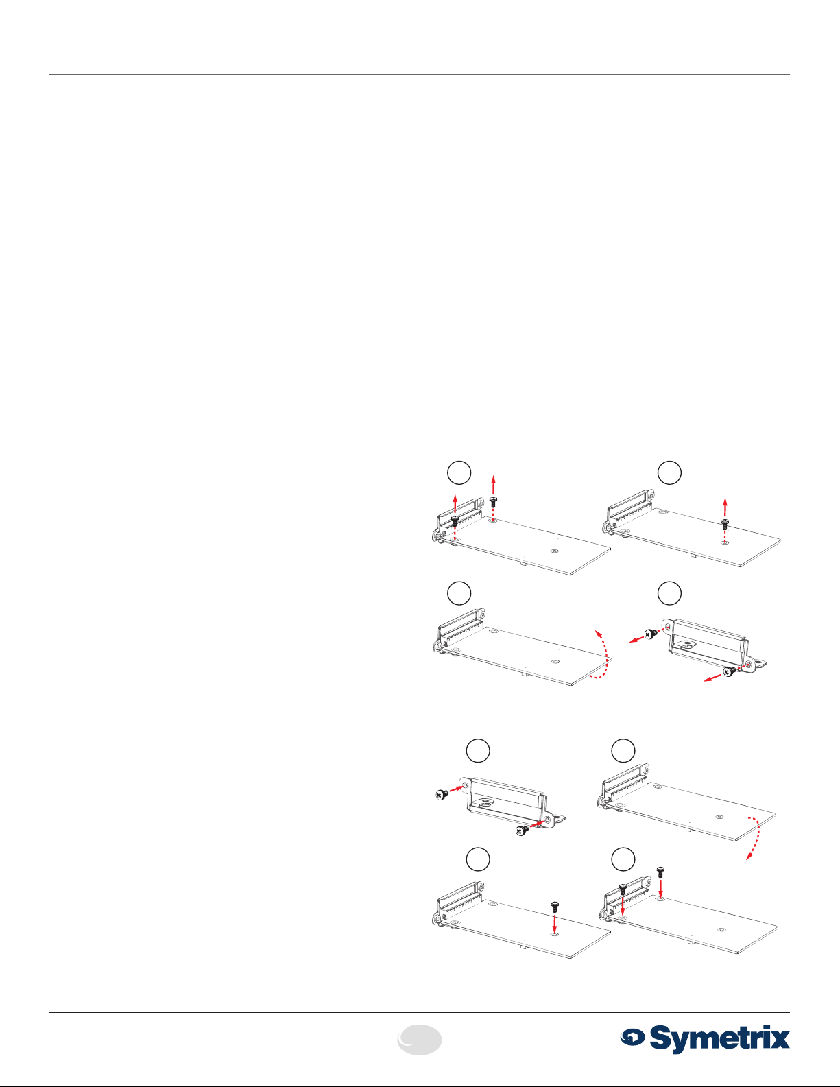
Remove Installed Card
Install New Card
Getting Started
ESD Warning
This product can be damaged by electrostatic discharge
(ESD). When handling, care must be taken so that the
devices are not damaged. Damage due to inappropriate
handling is not covered by the warranty.
The following precautions must be taken:
• Do not open the protective conductive packaging until
you have read the following, and are at an approved anti static work station.
• Use a conductive wrist strap attached to a good earth
ground.
• Always discharge yourself by touching a grounded bare
metal surface or approved anti-static mat before picking
up an ESD-sensitive electronic component.
• Use an approved anti-static mat to cover your work
surface.
Card Set-up and Configuration
Once you are properly grounded, follow this sequence of
steps to properly set-up and configure SymNet I/O cards in
your Radius AEC or Edge frame.
First, make sure the unit is powered down. Next, you must
remove the lid. To do this, 3 Phillips head screws need to be
removed from the top of the frame. Slide the lid back and
then up when removing. There is a lip that holds the front
down to the chassis.
If your Radius AEC or Edge unit has blank filler panels in the
card slots, unscrew and remove them by removing the two
black screws located on the outside of the frame.
To remove an installed card, first remove the 2 stainless
steel screws that mount the card bracket to the card. These
screws are located on the inside.
Next remove the stainless steel Phillips head screw from the
top of the card. Gently pull the card up to disconnect the 50pin connector. The card is no longer attached to the frame.
Carefully remove the card from the chassis.
Remove the bracket for the I/O card by removing the two
black screws located on the outside of the frame. Unused
I/O card bays must have a blank filler panel installed when
operating a Radius AEC or Edge unit.
To install a new card, mount the bracket for the new I/O card
to the frame chassis using the two black screws provided.
Next, align and feed the connectors on the I/O card through
the opening in the bracket and align the single screw hole in
the card with the standoff on the motherboard. Look through
this hole and align with the standoff and then, carefully, apply
an even downward pressure until you feel the card seat into
the 50-pin socket. You will likely need to carefully move the
board side to side to align the 50-pin connector. Use one
of the stainless steel screws provided and mount the board
to the standoff. Do not over tighten this screw. The 50-pin
connector on the SymNet I/O cards should not be under any
tension when properly installed.
Now, install and tighten the 2 remaining stainless steel
screws that mount the bracket to the card. This should
ALWAYS be the last step before replacing the lid.
Finally, replace the lid.
The IN, OUT, AEC and DIGI LEDs on the front of the Radius
AEC or Edge frame will illuminate in combination to indicate the
card type installed. For example, an IN illuminates to indicate an
analog mic/line input card, whereas IN and DIGI illuminate to
indicate a digital input card. The IN and OUT LED’s illuminate to
indicate a analog telephone interface card. If the card is installed
properly, the card type LED(s) will illuminate.
21
43
21
3
4
6408 216th Street SW | Mountlake Terrace, WA 98043 USA
T +1.425.778.7728 F +1.425.778.7727 | www.symetrix.co
2
Page 3

QUICK START GUIDE: SymNet I/O Card
Connections
4 Channel Analog Input Card
Connections:
Using standard mic/line cables terminated on one end with
terminal block connectors and appropriate connectors for
your mic/line sources on the other end, connect the terminal
block ends into the Analog Mic/Line Inputs on the card and
the opposite ends into your source devices’ outputs. Refer
to the help module included in all Symetrix software for more
information on the Edge 4 Channel Analog Input Card and
audio wiring.
4 Channel Analog Output Card
Connections:
Using standard mic/line cables terminated on one end with
terminal block connectors and appropriate connectors for
your destination devices on the other end, connect the
terminal block ends into the Analog Line Outputs on the
card and the opposite ends into your destination devices’
inputs. These outputs are +4 dBu balanced line level outputs
by default. If you need an unbalanced output, or more
information on the Edge 4 Channel Analog Output Card,
refer to the analog audio wiring diagrams located in the help
module included in all Symetrix software.
4 Channel Digital Input Card
Input(s) on the card. Refer to the help module included in
all Symetrix software for more information on the Edge 4
Channel Digital Output Card and audio wiring.
4 Channel AEC Input Card
Connections:
Using standard mic/line cables terminated on one end with
terminal block connectors and appropriate connectors
for your mic/line sources on the other end, connect the
terminal block ends into the AEC Inputs on the card and the
opposite ends into your source devices’ outputs. Refer to
the help module included in all Symetrix software for more
information on the Edge 4 Channel AEC Input Card and
audio wiring.
2 Line Analog Telephone Interface Card
Connections:
Using a standard telephone cord terminated with RJ11
(6P6C) connectors, connect one end to the Line port on the
Analog Telephone Interface card and opposite end to the
telephone network (wall jack). Optionally, connect a standard
analog telephone, dialer, audible and/or visual ringing device
to the Set port of the Analog Telephone Interface Card using
another telephone cord.
Connections:
Using 100-Ohm (balanced, AES) or 75-Ohm (unbalanced
S/PDIF) cables terminated on one end with terminal block
connectors and appropriate connectors for your digital
sources on the other end, connect the terminal block ends
into the Digital Inputs on the card and the opposite ends
into your source devices’ outputs. These inputs have a
nominal sample rate of 48 kHz. They will accept any input
ranging from 12 to 96 kHz and sample rate convert to the
nominal rate of 48 kHz. Refer to the help module included
in all Symetrix software for more information on the Edge 4
Channel Digital Input Card and audio wiring.
4 Channel Digital Output Card
Connections:
Using 100-Ohm (balanced, AES) or 75-Ohm (unbalanced,
S/PDIF) cables terminated on one end with terminal block
connectors and appropriate connectors for your destination
devices on the other end, connect the terminal block ends
into the Digital Outputs on the card and the opposite ends
into your destination devices’ inputs. These outputs use
a sample rate of 48 kHz by default. If you need a different
sample rate, connect an appropriate Word Clock, AES-3/11
clock or S/PDIF clock source to the corresponding Clock
Note: At this time, the SymNet 2 Line Analog Telephone
Interface Card is only certified for use with US and Candian
Public Switched Telephone Networks.
3
Page 4

QUICK START GUIDE: SymNet I/O Card
Warranty and Service
The Symetrix Limited Warranty
Symetrix, Inc. expressly warrants that the product will be free from
defects in material and workmanship for three (3) years from the date
the product is shipped from the factory. Symetrix’ obligations under this
warranty will be limited to repairing or replacing, at Symetrix’ option,
the part or parts of the product which prove defective in material or
workmanship within three (3) years from the date the product is shipped
from the factory, provided that the Buyer gives Symetrix prompt notice
of any defect or failure and satisfactory proof thereof. Products may be
returned by Buyer only after a Return Authorization number (RA) has
been obtained from Symetrix. Buyer will prepay all freight charges to
return the product to the Symetrix factory. Symetrix reserves the right
to inspect any products which may be the subject of any warranty claim
before repair or replacement is carried out. Symetrix may, at its option,
require proof of the original date of purchase (dated copy of original
retail dealer’s invoice). Final determination of warranty coverage lies
solely with Symetrix. Products repaired under warranty will be returned
freight prepaid via commercial carrier by Symetrix, to any location within
the continental United States. Outside the continental United States,
products will be returned freight collect.
The foregoing warranties are in lieu of all other warranties,
whether oral, written, express, implied or statutory. Symetrix,
Inc. expressly disclaims any IMPLIED warranties, including
fitness for a particular purpose or merchantability. Symetrix’
warranty obligation and buyer’s remedies hereunder are SOLELY
and exclusively as stated herein.
This Symetrix product is designed and manufactured for use in
professional and studio audio systems and is not intended for
other usage. With respect to products purchased by consumers for
personal, family, or household use, Symetrix expressly disclaims all
implied warranties, including, but not limited to, warranties of
merchantability and fitness for a particular purpose.
This limited warranty, with all terms, conditions and disclaimers set
forth herein, shall extend to the original purchaser and anyone who
purchases the product within the specified warranty period.
Symetrix does not authorize any third party, including any dealer or
sales representative, to assume any liability or make any additional
warranties or representation regarding this product information on
behalf of Symetrix.
This limited warranty gives the buyer certain rights. You may have
additional rights provided by applicable law.
Note: Some Symetrix products contain embedded software or apps
and may also be accompanied by control software intended to be run
on a personal computer. Said software is specifically excluded from this
warranty.
Servicing Your Symetrix Product
If you have determined that your Symetrix product requires repair
services and you live outside of the United States please contact your
local Symetrix dealer or distributor for instructions on how to obtain
service.
If you reside in the United States, please contact Symetrix Customer
Service Department for a Return Authorization (RA) number and
additional in-warranty or out-of-warranty repair information.
Tel: +1.425.778.7728 (PST)
Email: support@symetrix.co
Limitation of Liability
The total liability of Symetrix on any claim, whether in contract,
tort (including negligence) or otherwise arising out of, connected
with, or resulting from the manufacture, sale, delivery, resale, repair,
replacement or use of any product will not exceed the price allocatable
to the product or any part thereof which gives rise to the claim. In
no event will Symetrix be liable for any incidental or consequential
damages including but not limited to damage for loss of revenue, cost
of capital, claims of customers for service interruptions or failure to
supply, and costs and expenses incurred in connection with labor,
overhead, transportation, installation or removal of products, substitute
facilities or supply houses.
6408 216th Street SW | Mountlake Terrace, WA 98043 USA
T +1.425.778.7728 F +1.425.778.7727 | www.symetrix.co
4
 Loading...