

Page 1
Quick Start
AVIS:
NE PAS OUVRIR
Il ne se trouve a l’interieur aucune piece pourvant entre reparée l’usager.
SEE OWNERS MANUAL. VOIR CAHIER D’INSTRUCTIONS.
S’adresser a un reparateur compétent.
RISQUE DE CHOC ELECTRIQUE
No user serviceable parts inside. Refer servicing to qualified service personnel.
CAUTION
WARNING:
TO REDUCE THE RISK OF FIRE OR
ELECTRIC SHOCK DO NOT EXPOSE
THIS EQUIPMENT TO RAIN OR MOISTURE
DO NOT OPEN
RISK OF ELECTRIC SHOCK
SymNet
™
To download the latest version of SymNet designer, the Windows application that
controls SymNet hardware go to www.symetrixaudio.com/Products/symnet.htm.
Before You Begin
What Ships in the Box
R A SymNet hardware device
R SymNet Designer CD-ROM
(Windows)
R A detachable power cable
R This Quick Start Guide
NOTE - You may complete the
warranty registration online at
www.symetrixaudio.com.
What you’ll need to run SymNet
Designer software
R A Windows PC with 300MHz or
higher Pentium and:
R WIN 98SE, WIN ME, or WIN
2000.
R 10MB -15MB free storage space
R 1024x768 graphics capability
R 16 bit or higher colors
R CD ROM drive or Internet connec-
tion
R 32MB RAM or more as required
by your operating system
R An available serial port capable
of operating at 57.6 or 115.2
kilobaud
R A cable to connect the RS-232
serial port of your PC to the
SymNet’s RS-232 input. The
SymNet RS-232 input is a female
DB9 connector.
Getting Help
SymNet Designer, the Windows
application that controls SymNet
hardware includes a help le which
acts as a complete user’s guide for
both hardware and software.
If you have questions beyond the
scope of the help le, contact our
Technical Services Group in the
following ways:
Tel (425) 787-3222
8:00 am to 4:30 pm
Pacic Time
Email tech@symetrixaudio.com
Web www.symetrixaudio.com
Operator Safety Summary
• Read these instructions.
• Heed all warnings.
• Keep these instructions.
Power Source. SymNet™ Audio Matrix
hardware uses a switching power supply
that automatically adjusts to the applied
voltage. Ensure that your AC mains
voltage is somewhere between 100240VAC, 50-60Hz.
Grounding. This product is intended to
operate from a power source that does
not apply more than 250V rms between
the power supply conductors or between
either power supply conductor and
ground. A protective ground connection,
by way of the grounding conductor in
the power cord, is essential for safe
operation.
Do not defeat the safety purpose of
the polarized or gournding-type plug.
A polarized plug has two blades with
one wider than the other. A grounding
type plug has two blades and a third
grounding prong. The wide blade of the
third prong is provided for your safety.
If the provided plug does not t into
your outlet, consult an electrician for
replacement of the obsolete outlet.
Fuse. This product contains no user
servicable fuse.
Danger from Loss of Ground. If the
protective ground connection is lost, all
accessible conductive parts, including
knobs and controls that may appear to be
insulated, can render an electric shock.
Proper Power Cord. Use only the
power cord and connector specied for
the product and your operating locale.
Use only a cord that is in good condition.
Protect the power cord from being walked
on or pinched, particularly at the plug,
convenience receptacle, and the point
where the cord exits from the apparatus.
Operating Location. Do not operate
this equipment under any of the following
conditions: explosive atmospheres,
in wet locations, in inclement weather,
improper or unknown AC mains voltage,
or if improperly fused. Do not install near
any heat source such as radiators, heat
registers, stoves, or other apparatus
(including ampliers) that produce heat.
Unplug this apparatus during lightning
storms or when unused for long periods
of time. Do not use this apparatus near
water. Do not expose this apparatus
Revision A.04 1 of 9
to dripping or splashing. Place no
objects lled with liquids, such as vases,
upon this apparatus. Do not block any
ventilation openings.
Stay Out of the Box. To avoid
personal injury (or worse), do not
remove the product covers or panels.
Do not operate the product without the
covers and panels properly installed.
Only use accessories specied by the
manufacturer. Clean only with dry cloth.
User-Serviceable Parts. There are
no user serviceable parts inside the
SymNet™ Audio Matrix. There are no
adjustments or jumpers to set within
the chassis. Settings are stored in non
-volatile ram and no back-up battery
is required. In case of failure, refer all
servicing to the factory. Servicing is
required when the SymNet™ Audio
Matrix has been damaged in any way,
such as when liquid has been spilled or
objects have fallen into the apparatus,
the apparatus has been exposed to rain
or moisture, does not operate normally,
or has been dropped.
Equipment Markings
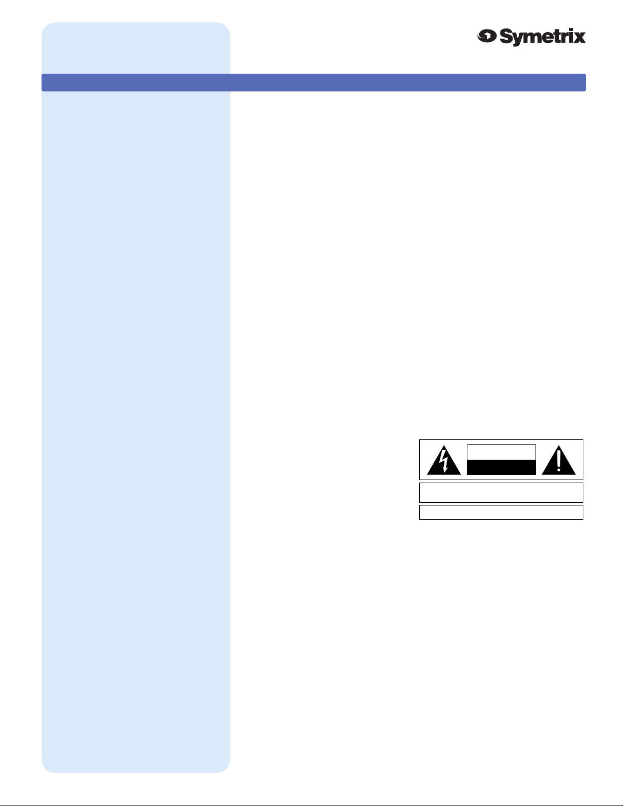
The lightning ash with arrowhead
symbol within an equilateral triangle is
intended to alert the user of the presence
of uninsulated “dangerous voltage”
within the product’s enclosure that may
be of sufcient magnitude to constitute
a risk of electric shock to persons. The
exclamation point within an equilateral
triangle is intended to alert the user of
the presence of important operating and
maintenance (servicing) instructions in
the literature accompanying the product
(i.e., this quick start guide).
Warning
To reduce the risk of re or
electric shock, do not expose this
apparatus to rain or moisture.
Page 2

Quick Start
SymNet
™
To download the latest version of SymNet designer, the Windows application that
controls SymNet hardware go to www.symetrixaudio.com/Products/symnet.htm.
Introduction 2 of 9
SymNet™ Audio Matrix
The Symetrix SymNet™ Audio Matrix is a family of
network linkable audio matrix processors intended for
the installed sound market. SymNet is a mixing, routing,
processing platform using Digital Signal Processing
(DSP) to implement the following audio processing
blocks:
• Dynamics: Compressors, Limiters, Gates, Duckers,
Downward Expanders, AGC
• Parametric Equalizers
• Filters: Highpass, Lowpass, Shelf
• Crossovers: two to four-way
SymNet™ Designer
SymNet™ Designer is an easy to use graphical user
interface (GUI) that uses drag-and-drop techniques to
quickly and easily select and connect the processing
blocks needed for a working system. You download
the nished design into the SymNet™ hardware via an
RS232 connection and you’re off and running. Up to eight
different congurations can be saved in one unit, and
these can be recalled during use to change conguration,
routing, settings, or to control an external device. Since
the conguration les are stored in the hardware, you
can walk up to a SymNet™ installation, plug your laptop
computer into the RS232 port, and download that unit’s
conguration les.
Revision A.04
• Delays
• Mixers: Stereo, Mono, LCR, Matrix
• Signal Generators: Sine, Square, Triangle, Pink noise,
White noise.
• Input Selector Switching
• Level Controls
• Meters and Oscilloscopes
• Comprehensive Remote Control Functions
• Realtime clock driven Event Scheduler
Audio processing takes place after 24-bit Sigma-Delta
conversion using 40-bit oating point processing. Floating
point processing eliminates internal dynamic range
problems caused by overow or attenuation during digital
signal processing operations.
There are three processors in the Audio Matrix family:
Up to 8 SymNet™ can be linked using SymLink, an ultrafast 64-channel audio/data backbone used to connect
units in adjacent racks using CAT5 cabling. SymLink is a
ring network; all hardware is self-contained and no hubs
or interface cards are required.
This Quick Reference Guide is intended for the installer’s
use during installation. Further details about SymNet
Designer can be found in the program’s help system.
SymNet Designer can be found on the CD-ROM shipped
with the hardware or downloaded from the Symetrix
website: http://www.symetrixaudio.com.
• The SymNet 8x8 processor. 8-inputs, 8-outputs,
onboard DSP, SymLink linkable.
• The SymNet 8in processor: 8-inputs, onboard DSP,
SymLink linkable
• The SymNet 8out processor: 8-outputs, onboard DSP,
SymLink linkable
Page 3
Quick Start
������
SymNet
™
To download the latest version of SymNet designer, the Windows application that
controls SymNet hardware go to www.symetrixaudio.com/Products/symnet.htm.
Hardware Installation
Mechanical
Item Discussion Remarks
Space Required 1U (WDH: 48.26 cm x 21.59cm
x 4.369cm / 19 in x 8.5 in x 1.72
in) Depth measurement does not
include connector allowance.
Electrical 100-24VAC, 50-60Hz, 100W
maximum.
Ventilation Fan located at equipment right,
pulls cold air into unit. Air exit at
equipment left.
Weight 3.0kg / 6.6 lbs net.
Allow 1-inch additional depth for Euroblock connectors.
Additional depth may be required depending on your
particular DB9 connector. Allow 1U (1.72 in, 4.369cm)
free space above and below unit for proper ventilation.
No line voltage switching is required.
Ensure that the left and right equipment sides are
unobstructed (2”, 5.08cm minimum clearance). The
ventilation should not be impeded by covering the
ventilation openings with items such as newspapers,
tablecloths, curtains, etc.
Connections
Item Discussion Remarks
Binary outputs (relay
and open collector) and
analog control inputs
All use Euroblock connectors.
Symetrix part number 039003
Connectors come in 3-pin modules. Connectors
included with unit.
Revision A.04
3 of 9
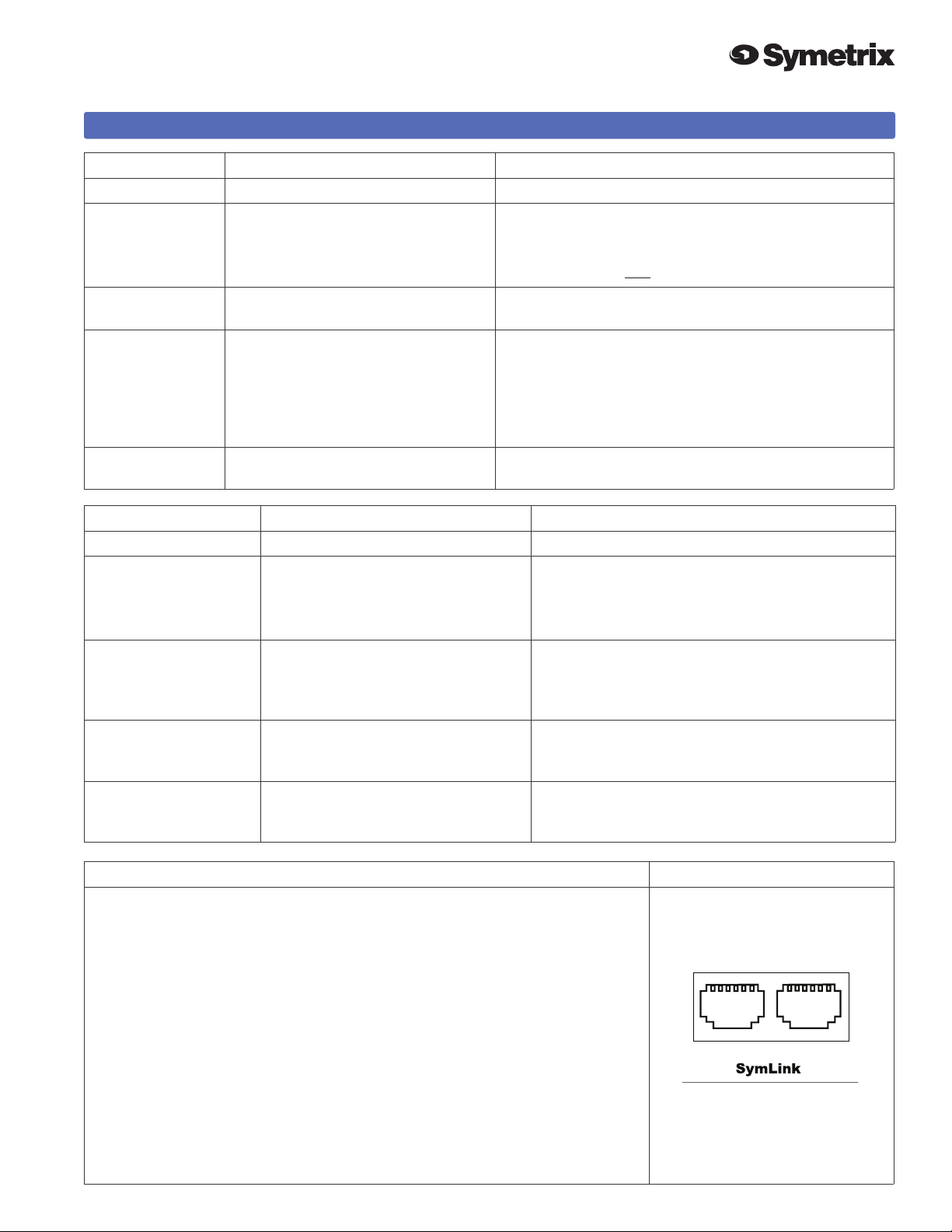
RJ45 CAT5 shielded network cabling
SymLink
RS-232 DB9 female d-sub connector on unit Same connector used on front panel.You need
AC mains Opposite end as required for your locale.
required. Uses standard RJ45 ‘straight-through’ wiring. 10
meter length limit.
pins: 2, 3, 5, 7, 8, (wired ‘straight-through’).
Cable included with unit.
Interconnecting Multiple Units via SymLink
This is relatively straightforward, however the following points are important to
keep in mind:
• SymLink is a ring network unlike EtherNet which uses a hub and spoke
topology making a single connection to each device from the hub. Each device
on a SymNet network has two connections: TRANSMIT and RECEIVE. With
SymNet the last unit’s TRANSMIT connector must connect to the rst unit’s
RECEIVE connector.
• SymLink cables must be shielded, and are limited to 10 meters length (each).
• It is not necessary to follow any particular numeric order when interconnecting
units. This may be helpful when units are located in adjacent racks.
• Each unit must have a different Unit ID number. The master unit must be
Unit ID #1. Remember where this unit is, because the PC running SymNet
Designer must be connected there.
Page 4

Quick Start
TRANSMIT RECEIVE
SymLink
RS-232
MANUFACTURED BY SYMETRIX, INC. LYNNWOOD, WA USA
THIS UNIT CONTAINS NO USER SERVICEABLE PARTS.
FA
BRIQUÉ AUX E.-U. PAR SYMETRIX, INC. LYNNWOOD, WA
PA
S DES ELEMENTS SERVIABLE PAR UTILISATEUR
DEVICE
CONFIG
---- RS-485 ---- --- RELAY 3 --- --- RELAY 2 --- --- RELAY 1 ---
BINARY OUTPUTS
100-240
VAC
50/60 Hz
INPUT
75 WATTS
MAXIMUM
--- CHAN 8 --- --- CH
A
--- CHAN 4 --- --- CHA
N
A
D
D
R
16
8
4
2
1
(UNASSIGNED)
MASTER/SLAVE
BAUD
ANALOG
B
A
C NC NO C NC NO C NC NO
IN
+V
IN
OC1
OC2
OC3
OC4
OC5
OC6
TM
8
7
6
5
4
3
2
1
8X8 DSP
--- CHAN 8 --- --- CHAN 7 --- --- CHAN 6 --- --- CHAN 5 ---
--- CHAN 4 --- --- CHAN 3 --- --- CHAN 2 --- --- CHAN 1 ---
ANALOG CONTROL INPUTS
IN
+V
IN
+V
IN
+V
IN
+V
--- CHAN 4 --- --- CHAN 3 --- --- CHAN 2 --- --- CHAN 1 ---
ANALOG OUTPUTS
--- CHAN 4 --- --- CHAN 3 --- --- CHAN 2 --- --- CHAN 1 ---
ANALOG INPUTS
--- CHAN 8 --- --- CHAN 7 --- --- CHAN 6 --- --- CHAN 5 ---
--- CHAN 8 --- --- CHAN 7 --- --- CHAN 6 --- --- CHAN 5 ---
SymNet
™
To download the latest version of SymNet designer, the Windows application that
controls SymNet hardware go to www.symetrixaudio.com/Products/symnet.htm.
Hardware Installation ... continued 4 of 9
Revision A.04
SymNet Rear Panel (left)
SymNet Rear Panel (right)
Page 5

Quick Start
SymNet
™
To download the latest version of SymNet designer, the Windows application that
controls SymNet hardware go to www.symetrixaudio.com/Products/symnet.htm.
Hardware Installation ... continued 5 of 9
Revision A.04
DIP Switch Settings
An eight-position DIP switch is located in the middle of the rear panel of the
SymNet™ hardware. It determines serial port speed, master/slave mode,
unit address, and factory rmware enable. The ON setting is to the left as
you face the rear of the unit.
Note: after changing any DIP
switch setting, reboot the
hardware by disconnecting it from
AC power and then reconnecting
it.
Switch Number, bottom to top What does it do? Remarks
1 - BAUD Sets baud rate of front panel RS232
Serial Port.
2 - MASTER / SLAVE Off = MASTER, On = SLAVE Unit with ADDR = 1 must be the
3-7 - ADDR (Device Address) Each unit must have a unique
address. These switches set that
number, in binary form, using the bit
values labeled on the equipment.
On = 1, Off = 0.The device address
equals the number programmed via
SW3-7.
8 - Use Factory Firmware On = Use Factory OS
Off = Use upgraded OS
Off=115200 baud, On=57600 baud.
Must match setting in SymNet
Designer.
MASTER. All other units must be
SLAVES.
SW3 - 1
SW4 - 2
SW5 - 4
SW6 - 8
SW7 - 16
All switches OFF = device address 0
(zero).
All switches are ON = device address
31.
Set to OFF unless instructed
otherwise by tech support.
RS-232 Settings
The rear panel DIP switch determines the baud rate
(speed) of the front panel RS-232 connector. After
changing the setting of the DIP switch, you must reboot
the hardware by removing and restoring AC power to
the unit.
The cable connecting to the host PC is a simple DB-9
extension cable, with like pins wired to like pins, with
male and female connectors at the ends. You can
purchase this at any computer store. Generally all
pins are wired, which is permissible. At a minimum,
you need pins 2, 3, 7, and 8 wired. Pin 5 (ground) is
optional.
You may connect your host PC to either the front or
rear panel RS-232 port.
Test your RS-232 connection by trying to download to
the hardware. You should see the yellow RS-232 LED
on the front panel blink.
Page 6

Quick Start
SymNet
™
To download the latest version of SymNet designer, the Windows application that
controls SymNet hardware go to www.symetrixaudio.com/Products/symnet.htm.
Hardware Installation ... continued
Analog Input / Output Connections
Item Description Details Remarks
Analog
Inputs
Analog
Outputs
Analog
Control
Inputs
Balanced-bridging input
accepts signal levels from
mic (-50dBu nominal)
through line (+4dBu
nominal). 48V phantom
power available.There is
20 dB headroom past the
signal level selected. At
unity gain (+4dBu setting),
the maximum input level is
+24dBu.
Balanced line output
delivers +24dBu maximum
level. Nominal level can
be software adjusted for
professional or consumer
line levels or mic level.
High-impedance input
accepts 0-10V positive
DC signals.10V reference
voltage available at rear
panel interface.
Input impedance:
>6.66k balanced, >3.3k
unbalanced. The input
topology uses a balanced
instrumentation amplier.
Both inputs are identical
and symmetrical in terms
of impedance and shunt
capacitance. Set input
level capability, phantom
power, and gain via control
software.
Output source impedance:
204-ohms balanced, 102ohms unbalanced.The
output topology is a chain
of inverters, emulating
a grounded center-tap
transformer secondary.
Use with external
potentiometer (10k linear
taper) or external voltage
source (0-10V). See Rear
Panel for connections.
For unbalanced use, either reference the
minus input terminal to the signal source
ground (preferred) or ground the minus input
to the adjacent ground terminal. Using the
second method deprives you of the common
mode rejection inherent in a balanced input,
even when coming from an unbalanced
source.
For unbalanced use oat (do not connect) the
minus output terminal. Note that unbalanced
usage results in 6dB lower output level.
Revision A.04
6 of 9
Binary, Relay and RS485 Outputs
Item Discussion Remarks
Binary Outputs Six NPN transistor outputs, cleverly
wired to allow operation as open
collector output for relay coil driving
or for sourcing LED drive current.
Collector and ground connections
furnished.
These outputs can also drive an LED
directly. Current limit resistor not
needed.
Relay Outputs Three SPDT relay contacts.
Contact rating: 3A, 24VDC,
resistive0.3A, 60VDC, resistive
RS-485 I/O Connect to RS-485 system. 2-signal lines and ground provided.
2N4401 transistors. Current must be
< 50mA, 24V maximum.
Control software determines how
these are used.
If you’re driving a relay, be sure to
include a reversed biased diode
connected across the relay coil.
Connect the LED from the output to
ground.
SymNet Designer determines how
these are used.
Do not use at 120VAC.
See SymNet Designer Help Module
or www.symetrixaudio.com for
complete protocol.
Page 7

Quick Start
SymNet
™
To download the latest version of SymNet designer, the Windows application that
controls SymNet hardware go to www.symetrixaudio.com/Products/symnet.htm.
SymNet Designer Software
Software Installation
The Symetrix SymNet Designer software provides
real-time control over multiple audio functions from a
Windows 95/98/2000 PC environment.
Use one of the following procedures to install the SymNet
Designer on your computer.
From the SymNet Designer CD-ROM:
1. The software should autorun after inserting the CDROM into your computer’s CD-ROM drive.
2. If the software does not autorun, then Click on the
Start button, Run d:\setup
(if your CD-ROM drive isn’t d:, then substitute its drive
letter)
From the Symetrix Website (http://
www.symetrixaudio.com):
1. Download the SymNet™ Designer program le.
2. From the Start button, Run the le/program that you
just downloaded to start the Setup program.
The software always starts up in ofine mode.
Regardless, you can explore the software, experiment to
your heart’s content, and perhaps even get useful work
done. You can save any congurations that you create
to a le that can be downloaded later into an operating
SymNet system.
Revision A.04
7 of 9
Drag and drop signal processors into the conguration
page. Connect them together by clicking on a connection
point and moving the mouse in the direction you want the
wire to run. Make corners by clicking at the corner and
moving off in a new direction. Terminate a wire by clicking
on the terminating connection point or by hitting the ESC
key or right mouse button. Right click on an existing wire
to make a tee connection.
Once you’ve completed your design, download it to the
SymNet unit by clicking the Download! item in the menu
bar located at the top of the screen. Double click on
processors on the conguration page to see and change
their settings.
Note: There are a lot of useful functions available in the
mouse right-click. Explore! That’s the ultra-condensed
version. You’ll nd more complete information in SymNet
Designer’s help system.
Internal Hardware Memory
SymNet™ saves its settings in internal Flash Memory,
allowing it to recall settings through a power-down/up
cycle. Unlike static ram, the ash memory does not
require batteries, and is designed to retain its memory for
the life of the product.
If there is a SymNet unit connected, you can go to online,
and upload the conguration le from the SymNet unit(s).
Once you have a unit connected, you can also work
in real time, which allows you to hear adjustments and
settings as you make them.
Using SymNet Desginer
Once the installation process is complete, you should
have an icon on your desktop, and a program item on the
Start menu. Click on the SymNet icon and you’re ready to
begin.
SymNet™ Designer is mostly self explanatory. The
Conguration Screen represents all SymNet units in a
system. Each unit can store up to eight congurations.
Using the insert tab of the tool kit (left-hand) window, you
select the SymNet unit that you wish to congure and
drag it to the conguration page. Double clicking on the
unit opens it, and causes the tool kit to display all the
different signal processors available. The tool kit window
is context sensitive. It always displays the items that can
be placed in the current window. You can switch to the
Browser tab of the tool kit to navigate to all of the relevant
windows opened.
© 2001, 2002 Symetrix, Inc.
All rights reserved.
Printed in the United States of America
Symetrix Part Number 538x8s1A04
The information in this guide is subject to change without
notice. Symetrix, Inc. shall not be liable for technical or
editorial errors or omissions contained herein; nor is it liable
for incidental or consequential damages resulting from the
furnishing, performance, or use of this material.
Mention of third-party products is for informational
purposes only and constitutes neither an endorsement nor
a recommendation. Symetrix assumes no responsibility with
regard to the performance or use of these products.
Under copyright laws, no part of this user guide may be
reproduced or transmitted in any form or by any means,
electronic or mechanical, without permission in writing from
Symetrix, Inc. If, however, your only means of access is
electronic, permission to print one copy is hereby granted.
Permission to copy the Architects and Engineers Speciciations
for written proposals specifying equipment for sound
reinforcement systems is, also, granted.
Product names mentioned herein may be trademarks and/or
registered trademarks of their respective companies and/or
Symetrix, Inc.
Page 8

Quick Start
SymNet
™
To download the latest version of SymNet designer, the Windows application that
controls SymNet hardware go to www.symetrixaudio.com/Products/symnet.htm.
Product Registration 8 of 9
To register your product, complete the information
below and mail or fax copies of both this page and your
sales receipt to:
Symetrix, Inc.
ATTN: Product Registration
14926 35th Ave West
Lynnwood, WA 98037 USA
(425) 787-3211
Or ... register online at www.symetrixaudio.com
Model # Serial #
Dealer Dealer City
Your Name Date of Purchase
Your Company Your Telephone Number
Title / Department
Your Email Address
Mailing Address Country
City
State
Postal Code
Revision A.04
Where is this product being used? (check all that apply) What was the deciding factor in choosing this
Symetrix product?
q Hotel q Auditorium q Feature set
q Paging System q Casino q Price
q School q Church q Specications
q Stadium / Arena q Transportation Terminal q Reliability
q Conference Center q Other __________________ q Reputation
q Availability
q Warranty
q Other ______________________________
Page 9

Quick Start
SymNet
™
To download the latest version of SymNet designer, the Windows application that
controls SymNet hardware go to www.symetrixaudio.com/Products/symnet.htm.
Delclaration of Conformity
Declaration of Conformity
We, Symetrix, Incorporated, 14926 35th Ave West, Lynnwood, WA, 98037,
USA, delcare under our sole responsibility that the products:
• SymNet 8x8 DSP
• SymNet 8in DSP
• SymNet 8out DSP
to which this declaration relates, are in conformity with the following
standards:
EN 60065
Safety requirements for mains operated electronic and related
apparatus for household and similar general use.
EN 50081-1
Electromagnetic compatibility - Generic emission standard
Part 1: Residential, commercial, and light industry.
EN 50082-1
Electromagnetic compatibility - Generic immunity standard
Part 1: Residential, commercial, and light industry.
Revision A.04
9 of 9
EN 55022
Limits and methods of mesurement of radio interference
characteristics of information technology equipment.
The technical construction le is maintained at:
Symetrix, Inc.
14926 35th Ave. West
Lynnwood, WA, 98037-2303
USA
The authorized representative located within the European Community is:
World Marketing Associates
P.O. Box 100
St. Austell, Cornwall, PL26 6YU, England
Date of issue: 15 March, 2002
Place of issue: Lynnwood, Washington, USA
Authorized signature:
Dane Butcher, President, Symetrix Incorporated.
 Loading...