

Page 1

528E Voice Processor
User’s Guide
528E
Page 2

Table of Contents
Chapter 1 Introduction 1
Chapter 2 Operator Safety Summary 2
Chapter 3 Fast Setup 3
Chapter 4 Front Panel Overview 4
Chapter 5 Rear Panel Overview 8
Chapter 6 Voice Processing Tutorial 10
Chapter 7 Using the 528E 20
Chapter 8 Applications 28
Chapter 9 Technical Tutorial 32
Chapter 10 Troubleshooting 36
Chapter 11 Specifi cations 37
Chapter 12 Warranty & Service 39
Appendix A Disassembly Instructions 41
and Output Level Switch
Appendix B Declaration of Conformity 42
© April 2000-01 Symetrix, Inc.
All rights re served.
Symetrix Part Number 53528-0F00
The information in this guide is subject to change
without notice. Symetrix, Inc. shall not be liable
for technical or editorial errors or omissions
contained herein; nor is it liable for incidental or
con se quen tial damages resulting from the furnishing, per for mance, or use of this material.
Mention of third-party products is for in for ma tion al purposes only and constitutes neither an
en dorse ment nor a recommendation. Symetrix
assumes no re spon si bil i ty with regard to the performance or use of these products.
Under copyright laws, no part of this user guide
may be reproduced or transmitted in any form or
by any means, electronic or me chan i cal, without
528E
permission in writing from Symetrix, Inc. If,
however, your only means of access is elec tron ic,
permission to print one copy is hereby granted.
14926 35th Ave. West
Lynnwood, WA 98037 USA
Tel (425) 787-3222
Fax (425) 787-3211
www.symetrixaudio.com
Page 3

IntroductionChapter 1
15
30
800
8K
5
0
BYPASS
40
0
+20
10
16
.3
500
9201636
+15
6.3K
+15
160.315
680
.3
15
+15
+15-15
0
C
OM
OUT
S
CO
S
CO
O
H
Q
Q
Y
BANDWIDTH
Y
BANDWIDTH
T
BANDWIDTH
T
OUT
)
OUT
Q
6
R
D
M
528E
CE
SSOR
R
UT
UM
P
½
.
QU
Y
UT
R
O
US
S.
OUTPUT S
E
UT
OUTPUT
U
D
OUTPUT
UT
OUTPUT
D
S
N
E
R
N
OUTPUT
UT
S
E
OUTPUT
UT
SS
UT
SS
OM
R
8V
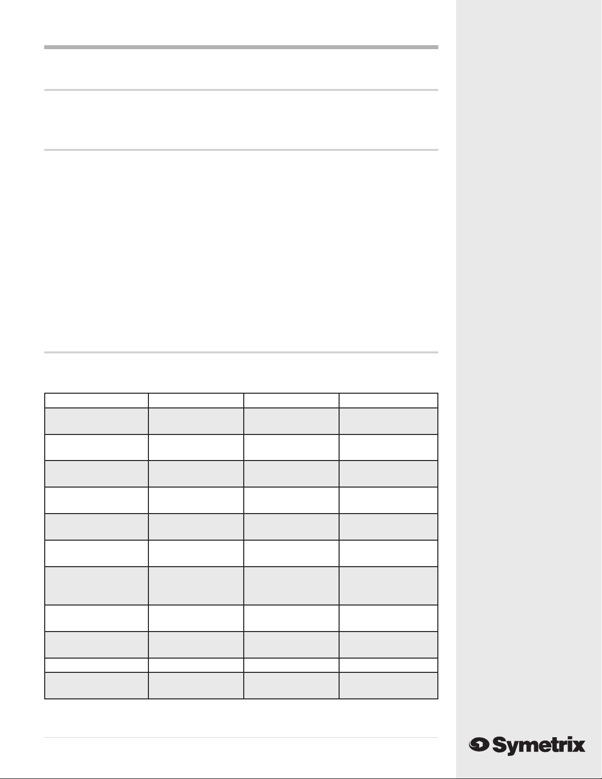
The Symetrix 528E is a single-channel Voice Processor intended for use in voice-over studios,
broad cast studios, sound-reinforcement, music and speech recording, and post-production. Simply
stated, the 528E consists of a high-quality microphone preamp coupled to a three-band parametric equalizer, a de-esser, and a dynamic range processor. It is everything you would have at your
disposal in a world-class mixing console. The 528E accepts both mic and line inputs. Of course,
while we use the term “Voice Processor” for the 528E, it is perfectly at home with any signal, vocal
or not.
The microphone input uses a balanced-transformerless design using an integrated circuit spe cifi cal ly developed for this application. The 528E’s microphone input works with any phantom-powered condenser microphone or any low-impedance microphone having a balanced, fl oating output.
The line input uses a balanced transformerless design. The line input’s design uses matched resistors to attain a high, wideband, CMRR (common-mode rejection ratio) and multistage RFI fi lters to
prevent Radio Frequency interference problems.
The de-esser operates by selectively removing the high frequencies from the input signal when
sibilant sounds are present and exceed the threshold level. The fi lter frequency can be varied over a
wide range to accommodate different speakers and languages.
The dynamic range processor combines an interactive compressor/limiter and a downward ex pand er. Typically, the downward expander helps reduce studio noise as well as the artifacts of close
miking. The compressor/limiter gives you overall control over the dynamic range of the output
signal and helps maintain a high overall signal level. The three-band parametric equalizer is a reciprocal-curve design. An unusual leapfrog topology minimizes the number of amplifi ers in the signal
path while ensuring that each frequency band interacts with its neighbor in a desirable and musical
fashion.
The 528E’s output section can drive balanced loads at line or mic levels. A line-level unbalanced
output is also provided. For broadcast applications, a switchable voice symmetry circuit helps make
speech waveforms more symmetrical, which makes better use of the transmitter’s output power.
Each of the dynamics processors have individual six-segment LED displays and an eight-segment
display monitors the overall output level. All inputs and outputs are available via XLR connectors
and the connection points between the individual processors can be accessed via TRS phone jacks.
The interstage patching may be used to change the insertion order of the processors or to insert additional processing.
We recommend that you read this manual from cover to cover. Somewhere between the confi nes of
the two covers you should fi nd the answers to most (98%) of your questions, both technical as well
as musical. Should you have any comments or questions, please do not hesitate to contact us at the
numbers/addresses below. Your calls are always wel come.
Phone: (425) 787 -3222
Fax: (425) 787 -3211
Email: symetrix@symetrixaudio.com
Web site: www.symetrixaudio.com
IGH E
CUT/BOOS
-2
GAIN (dB
POWE
VOI
PROCE
PHANT
MI
-15 PA
NOR
1
FREQUENCYTHRESHOLDEXP THRE
MP THRE
FREQUENC
LOW E
CUT/BOOSTFREQUENC
201
MP RATI
MID E
CUT/BOOS
Front panel
15 WATTS MAXIM
MANUFACTURED IN THE USA B
THIS UNIT CONTAINS N
ER SERVICEABLE PART
FABRI
ARATION
POWE
BALANCED OUTP
NBALANCE
LINE INP
EQUALIZE
TAG
INP
XPANDER/COMPRESSO
INP
IDECHAI
TIP=RETUR
RING=SEN
INP
-
DE-E
TAG
INP
MIC INP
PHANT
POWE
+4
BYPA
528E
Rear panel
1
Page 4

Operator Safety Summary Chapter 2
Equipment Markings
CAUTION
RISK OF ELECTRIC SHOCK
DO NOT OPEN
TO REDUCE THE RISK OF FIRE OR
WARNING:
AVIS:
SEE OWNERS MANUAL. VOIR CAHIER D’INSTRUCTIONS.
No user serviceable parts inside. Refer servicing to qualified service personnel.
Il ne se trouve a l’interieur aucune piece pourvant entre reparée l’usager.
The light ning fl ash with ar row head sym bol with in
an equi lat er al tri an gle is in tend ed to alert the user
of the pres ence of uninsulated “dangerous voltage” with in the prod uct's en clo sure that may be of
suffi cient mag ni tude to constitute a risk of electric
shock to persons. The ex cla ma tion point with in an
equi lat er al tri an gle is in tend ed to alert the user of the
pres ence of im por tant op er at ing and main te nance
(servicing) instructions in the lit er a ture ac com pa ny ing the product (i.e. this manual).
Caution To prevent electric shock, do not use the
polarized plug supplied with the unit with
any extension cord, receptacle, or other
outlet unless the blades can be fully
inserted.
ELECTRIC SHOCK DO NOT EXPOSE
THIS EQUIPMENT TO RAIN OR MOISTURE
RISQUE DE CHOC ELECTRIQUE
NE PAS OUVRIR
S’adresser a un reparateur compétent.
Terms
Several notational con ven tions are used in this
manual. Some paragraphs may use Note
or Warning as a heading. Certain typefaces and
cap i tal i za tion are used to identify certain words.
These are:
, Caution,
Note Identifi es information that needs
extra emphasis. A Note
supplies extra information to help
you to better use the 528E.
generally
Caution Identifi es information that, if not
heeded, may cause damage to the
528E or other equipment in your
system.
Warning Iden ti fi es in for ma tion that, if
ignored, may be hazardous to your
health or that of others.
CAPITALS Controls, switches or other markings
on the 528E’s chassis.
Boldface Strong emphasis.
Important Safety Instructions
Please read and keep these instructions. Heed and
follow all warnings and instructions. Install in accordance with the manufacturer’s in struc tions.
Power Source This product is intended to operate
from a power source that does not apply more than
528E
250 V rms between the power supply conductors or
between either power supply con duc tor and ground.
A protective ground con nec tion, by way of the
ground ing conductor in the power cord, is es sen tial
2
for safe operation.
Grounding The chassis of this product is grounded
through the grounding conductor of the power
cord. To avoid electric shock, plug the power cord
into a properly wired receptacle before making any
con nec tions to the product. A pro tec tive ground
con nec tion, by way of the grounding conductor in
the power cord, is essential for safe op er a tion. Do
not defeat the safety purpose of the grounding
plug. The grounding plug has two blades and a third
ground ing prong. The third prong is provided for
your safety. When the provided plug does not fi t
your outlet, consult an elec tri cian for re place ment of
the obsolete outlet.
Danger from Loss of Ground If the protective
ground connection is lost, all accessible con duc tive
parts, including knobs and controls that may appear
to be insulated, can render an electric shock.
Proper Power Cord Use only the power cord and
connector specifi ed for the product and your operating locale. Use only a cord that is in good condition.
Protect the power cord from being walked on or
pinched, par tic u lar ly at plugs, convenience re cep ta cles, and the point where they exit from the
apparatus.
Phantom Power To prevent hazard or damage ensure that only microphone cables and microphones
designed to IEC-268-15A are connected.
Proper Fuse The user accessible fuse is a part of
the IEC AC inlet connector. The fuseholder accepts
5 x 20 mm diameter fuses. For 117 VAC operation,
the correct value is 0.25A, 250 VAC, standard. For
230 VAC operation, the correct value is 0.125A, 250
VAC, standard.
Operating Location Do not operate this equip-
ment under any of the following con di tions: ex-
plosive at mo spheres, in wet lo ca tions, in inclement
weather, improper or un known AC mains voltage,
or if im prop er ly fused. Do not install near any heat
source such as ra di a tors, heat registers, stoves, or
other apparatus (including am pli fi ers) that produce
heat. Unplug this apparatus during lightning storms
or when unused for long periods of time.
Stay Out of the Box To avoid personal injury (or
worse), do not remove the product covers or panels.
Do not operate the product without the covers and
panels properly installed. Only use ac ces so ries
specifi ed by the manufacturer. Clean only with a
damp cloth.
User-serviceable parts There are no user ser vice able parts inside the 421m. In case of failure, refer
all servicing to the factory. Ser vic ing is required
when the 421m has been damaged in any way, such
as when a power supply cord or plug is dam aged,
liquid has been spilled or objects have fallen into the
apparatus, the apparatus has been exposed to rain
or moisture, does not operate normally, or has been
dropped.
Page 5
Chapter 3
Fast Setup
Follow these instructions to get your 528E up-and-running as quickly as possible. The intent of this
section is fast setup. If you need something clar i fi ed, then you’ll fi nd the answer elsewhere in this
manual.
Connections
Connect your input source to the appropriate XLR connector. Connect the 528E’s output to linelevel input using the XLR output connector. If you need to feed a mic-level input, refer to Ap pen dix
A before proceeding further. Ignore the interstage patching for now (details in Chapter 7 and 8).
If you are using a condenser microphone, refer to “Phantom Powering Condenser Microphones” in
Chapter 9 before depressing the PHANTOM POWER switch.
Caution Failure to connect the 528E to the proper AC mains voltage may cause fi re and/or
internal damage. There are no user serviceable parts inside the chassis. Refer all
service to qualifi ed service personnel or to the factory.
Warning Lethal voltages are present inside the chassis. There are no user serviceable
parts inside the chassis. Refer all service to qualifi ed service personnel or to the
factory.
Connect the AC input to an AC power source of the proper voltage and frequency, as marked on the
rear of the unit.
Fast Setup
Settings
Set the controls and switches on the front and rear panel as follows:
Front Panel Control Setting Front Panel Control Setting
MIC / LINE As required LOW EQ FRE-
QUENCY
-15 PAD Out LOW EQ BANDWIDTH
MIC GAIN 12 o’clock LOW EQ CUT/
BOOST
DE-ESS FREQUENCY 3K (12 o’clock) MID EQ FRE-
QUENCY
DE-ESS THRESHOLD 0 (Full CW) MID EQ BAND-
WIDTH
DE-ESS IN / OUT Out MID EQ CUT/
BOOST
DOWNWARD
EXPANDER EXP
THRES
COMPRESSOR COMP
THRES
COMPRESSOR COMP
RATIO
EXP/COMP IN / OUT Out EQ IN / OUT Out
VOICE SYMMETRY
IN / OUT
BYPASS (Full CCW) HIGH EQ FRE-
QUENCY
+20 (Full CW) HIGH EQ BAND-
WIDTH
2 (12 o’clock) HIGH EQ CUT/
BOOST
Out GAIN 0 (12 o’clock)
160 Hz (12 o’clock)
1.5 octaves (12
o’clock)
0 (12 o’clock)
2.5K (12 o’clock)
1.5 octaves (12
o’clock)
0 (12 o’clock)
6.8K (12 o’clock)
1.5 octaves (12
o’clock)
0 (12 o’clock)
528E
3
Page 6
Initial Setup
The 528E’s controls and switches are now set ac cord ing
to the preceding section. All con nec tions listed in
Section 6.1 are now made. The 528E should now pass
signal. The OUTPUT LEVEL LED display and the POWER
LED should be illuminated. Depending upon the signal
levels, the com pres sor’s gain-reduction display may be
illuminated.
Refi ning Your Settings
At this point, the 528E should pass signal. There should
be some activity on some of the LED displays.
Mic Preamp Gain
Temporarily put the De-ess, Exp/Comp, and EQ sections into bypass mode, set the MIC GAIN control so that the OUTPUT LED display indicates a signal level between -10 and 0 VU. The CLIP LED
should almost never illuminate.
De-Esser Settings
Use the de-esser to reduce the level of sibilant sounds (S and T sounds) if they are ob jec tion able.
Set the THRESHOLD control so that the de-esser gain-reduction display shows about 12 dB of gain-
reduction. Now “tune” the FREQUENCY control for maximum sibilance reduction. Finally, reduce the
setting of the THRESHOLD control until you reduce the sibilance to a tolerable level. Try to use the
lowest setting of the FREQUENCY control that gets the job done.
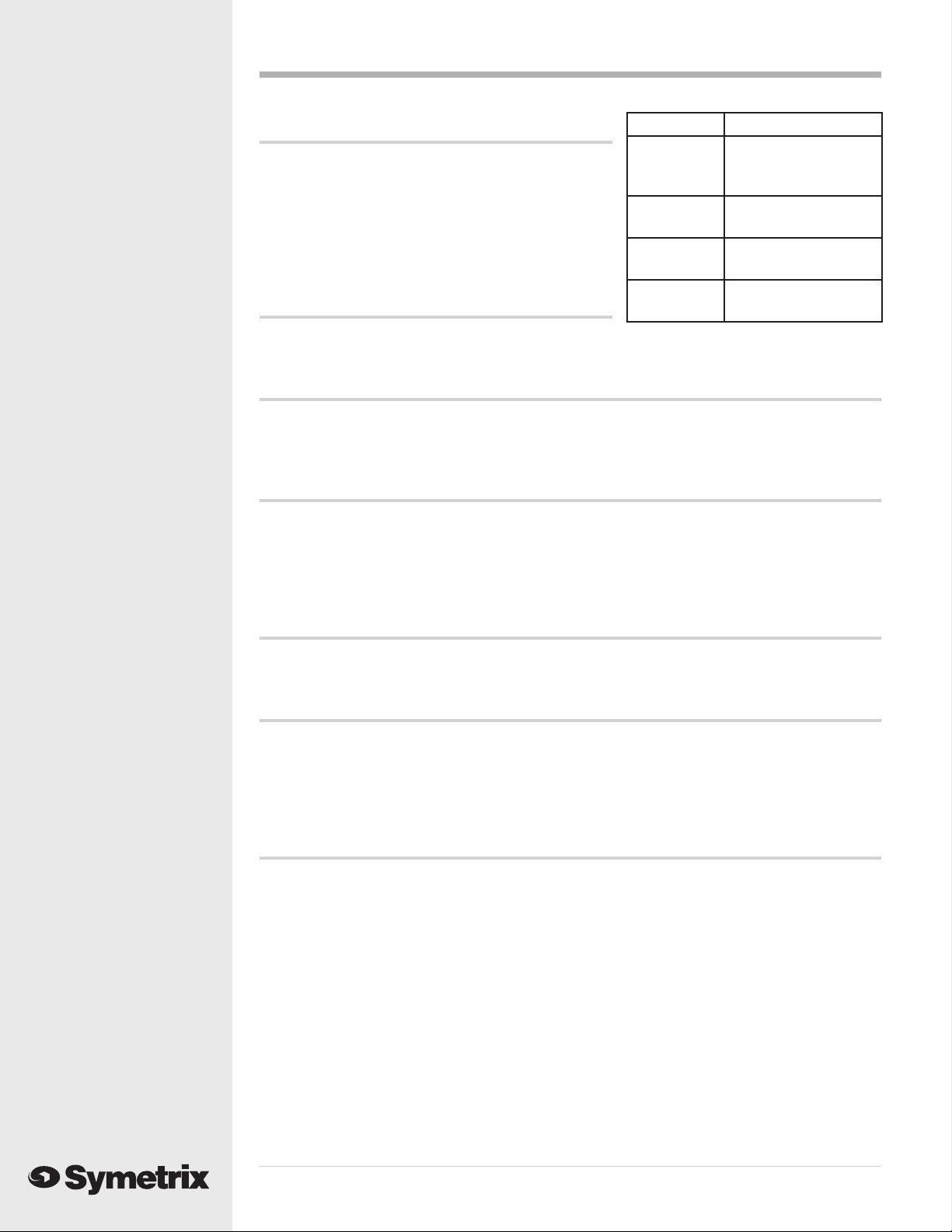
Rear Panel Setting
Output Connect to input of
console, tape recorder,
etc.
Line Input Connect line-level
source here.
Mic Input Connect microphone
here
Phantom
Power
Depress if mic requires
phatntom powering.
Downward Expander Settings
Use the downward expander to reduce room noise and/or mouth noises. Set the THRESHOLD control
to allow low level speech sounds to pass while still blocking the room sound.
Compressor Settings
Use the threshold control to vary the amount of gain reduction, as indicated on the compressor’s
gain-reduction display. Generally, 3 to 6 dB is suffi cient, unless you are using a low compression
ratio (below 2:1), or you want a special effect. Pick a ratio suited to the task at hand: low ratios and
low thresholds for unobtrusive level control, medium ratios for overall level control and con sis ten cy, high ratios (> 8:1) for limiting or in-your-face sorts of sounds.
Equalizer Settings
The settings given will work well with male voices. For women, the low-EQ range shifts up to 200
or 300Hz, the mid-EQ range shifts up to 3-5 kHz.
If you are using a microphone that exhibits proximity effect when you close-talk it, then you’ll
probably need to reduce (cut) the bass (low) response somewhat. 3-6 dB should be fi ne (don’t do
this if you want a big, ballsy sound). A bit of mid-EQ will help make voices cut and seem loud. The
high-EQ adds brightness and intimacy.
If you are using a microphone that has no proximity effect (like the ElectroVoice RE-20), then
you’ll probably need to increase (boost) the bass response somewhat. 3 to 6 dB should do the job.
The same mid- and high- EQ recommendations given previously still apply. A thorough discussion
of equalization may be found in Chapter 6.
528E
4
Page 7

Output Settings
For many applications, setting the output GAIN control at 0 dB (12:00 o’clock) works fi ne. If you
are adding a bunch of EQ (which tends to cause an overall level increase), then you may need to
decrease the GAIN setting. On the other hand, if you are using a fair amount of com pres sion, you
may need to add some gain to compensate for the level lost in compression. Pick a setting that gives
you enough signal downstream, yet still keeps the CLIP LED from illuminating. The output display
is peak re spond ing, so you can’t quite set levels as if it were a VU meter.
The output CLIP LED monitors both the equalizer and the output stage. Large amounts of boost and/
or high signal levels can cause CLIP in di ca tions. If this occurs, lower the signal level via the GAIN
control. It is also possible for the output stage to clip if a processor, inserted via the output stage
access jacks, is con trib ut ing gain to the overall signal path. In this case, either lower the gain of the
insert processor or reduce the setting of the GAIN control.
528E
5
Page 8

Mic Preamp
C
OM
D
M
30
800
8K
5
0
OUT
Y
D
BYPASS
40
0
+20
6
S
S
O
6
MIC/LINE Selects between the Mic input (switch in) and
Switch Line input (switch out).
-15 dB PAD Inserts 15 dB pad for strong mic signals.
Switch
MIC GAIN Sets the gain of the mic preamp for best com pro -
mise between signal-to-noise ratio and head room.
CLIP LED Monitors inputs (mic and line) for clipping.
Illuminates 3 dB below the actual clip point.
PHANTOM Illuminates when 48V phantom power is present at
the microphone input connector. LED The phantom
power switch is located on the rear panel.
DE-Esser
FREQUENCY Sets the rolloff (cutoff) frequency of
the de-esser.
THRESHOLD Sets the threshold level for the de-esser.
Signals above this level cause de-esser
action, signals below do not.
Chapter 4Front Panel Overview
MI
-15 PA
NOR
1
PHANT
IN/OUT Switch Hard-wire bypasses the de-esser. The
de-esser is active when this switch is in.
LED Display Indicates the amount of de-esser
activity at any instant in time.
FREQUENC
THRESHOL
Downward Expander / Compressor
EXP THRESH Sets the threshold level
for the downward
expander. Signals below
this threshold are
downward ex pand ed
(reduced in level).
COMP THRESH Sets the threshold level
for the compressor.
Signals above this
threshold cause gain
reduction in the
compressor.
COMP RATIO Sets the compression ratio of the compressor.
EXP/COMP Defeats the downward expander / compressor. This is not a hard-wire bypass.
IN/OUT Switch
201
EXP THRE
MP THRE
201
MP RATI
DOWNWARD Indicates the amount of downward expander activity (gain reduction) at any
EXPANDER instant in time.
LED Display
COMPRESSOR Indicates the amount of compressor activity (gain reduction) at any instant in
LED Display time.
528E
6
Page 9

Parametric EQ Low
15
Q
Y
H
T
15
Y
H
T
Q
15
0
)
R
15
Q
H
T
FREQUENCY Varies the center fre quen cy of the
low-frequency equalizer from
16Hz to 500 Hz.
BANDWIDTH Varies the bandwidth of the low-
frequency equalizer from 0.3 to 4
octaves. (Q=4.8 to 0.27).
CUT/BOOST Sets the degree of boost or cut;
±15 dB.
Parametric EQ Mid
FREQUENCY Varies the center frequency
of the mid-fre quen cy eq from
160 Hz to 6300 Hz.
BANDWIDTH Varies the bandwidth of the
mid-fre quen cy eq from 0.3
to 4 oc taves. (Q=4.8 to 0.27).
CUT/BOOST Sets the degree of boost or
cut; ±15 dB.
Parametric EQ High
FREQUENCY Varies the center fre quen cy
of the equalizer from
680 Hz to 22 kHz.
FREQUENC
FREQUENC
IGH E
LOW E
ANDWIDT
MID E
ANDWIDT
CUT/BOOS
CUT/BOOS
-2
BANDWIDTH Varies the bandwidth of the
high-frequency equalizer
from 0.3 to 4 oc taves.
(Q=4.8 to 0.27).
CUT/BOOST Sets the degree of boost or
cut; ±15 dB.
IN/OUT Switch Hard-wire bypasses the
entire equalizer.
ANDWIDT
CUT/BOOS
Output Section
GAIN Sets the overall gain of the 528E’s output
over a ±15 dB range. Note: the actual
ad just ment point is in the expander/
com pres sor's VCA, which is pre-EQ.
V
OICE Inserts speech waveform asym me try
SYMMETRY correction into the signal path.
UTPUT LED Indicates the peak output level of the
O
528E relative to the balanced output.
0 VU Display on the display cor re sponds
to +4dBu at the balanced output. For
unbalanced applications, the actual output
level is 6 dB lower than that shown by the
display.
Note
If the internal mic-level output switch has been de pressed, the output level is
-40 dBu when the display indicates 0 VU.
POWER LED Indicates the presence of AC power.
-2
-
GAIN (dB
POWE
528E
7
Page 10

Rear Panel Overview Chapter 5
UM
QU
Y
CE
R
O
S.
UT
E
UTTPUT
D
R
UTTPUT
D
N
R
N
UT
UT
15 WATTS MAXIM
MANUFACTURED IN THE USA B
THIS UNIT CONTAINS N
ER SERVICEABLE PART
BALAN
POWE
FABRI
SE RI AL NUM BER Please note the serial number for future reference. Should your 528E ever require
service, Symetrix Customer Service will need this information in order to process
your repair request.
AC POWER INPUT IEC-power connector. Connect only to appropriate AC power source. Refer to
rear-panel marking for correct AC source voltage.
ARATION
OUTPUT STAGE
BALANCED XLR-male. Balanced, line-level
OUTPUT output. This output may be
converted to mic-level via an
internal switch. Refer to
Appendix C.
UNBALANCED TRS phone jack (wired for
OUTPUT unbalanced operation) This is the
unbalanced, line-level output of
the 528E. This jack is unaffected
by the internal switch (see
preceding paragraph).
BALANCED OUTP
TPUT STAG
NBALANCE
INP
OUTPUT TRS phone jack (wired for un bal anced operation). This is the input to the output
STAGE stage and in ter rupts the signal coming from the remainder of the 528E.
INPUT
EQUALIZER
OUTPUT TRS phone jack (wired unbalanced). This is the
output of the equal iz er. This jack does not interrupt
the signal fl ow to the 528E’s output stage.
INPUT TRS phone jack (wired unbalanced). This is the
input to the equalizer. This jack interrupts the
signal from the Expander/Com pres sor.
EXPANDER/COMPRESSOR
OUTPUT TRS phone jack (wired unbalanced).
This is the output of the Ex pand er/
Compressor. This jack does not
interrupt the signal fl ow to the 528E’s
equalizer.
SIDECHAIN TRS phone jack wired as an insert jack
(Tip=return, Ring=send). Use this jack
528E
to access the compressor/expander’s
sidechain.
XPANDER/COMPRESSO
TP
EQUALIZE
IDECHAI
TIP=RETUR
RING=SEN
INP
INP
8
Page 11

UT
UT
SS
UT
E
UT
UT
SS
OM
R
8V
INPUT TRS phone jack (wired unbalanced). This is the input to the Ex pand er/
Compressor. This jack interrupts the signal from the De-Esser.
De-Ess
OUTPUT TRS phone jack (wired unbalanced). This is the
output of the De-Esser. This jack does not
interrupt the signal fl ow to the 528E’s Expander/
Compressor.
DE-E
INPUT TRS phone jack (wired unbalanced). This is the
input to the De-Esser. This jack interrupts the
signal from the Mic/Line inputs.
Preamp
LINE INP
-
TAG
TP
PREAMP STAGE TRS phone jack (wired un bal anced). This is the output of the Mic/Line preamp.
OUTPUT This jack does not interrupt the signal flow to the 528E’s De-Esser.
LINE INPUT XLR Connector. 10-kilohm balanced bridging line input intended for signals
ranging from -10 dBu to +4 dBu.
MIC INPUT XLR connector. Balanced input suitable for low-impedance microphones. 48V
phantom powering avail able.
MIC INP
TP
INP
PHANT
POWE
+4
BYPA
PHANTOM POWER Pushbutton switch enabling Phantom Power on Mic Input.
528E
9
Page 12

Voice Processing Tu to ri al
Basics
The Symetrix 528E Voice Processor com bines Symetrix’ program controlled interactive dynamic
range processing technique with a three-band parametric equalizer. This com bi na tion of processors is similar to a voiceover or vocal signal processing chain as used in a recording or voiceover
studio. “Program controlled” means the 528E’s dynamic range processor section analyzes in com ing
signals, then adjusts its release time to match the transient characteristics of those signals.
This chapter of the manual contains a tutorial on the basics of dynamic range pro cess ing and
equalization: the two key ingredients in the 528E. The tutorial information is intended to provide a
background for the information found in the remainder of this manual.
Dynamic Range Pro cess ing
Dynamic range processors are used to fi t wide-range signals into narrow-range transmission or storage channels. The dynamic range of acous ti cal signals found in real life usually far exceeds our capacity to store or transmit them. Con front ed with this dilemma, audio engineers usually reach for a
compressor/limiter or down ward expander as a means to fi t two-pound signals into one-pound bags.
Compressor/limiters respond quickly to tran sients, and gently to normal speech level changes which
keeps overall levels in check. The downward expander’s operation is the inverse of the com pres sor/
limiter which prevents “pump ing” and “breathing” even when high ratio compression is necessary. Because the com pres sor/limiter and the downward expander are interactive, the 528E always
responds ap pro pri ate ly, while pro vid ing automatic control over a wide range of input levels.
Chapter 6
Strictly speaking, the terms compressor and limiter refer to two different devices. Oftentimes the
two are combined into a single device called a com pres sor/limiter. Com pres sor/limiters usually
perform as either a com pres sor or a limiter, but not both at once. Functionally, a compressor/limiter
is a device that lets the user defi ne, or predetermine, the maximum level of an audio signal.
Expanders and gates are the functional opposites of com pres sors and limiters. Compressors con tin u ous ly reduce the dynamic range of signals that are above threshold, while expanders con tin u ous ly
increase the dynamic range of signals that are below threshold. Limiters can be thought of as very
high ratio compressors, and gates can be thought of as very high ratio ex pand ers.
In addition to their roles as remedial signal processors, compressors also have a creative role.
You can use a compressor to increase the apparent sustain of a guitar, increase apparent loudness,
improve the consistency of a bass by removing or reducing level changes, and many other things.
Generally speaking, the settings for these applications are somewhat extreme, so experimentation is
the name of the game.
Defi ning Dynamic Range
To begin a discussion of dynamic range processors it’s necessary to have a working defi nition of
dynamic range. The term is really self-descriptive, but has two distinctly different uses:
1. To describe the actual range of signal fl uctuations that are going through the equipment.
2. To defi ne the maximum allowable range of signal fl uctuations that can be put through the
equipment.
The usual unit of measure for audio signals is the decibel (dB).
Dynamic Range as a Specifi cation
The maximum usable range of operation for a particular circuit or piece of gear is the distance in dB
between the noise fl oor and the maximum output level. In this context, dynamic range is used as an
equipment specifi cation.
Noise fl oor is defi ned as the lower limit of a circuit’s operating level, and is a function of its self-
528E
generated electrical noise. Very noisy circuits have a high noise fl oor, quiet circuits have a low noise
fl oor. All circuits have a noise fl oor, unless they are operating at -460 degrees Fahrenheit (absolute
10
Page 13

zero). The maximum output level of a circuit is the upper limit of the operating level, and is the
level at which clipping begins and is a function of the internal power supply voltage. To put levels
in perspective they must be referenced to some nominal operating level, like 0 dBm. That’s why
noise specs are stated as negative numbers.
In the case of the 528E, noise is referred to the input, and stated as equivalent input noise (EIN).
The noise spec i fi ca tion is given this way because the gain of the 528E’s input stage is variable, so
the actual signal-to-noise performance of the unit becomes a function of how much gain is used in
the preamp. To fi nd the signal-to-noise ratio at 0 dBm output, algebraically add the preamp gain to
the EIN.1
Since maximum output level is usually greater than 0 dBm, it’s stated as plus something. The
528E’s maximum output level is +18 dBm into a 600-ohm balanced load, which is 18 dB above 0
dBm. The difference between the noise fl oor and the onset of clipping is the dynamic range. To fi nd
the 528E’s dynamic range with 50 dB preamp gain, subtract -89 from 18. The result (113 dB) is the
dynamic range.
Dynamic Range of Sounds and Signals
The other defi nition of dynamic range describes actual level changes, or the range over which
signals fl uctuate. The signals under discussion here are electrical representations of sounds, so it
follows that sound has dynamic range. The dynamic range of the human voice, from a whisper to a
shout, is well over 100 dB. Thus, the microphone converts the sound pressure of a voice going from
a whisper to a shout into an electrical output signal having the same dynamic range.
Why Dynamic Range Processors are Necessary
For signals to stay below distortion and above noise, their actual dynamic range must be kept within
the specifi ed dynamic range of the circuits through which those signals fl ow. Unfortunately, the
actual dynamic range of real world signals often exceeds the available dynamic range of even the
best equipment.
For example, the dynamic range of the best analog tape recorders is around 80 dB, while digital re cord ers top out at around 96 dB. As good as these machines are, there’s still not quite enough room
for very wide dynamic range signals. In order to maintain a 60 dB signal-to-noise ratio (to keep the
signals 60 dB above the noise fl oor), the dynamic range of signals stored on the analog tape machine would have to be restricted by 20 dB, while the digital recorder would be restricted by 36 dB.
A compressor or limiter is often used to reduce dynamic range by setting an upper limit on the
larger signals. In some cases, it’s better to put processing to work on the lower end of the dynamic
range than on the upper end. In other words, instead of reducing the amount of change at the upper end of the dynamic range with a compressor or limiter, increasing the amount of change at the
lower end of the dynamic range with a downward expander or gate.
Compressors are to Downward Expanders as Limiters are to Gates
Compressors reduce the dynamic range of their output whenever the input signal is above thresh old,
while downward expanders increase the dynamic range of their output whenever the input signal is
below threshold.
Compressors, limiters, expanders, and gates increase or decrease signal levels by some ratio.
Compressors usually have an adjustable ratio, the ratio of the input level to the output level, which
is generally user-adjustable. A compressor operating with a 2:1 ratio allows only a 1 dB increase in
output level for every 2 dB increase in input level.
Limiters usually have a nonadjustable ratio that is very high (greater than 10:1). At 10:1, the limiter
allows only a 1 dB increase in the output level for every 10 dB increase in the input level. Limiters
can be thought of as high ratio, high threshold compressors. They are intended to “stay out of the
way” until the level goes above threshold. However, above threshold their action is very defi nite.
528E
11
Page 14

The Threshold Concept
The threshold is the level at which a dynamic range processor’s activity begins. In operation, the
dynamic range processor’s sensing circuitry constantly “looks at” the incoming signal and com pares it to a reference level, which is called the threshold level. In practice that reference level is
set by the operator via the threshold control. Remember, compressors and limiters respond when
signals at the input are above threshold, while downward expanders and gates respond only when
signals at the input are lower than the defi ned threshold.
The VCA - Voltage Controlled Amplifi er
The action of any dynamic range processor depends on some method of changing the gain based
on some external signal. Typically this takes the form of a special sort of amplifi er whose gain is
controlled by a DC voltage. That part of the circuit is called a voltage controlled amplifi er, or VCA.
Inside the 528E a separate buffered audio signal is sent to a group of circuits that comprise the
detector (envelope follower to you synthesists). The detector circuits turn the AC audio signal into a
DC control voltage, which is sent to the VCA under the direction of the front panel controls.
Linear vs. Downward Expanders
Expander operation is easily misunderstood unless it’s remembered that what’s being expanded is
the dynamics, or changes, of signals passing through the circuit. Expanders come in two very different types: linear, and downward.
Linear expanders increase the dynamic range of all signals, no matter what their actual level. The
linear expander simply makes all changes greater by some ratio, which is sometimes user ad just able. In the real world, linear expanders aren’t too practical because clipping occurs when signals
just below maximum output level are expanded.
For instance, an unprocessed signal 3 dB below clipping that increases 2 dB won’t distort, because
it’s still 1 dB below maximum. But if that same signal is passed through an expander operating at a
1:2 ratio, the same 2 dB change at the expander’s input becomes a 4 dB change at its output. However, that signal would be 1 dB over maximum, causing distortion. Linear expanders must be used
with care, because very few systems have enough headroom to handle the upward dynamic range
increase they produce.
The kind of processor most commonly called an expander is really a downward expander, because
it only affects signals below threshold. This gives the operator control over the expander’s ac tiv i ties, allowing it to be used to expand the usable dynamic range of the system without running out of
headroom.
Note: in the interests of clarity and brevity, the term expander will be defi ned as a downward expander from this point forward in this manual.
How Expanders Increase Usable Dynamic Range
The lower limit restriction of a system is the noise fl oor, which is usually well below the 528E’s
lowest expander threshold (-50 dBu). It’s important to keep in mind that while the signal levels may
change greatly, the noise usually doesn’t change very much. The action of the expander increases
the dynamic range of all signals below threshold. This action increases the apparent loudness of
signals, while decreasing the apparent loudness of the noise.
For example, an expander operating at a ratio of 1:2 will cause an input signal that falls 10 dB
below threshold to fall 20 dB at its output. The downward action of the expander reduces the noise
fl oor by the same ratio applied to the signal. Since the relationship between the signal and the noise
stays the same, the noise is reduced 20 dB by the action of expander, which is responding to a 10
dB drop in the signal with its 1:2 ratio.
528E
12
Page 15

De-essers
A de-esser is another type of dynamic range controller that’s specially designed to regulate high
frequency content. The technique was originally developed for motion picture dialogue recording,
when it was discovered that speech sounded more natural and pleasing when the accentuation of
sibilants was reduced. By sensing and limiting certain selected frequencies, the de-esser is in tend ed
to provide more specifi c control over some of the higher frequency vocal sounds that tend to become overemphasized especially when the talker is close-miked.
Many sibilant vocal sounds like “s,” “sh,” and “t” are very diffi cult to reproduce electronically, because they contain a large percentage of very high frequency harmonics. But because these sounds
are essential to the intelligibility of speech, they cannot be simply removed with equal iza tion. In
fact, to help maintain articulation many sound engineers boost the higher frequencies of the vocal
spectrum (3 kHz to 8 kHz), and/or use microphones with “presence curves.” However, in certain
individuals sibilant sounds are already over-accentuated, and any kind of high frequency boost only
exacerbates the situation.
The 528E’s de-esser controls excessive sibilant and fricative vocal sounds, which can often be as
much as 12 dB louder than the rest of the spectrum. It’s activity is similar to a frequency conscious
compressor/limiter (with an equalizer boosting the high frequencies in the sidechain). Unlike a
compressor/limiter however, the de-esser operates only on the frequencies selected and above.
Unlike an equalizer, the de-esser can reduce the offending sounds without sac ri fi c ing intelligibility,
because it operates dynamically, removing only sounds that are disproportionately loud, and only
those that fall within the operator-selected control range.
De-essers usually include controls that allow the operator to determine which frequencies are controlled, and how much those frequencies are actually attenuated. The 528E’s de-esser controls are
frequency, which is variable from 800 Hz to 8 kHz, and threshold, which may be set from 0 dB to
-30 dB. In other words, the 528E’s de-esser will attenuate selected frequencies between 800 Hz and
8 kHz as much as 20 dB.
Sidechain Processing
The sidechain is a patch point in the control circuit of a dynamic range processor, which provides
access to the part of the circuitry that tells the VCA what to do. The 528E’s sidechain routes through
a rear panel TRS jack that allows the control signal to be processed outside the unit (see Figure 7-6
for specifi c hookup information).
Refer to the block diagram in Figure 7-1. Notice the sidechain connections that come from the
compressor/limiter/expander section. They allow access to the audio input of the control circuit (a
fancy envelope follower by any other name) for the dynamic range processor. This control signal
is derived from, but kept totally separate from, the audio signal path. That means the control signal
can be processed outside the 528E without actually processing the signal that’s going through the
VCA (the audio signal itself). This presents some very interesting possibilities for changing or improving the operation of the dynamic range processor.
The best use of the sidechain connections is to make the action of the 528E’s dynamics processor
frequency dependent, that is, to make it respond more (or less) to certain frequencies. Because the
audio signal and the control signal remain completely separate (even while the control circuit tells
the VCA whether to turn the gain up or down), you can equalize the sidechain without changing the
EQ in the main audio path.
Removing unwanted frequencies from the control signal before it actually reaches the VCA prevents those frequencies from being used to create gain changes. Applications utilizing the sidechain
may be found in Chapter 8.
528E
13
Page 16

Equalization
Equalization is one of the most powerful tools available to the audio engineer. It is, quite possibly,
the fi rst signal modifi cation device that most people experience (aside from the volume control).
This experience takes the form of using the tone controls found on most consumer audio equip ment. Even in this primitive form, simple tone controls can shape and alter a sound, giving us
pleasure or pain, evoking emotion, or simply enhancing our listening pleasure.
The parametric EQ in the 528E provides both creative and corrective frequency shaping - it can be
used to create a more pleasing sound, and to correct frequency response problems. The equalizer
has a symmetrical ±15 dB boost/cut response.
The term “parametric” simply refers to the fact that the primary operating parameters of the equalizer may be altered by the user. The user adjustable parameters are:
• center frequency (or fc, expressed in Hz),
• bandwidth (sometimes called “Q,” or selectivity, expressed in octaves), and
• the amount of cut or boost (expressed indB).
These terms are defi ned as follows:
1. Center Frequency is defi ned as the frequency (in Hz) of the middle of the bell shaped response
curve formed by a fi lter.
2. Bandwidth is the width of the bell shaped curve, measured between its -3 dB points. The
measure of bandwidth in audio equalizers is usually given in octaves or parts of an octave.
3. Cut or Boost is given in dB, at the center frequency.
Equalization Tutorial
Equalization is nothing more than selectively (or not) amplifying a signal based on frequency. Since
audio signals consist of combinations of fundamental signals and their harmonics, changing the tonality or the spectral balance of a signal involves nothing more than altering the relationship of the
fundamental to its harmonics, and of the harmonics to themselves. Each harmonic is re spon si ble for
one aspect of the audible character of a signal; knowing these relationships allows you to quickly
zero-in on the correct frequency range of the signal and apply boost or cut to enhance or correct
what you are hearing.
The audio spectrum has several critical portions that are responsible for our perceptions of sounds
that we hear:
Range Frequencies Musical Location
Very Low Bass 16-64 Hz 1st and 2nd octaves.
Bass 64-256 Hz 3rd and 4th octaves.
Midrange 256-2048 Hz 5th, 6th, and 7th octaves.
“Lisping” Quality 3000 Hz Between the 7th and 8th octaves.
Presence Range 4750-5000 Hz Between the 8th and 9th octaves.
2
Brilliance 6500-16 kHz Part of the 9th through the 10th octave.
Power and Fullness
In the very low bass region lies the threshold of feeling, where the lowest sounds, like wind, room
effects, and distant thunder, are felt, rather than heard. In the upper half of the fi rst octave of this
range, research has shown that the fundamentals of piano, organ and even the harp reach well into
this range. Harvey Fletcher (of Fletcher-Munson fame) charted the sensitivity of the ear for various
528E
parts of the spectrum at levels that are lower than those of reality. Fletcher’s compensation curves
(the well known Fletcher-Munson curves) show that for equal loudness in this range at lower
14
Page 17

recorded and reproduced levels shows requirements for tre men dous boosts, on the order of 10 to 30
dB. Aside from the subjective effects of this range, the ability to control unwanted sounds in this
range is equally important to subdue stage rumble and outside traffi c noise (especially im por tant
where there are subways beneath buildings!). Overemphasis caused by close cardioid mi cro phone
placement can cause muddiness in the overall sound; attenuating (cutting) the very-low-bass region
can greatly improve overall clarity.
Rhythm and Musical Foundation
In the bass region, most of the low, grave tones of the drum and piano can be found. Here we can
also fi nd the fundamentals of the rhythm section, as well as the foundation of all musical structure.
It was Leopold Stowkowski who said “If I had a thousand bass viols I could use them all!” This is
not as extreme as it may sound. A bass viol, even though it is reinforced by its sounding board, generally plays single notes and possesses little dynamic range. In a large orchestra, as many as eight
bass viols may be used. A total of 1000 bass viols in this case would only give an additional 21 dB
of level, which is not an inordinate amount given a glance at Mr. Fletcher’s equal loudness curves.
Pay attention to this range because the overall musical balance of your program can be controlled
by equalizing or attenuating the 100 Hz range.
Telephone Quality
The ear is reasonably sensitive in the midrange frequencies, and sound restricted to this range has
a telephone-like quality (which is generally why telephone-quality frequency response covers the
300-3 kHz range).
If you make the 6th octave (500-1024 Hz) louder with respect to the other octaves, the subjective
result is a horn-like quality. If you emphasize the 7th octave (1000-2000 Hz), the effect is one of
tinniness.
The fundamental tones in most music lie equally above and below middle C (261 Hz), from 128 to
512 Hz. As most instruments are rich in the fi rst overtones, the majority of sound energy is found up
to the 2.5 kHz range. Music editors and others engaged in listening to music over long periods fi nd
that listening fatigue can be reduced by attenuating the 5th, 6th, and 7th octaves by about 5 dB.
Lisping Quality
The 3 kHz range delivers a generous stimulus to the ear. At very loud levels the region of greatest
ear sensitivity shifts downward from 5 kHz; this is why many “PA” speakers have broad peaks in
this region. A char ac ter is tic of low-level signals peaked at 3 kHz is a “lisping” quality, and the total
inability to distinguish labial sounds such as m, b, and v.
In wide-range lower level systems, a peak in the 3 kHz region has a masking effect on important
rec og ni tion sounds, and on others which lie above 4 kHz. Brilliance and clarity are lost and without
attenuation of this region, an unconscious strain with increasing fatigue is felt according to the
amount of 3 kHz boost.
Presence Range
The usual band affecting clarity in male speech is 3000 to 6000 Hz. In a woman’s voice, the fun da men tals are roughly an octave higher than a man’s, and a woman’s range of consonant clarity lies
between 5000 and 8000 Hz (the high-end of this range approaches a region of hearing in sen si tiv i ty
in humans). Furthermore, the total range of a woman’s voice is about half that of a mans, stim u lat ing fewer hearing nerves, and for this reason, is consequently still weaker upon reception.
Wide range sounds, especially those of singing voices, have fundamentals with harmonics in the 5
kHz region of good ear sensitivity. Voices that are powerful or rich with harmonics at 5 kHz sound
especially pleasing, clear and full. Male opera singers are particularly favored with 5 kHz sounds,
women less so. In popular music, this range shifts downward somewhat. It follows that voices
defi cient in the 5 kHz range can be enhanced in listening value by a generous boost on the order of
5 to 8 dB at 5 kHz. A secondary benefi t of this boost is an apparent increase in level; a 6 dB rise at 5
15
528E
Page 18

kHz frequently gives an apparent increase of 3 dB to the overall signal.
Attenuating the 5 kHz range on instruments gives a “transparent” quality to the sound, providing,
of course, that the remainder of the signal is otherwise wide range. Microphones having a dip in
this region lack the “punch” or “presence” to which we (Americans) are accustomed.
Brilliance
Unvoiced consonants attributed to tooth, tongue and lip sounds are high in frequency, and reach the
10 kHz range. These frequencies account for some clarity and most brilliance, even though they
contain less than 2% of the total speech energy. This also holds true for musical instruments; especially percussion. Boosting or cutting this range affects clarity and naturalness. In speech, the 9th
and 10th octaves impart intimacy although too much emphasis can make secondary speech sounds
(lip smacking, etc.) objectionable (a good case for a expander).
Some microphones having a rise at the higher fre quen cies (especially omni microphones) benefi t
from some attenuation in this region. Those microphones having under damped diaphragms may
ring at these frequencies, causing an annoying sibilant distortion on speech. On musical forms using hand percussion, boosting this range frequently results in an astonishing and pleasing feeling of
clarity.
Conclusions
When the article containing the above excerpts was written (probably around 1963), stereo was just
becoming a commercial reality (you could still purchase mono and stereo versions of an LP and
there were still more FM stations broadcasting in mono than stereo), and as many mixers contained
rotary mix pots as those that used slide pots. The value of individual channel equal iza tion was
known, but it was both technologically and fi nancially prohibitive. The article concludes thusly:
“With the advent of stereo and three-channel recording, nearly three times the equipment, with
more elaboration, seems indicated, and expansion of console area in the horizontal plane offers the
only direction in which to proceed. But a single engineer has arms only so long.”
How times have changed!
Using the Parametric Equalizer
Great care must be exercised when using equalization. The following paragraphs give some general
hints and pre cau tions for using the 528E’s parametric equalizer (or any other equalizer, for that
matter).
Beware of Distortion and Noise
When a frequency or group of frequencies are boosted, the overall operating level is boosted as
well. For example, 12 dB of boost (no matter what the frequency) increases the 528E’s output level
12 dB (at that frequency). This kind of boost reduces headroom by 12 dB in every circuit from the
528E’s own line driver to the last device in the signal chain (transmitter, tape machine, or what
have you). Unless signal levels are very low to begin with, the 528E’s output gain will have to be
reduced to compensate for increased levels whenever the equalizer is used for boost.
The Clip LED in the Output LED meter monitors levels in the equalizer as well as at the output of
the 528E. If the Clip LED glows, try switching the equalizer to Bypass. If the LED still glows, reduce the setting of the Output Gain control. If switching the equalizer to Bypass eliminates the clip
indication, then the input level must be reduced via the Mic Gain control or by lowering the level of
the line input.
On the other hand, if the levels within the 528E are too low to start with, using the equalizer for
boost may increase noise to unacceptable levels.
528E
If levels are too low, increase the preamp gain (or the output level of the device feeding the line
input).
16
Page 19

Know What You Are Listening To
Low frequency boost may increase the level of some frequencies that cannot be heard, for one reason or another. Many high quality microphones are capable of generating substantial output at very
low frequencies (below 50 Hz) which cannot be adequately reproduced by most monitor speakers
or headphones. Be aware that the true effects of low frequency boost may not be audible, and may
actually result in a “muddy” or distorted sound.
Use Wide Peaks, Narrow Dips
In general, the human ear prefers wide bandwidth peaks and narrow bandwidth dips. Boosting a
narrow bandwidth produces a sound usually perceived as “offensive,” while boosting wider bandwidths (.7 octave or greater) usually results in a sound deemed “musical.” It has also been observed
that very few people will notice anything’s missing when a narrow bandwidth (.3 octave or less) is
cut, even when it’s cut as much as 30 dB. But, cut a wide bandwidth and the resulting sound quality is often called “empty.”
Tuning the EQ/Notch Filter
To “tune” the equalizer, use full boost. For both boost and cut, the 528E’s parametric equalizer
is intended to be put to work on specifi c frequencies. To fi nd a particular frequency “by ear” (the
method used by everyone who doesn’t have a real-time analyzer), turn the cut/boost control all the
way up to +15 dB (be very careful of feedback if you are monitoring on a loudspeaker!). Set the
bandwidth for about .3 octave (max CCW). Tune the frequency control until you distinctly hear the
part of the sound you wish to control. Then, adjust the cut/boost control for the appropriate amount
of change, and readjust the bandwidth control if necessary.
Equalizing for Speech
In broadcast, equalizers are often used to create a sonic personality for the station’s on-air talent.
In production applications, it is practical to write down each person’s settings. In broadcast ap pli ca tions (on-air), most stations try to fi nd a single composite setting that works for all of their on-air
talent. If your station’s on-air talent is comprised of both men and women then fi nding a single,
compromise setting becomes more diffi cult. A possibly more workable solution might be to use a
single-D3 microphone (so it has proximity effect) and to vary the working distance to alter the lowfrequency response somewhat.
Some general thoughts on speech equalization:
1. Try to use wider bandwidths. Narrower bandwidths (1/2 octave and less) are less audible
(harder to hear) and are generally only useful for remedial work. Broader bandwidths are
less obnoxious, more pleasing sounding, and easier to work with (especially if you’re
boosting a range of frequencies).
2. Try to avoid massive amounts of boost or cut. If you’re only trying to impart a fl avor (like
sprinkling salt and pepper on a meal), then 6-8 dB of boost or cut should be all that you
need.
3. A wide bandwidth cut is equivalent to a boost at the frequencies surrounding the cut.
4. A quick way to fi gure out what’s going on is to set the level of one band of the equalizer
to full boost (+15 dB), then switch to the frequency control and vary the frequency of that
band of the equalizer while listening to program material fed through the unit. This usually
makes quick work out of fi nding the region that you want to work on. Now reduce the level
setting to something tasteful.
A common problem when trying to set an equalizer for someone’s voice is converting the de scrip tive adjectives that people use in describing the character of a voice into the numbers that make
equalizers happy. The following table list some commonly used adjectives and their corresponding
fre quen cy ranges.
528E
17
Page 20

Range Description (women) Range Description (men)
100-250 Hz Fullness 75-200 Hz “Balls”, rumble, heaviness
250-400 Hz Bassiness, bigness 200-300 Hz Bassiness, bigness
400-600 Hz Warmth 400-600 Hz Chesty
600-1 kHz Volume 600-1 kHz Volume
2 kHz-4 kHz Clarity 2 kHz-4 kHz Clarity
3 kHz - 5 kHz Nasal, yell, presence 3 kHz-5kHz Nasal, yell, presence
5 kHz-8 kHz Enunciation, intimacy 5 kHz-8 kHz Enunciation, intimacy
10 kHz up Air, mouth noises 10 kHz up Air, mouth noises
To tailor your station’s announce sound, begin with an idea of what general sound you want. Since
you only have three general locations that you can equalize at, you’ll need to begin with the aspects
of your sound that are most im por tant. The choice of microphone is very important, since every
microphone imparts its own equalization to any sound that it hears. If you want a large, “ballsy”
sound, you ought to think about single-D cardioid microphones such as those made by AKG, Shure,
Neumann, Sennheiser, and EV (like the RE38N/D or ND series) or a ribbon mi cro phone such as
the RCA 77DX. The built-in bass boost caused by close talking a single-D mi cro phone (proximity
effect) can be tailored or tamed with careful equalization, which also reduces room rumble at the
same time. Last, since the proximity effect increases with decreasing source-mi cro phone distance, a
skilled user can substantially change their sound simply by moving in or out from the mi cro phone.
If clarity is your goal, then a variable-D4 microphone such as the EV RE-20, RE-27 or RE-18 or
an om ni di rec tion al type such as the EV RE50 or AKG414 (with the pattern set to omni) is a good
choice as these types do not emphasize the bass frequencies when you close-talk them. On the
negative side, any room rumble present with the microphone will be boosted along with the voice if
you try to equalize at the lower frequencies.
Next, add or remove low frequencies in the 100-300 Hz range until you get a weight or fullness
that is pleasing. Next add midrange boost in the 2.5 kHz to 5 kHz range to add punch and pres ence
(experiment with the bandwidth control!), and fi nally add or remove fre quen cies in the 10000+ Hz
range to get the sense of brilliance that you want.
The chart on the next page shows the re la tion ships of many different instruments, and a piano keyboard along with the frequencies involved.
Notes
1
Equivalent input noise (EIN) is a method of modeling the noise performance of a preamp as the
signal level of an equivalent noise source connected to the input of a noise less pream pli fi er. The
thermal noise of a 150-ohm resistor is about -133dBV; this rep re sents the theoretical best case.
2
The majority of the material in Section 2.2 is taken from “Equalizing for Spectral Character,”
Langevin Corporation, 1966 Catalog.
3
A single-D microphone is a directional microphone having its rear-entry port(s) spaced at a single
distance from the diaphragm. Single-D mi cro phones are always characterized by proximity effect, a
rise in the bass response at short working distances.
4
A variable-D cardioid microphone has multiple rear entry ports spaced at varying distances from
its diaphragm. Variable-D microphones have little or no proximity effect. Variable-D is a trademark
of Electro-Voice Inc.
528E
18
Page 21

OLO
21
83
CC
PI
TS
N
E
M
TE
U
FL
OE
B
O
ET
N
I
AR
L
C
PET
M
RU
T
RN
O
H
NCH
E
R
F
.
9393.20
8372.00
7902.20
7040.00
6272.00
5587.60
5274.00
4698.60
4186.00
3951.10
3520.00
3136.00
2793.80
2637.00
2349.30
2093.00
1975.50
1760.00
1568.00
1396.90
1318.50
1174.70
1046.50
987.77
880.00
783.99
698.46
659.26
587.33
523.25
493.88
440.00
392.00
349.43
329.63
293.66
261.63
246.94
220.00
196.00
174.61
164.81
146.83
130.81
123.47
110.00
98.00
87.31
82.41
73.42
65.41
61.74
55.00
49.00
43.65
41.20
36.71
32.70
30.87
27.50
24.50
15804.40
14080.00
12544.00
11175.20
10548.00
LE
B
E
R
T
SS
BA
528E
9
B
9
A
9
G
9
F
9
E
9
D
9
C
8
B
8
A
8
G
8
F
8
E
8
D
8
C
7
B
7
A
7
G
7
F
7
E
7
D
7
C
6
B
6
A
6
G
6
F
6
E
6
D
6
C
5
B
N
VIOLI
O
RAN
A
SOP
VIOL
LTO
A
ET
N
I
E
N
AR
O
L
N
B
C
M
O
R
SS
T
BA
SSOO
UBA
BA
M
DRU
ELLO
C
R
O
N
TE
E
N
O
IT
BAR
SS
BA
SS T
BA
ETTLE
K
SS V IOL
BA
TS
N
E
M
5
A
5
G
5
F
5
E
5
D
5
C
4
B
4
A
4
G
4
F
4
E
4
D
4
C
3
B
3
A
3
G
3
F
3
E
3
D
3
C
2
B
2
A
2
G
2
F
2
E
2
D
2
C
1
B
1
A
1
G
1
F
1
E
1
D
1
C
0
B
0
A
0
G
19
Page 22

Using the 528E Chapter 7
This section is intended for more advanced users. If you are a fi rst-time user, we recommend that
you start out by using the procedure found in “Fast Setup.”
Block Diagram
Figure 7-1 on the next page is the block diagram for the 528E. Please take a moment and take note
of the fol low ing:
• The equalizer and de-esser are hard-wire bypassed by their IN/OUT switch es.
• The interstage patch points use TRS jacks wired for unbalanced operation.
• The interstage patch points are half-normalled. The send jack does not break the signal fl ow.
The output level of the 528E can be set to either line level or mic level. The switch for this function
is internal to the unit. Refer to Appendix A.
Installation
The 528E may be installed freestanding or rack mounted. Rubber feet are included for freestanding
use. No special ventilation requirements are necessary. Table 7-1 lists the 528E’s re quire ments for
installation.
Installation Requirements
Mechanical One rack space (1.75 inches) required, 12.5 inches depth (including con nec tor
allowance). Rear chassis support recommended for road applications.
Electrical 105-125V ac, 12.5 Watts maximum. 210-250V ac, 50 Hz, 12.5W maximum
(export).
Connectors XLR-3 female for inputs, XLR-3 male and TRS 1/4-inch female for outputs, Pin
2 of the XLR connectors is “Hot.”
The sidechain access jack output uses a TRS jack wired as an insert jack (tip=return, ring=send).
The interstage patch points use TRS jacks with the ring and sleeve connections connected to circuit
ground. The jacks are half-normalled (only input breaks normal).
Level Setting
For optimum noise performance, correct level settings are a must, especially for microphone
sources. You should operate the 528E’s mic preamp at the highest gain possible without overload.
Extremely hot signals may require using the -15 dB pad switch.
The 528E expects line level signals to fall in the +4 dBu region. Lower signal levels are okay, but
the noise performance may suffer as there is no gain trim control for the line input.
LIP LED in the mic input section of the 528E actually monitors the output of the MIC-LINE
The C
switch. If the LED glows, and you are using the MIC input, then reduce the setting of the MIC GAIN
control until the LED no longer glows. If you are using the LINE input, reduce the level of the device driving the 528E.
The C
LIP LED in the OUTPUT LED meter monitors levels in the equalizer as well as at the output
of the 528E. If the CLIP LED glows, try switching the equalizer to BYPASS. If the LED still glows,
reduce the setting of the OUTPUT GAIN control. If switching the equalizer to BYPASS eliminates the
clip indication, then the input level must be reduced via the MIC GAIN control or by lowering the
level of the line input.
528E
20
Page 23

THRESHOLD
FREQUENCY
DE-ESS
IN/OUT
ESS
E
D
EQ
INPUT
OUTPUT
EXP/COMP
GAIN
IN/OUT
EXP/COMP
RATIO
COMP
THRES
COMP
EXP
THRES
EXPANDER/COMPRESSOR
EXTERNAL SIDECHAIN
(RING=SEND. TIP=RETURN)
R
O
ESS
R
P
COM
D
R
R
E
A
D
W
N
AN
P
W
X
O
E
D
OUTPUT STAGE
INPUT
EQ
OUTPUT
EQ
IN/OUT
REV-F
BALANCED
OUTPUT
INTERNAL
OUTPUT LEVEL
SELECT SWITCH
EQ CLIP DETECTION
H
Q
IG
E
H
OUTPUT LEVEL DISPLAY
L
E
V
E
ION
L
T
T
C
U
E
P
L
T
U
SE
O
T
P
E
U
T
M
P
T
U
U
U
H
M
T
O
OUTPUT
UNBALANCED
T
I
U
C
R
CI
T
I
U
C
R
CI
MIC
CLIP
MIC GAIN
+48V/BYPASS IN/OUT
P
AM
E
R
P
B
D
d
A
P
-15
R
OM
E
T
W
O
AN
P
H
P
SS
E
R
P
LINE
Y
L
PP
U
S
S
S
E
R
P
Figure 7-1. 528E Block Diagram
CUT/BOOST CUT/BOOST CUT/BOOST
BANDWIDTH BANDWIDTH BANDWIDTH
FREQUENCY FREQUENCY FREQUENCY
T
I
U
D
Q
E
MI
VOICE
IN/OUT
SYMMETRY
W
Q
O
E
L
OPTIONAL
POWER SWITCH
E
AG
T
S
T
U
P
T
U
O
R
E
W
O
P
Y
R
T
E
MM
Y
S
H
T
I
W
Y
L
PP
U
S
C
R
ION CI
T
C
E
RR
CO
528E
21
 Loading...