

Page 1
SymetrixSymetrix
425
Dual Compressor / Limiter
Owner’s Manual
Signal Processing at it’s Best!
Revision 2.0, 10/29/93
Part number: 530201
Subject to change at our whim, and without notice.
Copyright 1992–1993 by Symetrix Inc. All rights Reserved.
Batteries not included. Void where taxed or prohibited. Ground ain’t ground!
Page 2

Table of Contents
1. Introduction...........................................................................................1-1
1.1 About this manual...........................................................................................1-1
1.2 Operator Safety Summary..............................................................................1-2
1.2.1 Equipment Markings....................................................................................1-2
1.2.2. Terms .........................................................................................................1-2
1.3. Other Safety Information ...............................................................................1-3
2. Dynamics Processing Tutorial and Functional Basics.....................2-1
2.1 Dynamics Processing Basics..........................................................................2-1
2.1.1 Compressors and Limiters...........................................................................2-1
2.1.2 Expanders and Gates..................................................................................2-2
2.1.3 Ratio............................................................................................................2-2
2.1.4 Gain vs Output ............................................................................................2-2
2.1.5 Attack Time..................................................................................................2-2
2.1.6 Release Time ..............................................................................................2-3
2.1.7 Threshold Setting ........................................................................................2-3
2.1.8 Interpreting the Displays..............................................................................2-3
2.2 Using the Sidechain........................................................................................2-3
3. Technical Tutorial ................................................................................3-1
3.1. Matching Levels vs Matching Impedances .....................................................3-1
3.2. Signal Levels ..................................................................................................3-2
3.3. I/O Impedances ..............................................................................................3-2
3.4. Polarity Convention ........................................................................................3-2
3.5. Input and Output Connections........................................................................3-3
4. Front Panel Overview..........................................................................4-1
5. Rear Panel Overview...........................................................................5-1
6. Fast First Time Setup ...........................................................................6-1
6.1 Connections ...................................................................................................6-1
6.2 Settings ..........................................................................................................6-1
6.3 Initial Setup.....................................................................................................6-2
6.4 Refining Your Settings....................................................................................6-2
6.5 Stereo Coupling..............................................................................................6-2
7. Using the 425.........................................................................................7-1
7.1 Block Diagram................................................................................................7-1
7.2 Installation......................................................................................................7-1
7.3 The 425 as a Compressor..............................................................................7-1
7.4 The 425 as a Ducker......................................................................................7-2
7.5 The 425 as a Limiter.......................................................................................7-2
7.6 The 425 as an Expander................................................................................7-3
7.7 Using the Expander and Compressor Simultaneously ...................................7-3
i
Page 3

8. Applications.........................................................................................8-1
8.1 Vocal Level Smoothing...................................................................................8-1
8.2 Removing Noise from Vocal Tracks................................................................8-1
8.3 Constant Level Paging ...................................................................................8-1
8.4 Paging with Ducking.......................................................................................8-2
8.5 Stage Monitors ...............................................................................................8-2
8.6 Keyed Bass....................................................................................................8-3
8.7 Sibilance Control ............................................................................................8-3
9. Troubleshooting Chart ........................................................................9-1
10. 425 Dual Compressor Limiter Limited Warranty..............................10-1
11. Repair Information...............................................................................11-1
11.1. Return Authorization....................................................................................11-1
11.2. In-Warranty Repairs.....................................................................................11-1
11.3. Out-of-Warranty Repairs..............................................................................11-1
12. Specifications......................................................................................12-1
13. PCB Layouts and Schematics............................................................13-1
13.1 Troubleshooting Hints...................................................................................13-1
13.2 Additional Reading .......................................................................................13-1
Appendix A. Architects and Engineers Specification............................A-1
Appendix B. Disassembly Instructions ..................................................B-1
ii
Page 4

EXPANDER
RELEASE
THRESHOLD (dBu)
-20
-5 -30
FAST
+5
BYPASS
SLOW
0VU CLIP-20 -3
-8 -6 -10 -12 -25 -15 -2 -6 -12 -18
-4
COMPRESSOR
RELEASE RELEASE
THRESHOLD (dBu)
-10
+10 -25
FAST
-40
BYPASS
SLOW
RATIO (X:1)
1.3 2.5
THRESHOLD (dBu)
-2.5
-10 1
10
LIMIT
+5 2
+12.5 +5 +15
0
-10 -6 -9 -12 -2
GAIN (dB)
+10
DUAL STEREO
LINK
THRESHOLD (dBu)
-20
STEREO
IN
DUAL MONO
BYPASS
+20 BYPASS
-5 -30
+5
BYPASS
EXPANDEROUT
RELEASE
FAST
SLOW
THRESHOLD (dBu)
-10
-25 +10
FAST
-40
BYPASS
-4 -6 -10 -12 -8 -25 -15 -6 -12 -2 -18
COMPRESSOR
RATIO (X:1)
1
-6 -9 -12 -2
THRESHOLD (dBu)
+5 2
-2.51.3 2.5
-10
10SLOW
LIMIT
+12.5 +5 +15
0
BYPASS
GAIN (dB)
+10
0VU CLIP-10 -20 -3
OUT
IN
BYPASS
+20
1. Introduction
The Symetrix 425 is a dual channel compressor/limiter/expander. The two channels may be
operated in dual-mono mode, or in stereo mode. In stereo mode, both channels receive
identical control signals, which minimizes image shifts caused by unequal gains in the two
channels.
At Symetrix, we feel that the 425 represents the distillation of our 15 years of signal
processing experience into a product that is at once versatile and easy to use without having
important controls removed in the interest of simplicity. The 425 is unique because its
processor sections are always in-line. There is no selector switch to select between expander,
compressor, or limiter. Now you can expand the low-level parts of a signal to improve its
signal-to-noise ratio, then apply compression to add punch and density and still have the
security of a peak limiter for overload protection. We call this approach to total level control
IDP or Integrated Dynamics Processing.
IDP also means powerful, streamlined controls that make the 425 easy to learn and quick to
set up, even with three types of processing in one rack space. Each section has the controls
that you need to respond to any audio situation fast. Individual LED meters show you what's
going on inside each section.
The 425 is Listed by Underwriters Laboratories Inc. (UL). Samples of this product have been
evaluated by UL and meet the applicable UL Standards for Safety.
In the final analysis, Integrated Dynamics Processing means clean, quiet sound that meets
professional demands in any situation. High-quality components and a minimalist signal path
make the 425 exceptionally transparent.
1.1 About this manual
We recommend that you read this manual from cover to cover. Somewhere between the
confines of the two covers you should find the answers to most (98%) of your questions, both
technical as well as musical.
If you're in a hurry (like most of us), or if you really don't believe that someone could write a
decent owners manual that you can read and understand, then do us both a favor and read
section 6, "Fast First Time Setup." This section will help you get connected, tell you what the
knobs do, and send you on your way.
This manual contains the following sections:
Chapter 1. Introduction: introduces the 425 and this manual.
Chapter 2. Using the 425: describes how to use the 425. Covers installation, signal levels,
input and output impedances, and physical features.
Chapter 3. Technical Tutorial: a basic and not-so-basic discussion of signal levels, input and
output impedances and connection polarity.
Chapter 4. Front Panel Overview: a brief look at the controls and switches located on the front
panel of the 425.
Chapter 5. Rear Panel Overview: a brief look at the rear panel of the 425.
Chapter 6. Fast First Time Setup: is the setion to read if you can't wait.
Rev 2.0, 10/29/93
1-1
Page 5
Chapter 7. Using the 425: describes the use of the 425 in detail.
p
Chapter 8. Applications: gives some hints for using the 425 in a variety of situations and
provides a short introduction to dynamics processing..
Chapter 9. Troubleshooting: tells what to do when the 425 doesn't work.
Chapter 10. Limited Warranty: describes the 425's limited warranty.
Chapter 11. Service Information: tells how to get your 425 repaired, how to obtain parts, and
how to contact the factory.
Chapter 12. Specifications: lists the technical specifications of the 425's performance.
Chapter 13. Schematics: contains the printed circuit board layout(s) and schematic diagrams.
Appendix A. Appendix A: contains the Architects and Engineer's specifications.
Appendix B. Appendix B: contains disassembly instructions.
1.2 Operator Safety Summary
The information in this summary is intended for persons who operate the equipment as well
as repair personnel. Specific warnings and cautions are found throughout this manual
wherever they may apply; they do not appear in this summary.
The notational conventions used in this manual and on the equipment itself are described in
the following paragraphs.
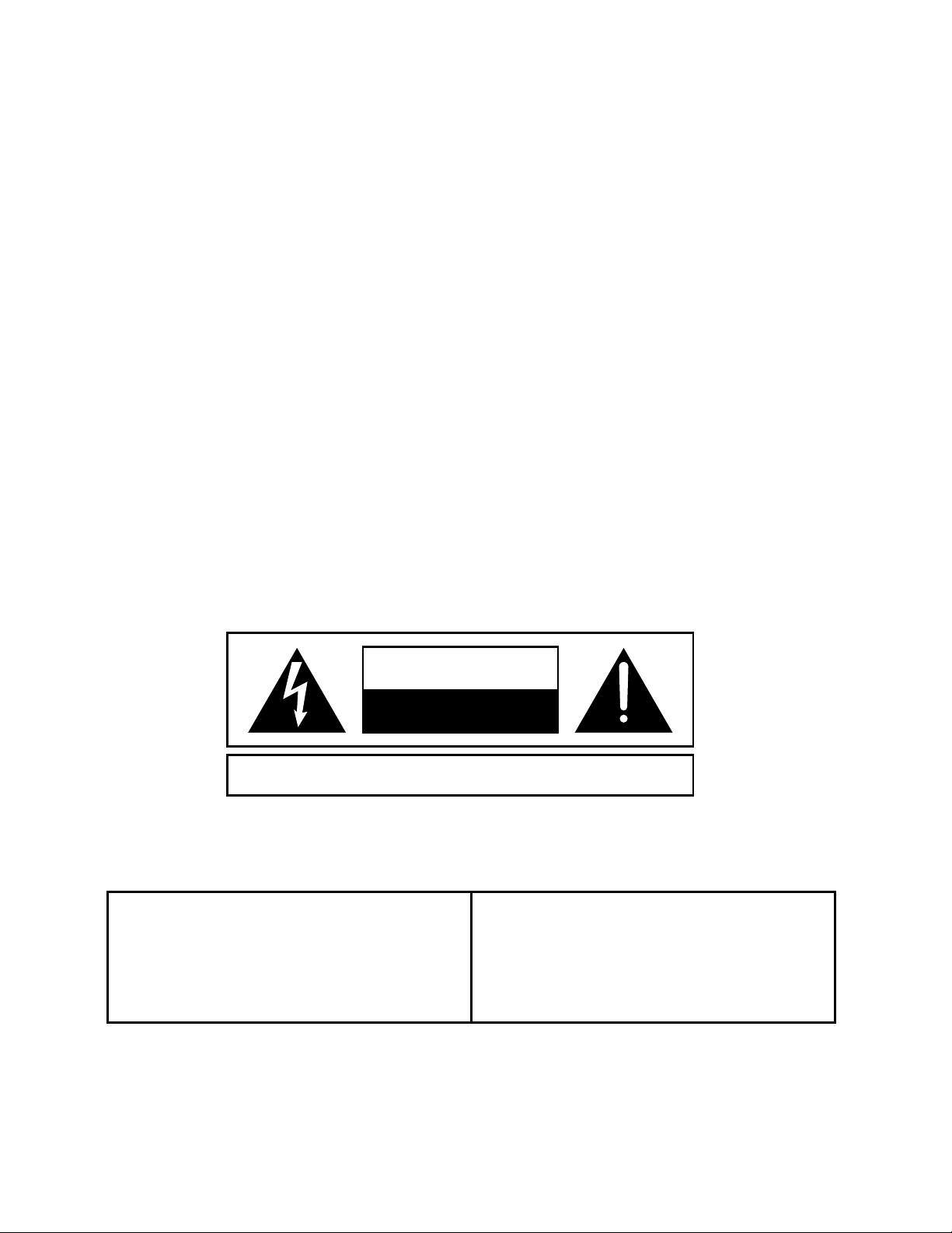
1.2.1 Equipment Markings
CAUTION
RISK OF ELECTRIC SHOCK
DO NOT OPEN
ATTENTION:
No user serviceable parts inside. Refer servicing to qualified service personnel.
Il ne se trouve a l’interieur aucune piece pourvant entre reparée l’usager.
S’adresser a un reparateur compétent.
The lightning flash with arowhead symbol
within an equilateral triangle is intended to
alert the user of the presence of uninsulated
"dangerous voltage" within the product's
enclosure that may be of sufficient
magnitude to constitute a risk of electric
shock to
ersons.
RISQUE DE CHOC ELECTRIQUE
NE PAS OUVRIR
The exclamation point within an equilateral
triangle is intended to alert the user of the
presence of important operating and
maintenance (servicing) instructions in the
literature accompanying the appliance (i.e.
this manual).
Caution
To prevent electric shock, do not use the polarized plug supplied with this appliance
with any extension cord, receptacle, or other outlet unless the blades can be fully
inserted to prevent blade exposure.
1-2
Rev 2.0, 10/29/93
Page 6

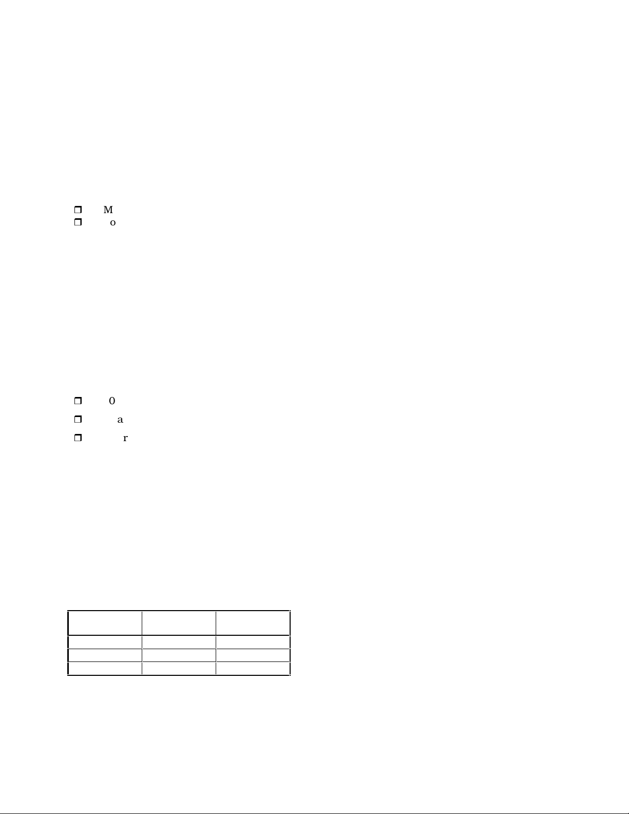
1.2.2. Terms
Several notational conventions are used in this manual. Some paragraphs may use Note,
Caution, or Warning as a heading. These headings have the following meaning:
Convention Description
Caution
NOTE
Warning
In addition, certain typefaces and capitalization are used to identify certain words. These
situations are:
Identifies information that, if not heeded, may cause
damage to the 425 or other equipment in your system.
Identifies information that needs extra emphasis. A
Note generally supplies extra information to help you
use the 425 better.
Identifies information that, if ignored, may be
hazardous to your health or that of others.
Convention Meaning
CAPITALS
Boldface
Controls, switches or other markings on the chassis.
Strong emphasis.
1.3. Other Safety Information
Power Source
This product is intended to operate from a power source
that does not apply more than 250V rms between the
power supply conductors or between either power
supply conductor and ground. A protective ground
connection, by way of the grounding conductor in the
power cord, is essential for safe operation
Grounding
Danger from Loss of
Ground
Proper Power Cord Use only the power cord and connector specified for the
Rev 2.0, 10/29/93
The chassis of this product is grounded through the
grounding conductor of the power cord. To avoid
electric shock, plug the power cord into a properly
wired receptacle before making any connections to the
product. A protective ground connection, by way of the
grounding conductor in the power cord, is essential for
safe operation.
If the protective ground connection is lost, all accessible
conductive parts, including knobs and controls that
may appear to be insulated, can render an electric
shock.
product and your operating locale.
Use only a cord that is in good condition.
1-3
Page 7

Proper Fuse
The fuse is mounted internally and is not considered
user serviceable. The fuseholder accepts American sized
fuses (1/4 in dia.) or European sized fuses (5mm dia).
For 117 VAC operation, the correct value is 1/4A,
250VAC, fast blowing (bussman type AGC)
For 230 VAC operation, the correct value is 1/8A,
250VAC, slow blowing (Bussman type MDL or GDC.
Operating Location
Stay Out of the Box
User-serviceable parts
Do not operate this equipment under any of the
following conditions: explosive atmospheres, in wet
locations, in inclement weather, improper or unknown
AC mains voltage, or if improperly fused.
To avoid personal injury (or worse), do not remove the
product covers or panels. Do not operate the product
without the covers and panels properly installed.
There are no user serviceable parts inside the 425. In
case of failure, refer all servicing to the factory.
1-4
Rev 2.0, 10/29/93
Page 8

2. Dynamics Processing Tutorial and Functional Basics
The 425 brings together three widely-used signal processors: a downward expander, a
compressor, and a peak-limiter. It's important to note that although the 425 is three
processors in one box, it contains one-third less circuitry than there would be if each
processor was in its own box. The reason is simple: there is only one VCA (voltage-controlled
amplifier) in each channel of the 425. Smart analog computer signal processing circuitry (the
sidechain by any other name) combines the three control signals from the downward
expander, compressor, and limiter to control the one VCA. There is no compromise involved in
doing this and the signal passes through two fewer VCAs.
This part of the 425 tells how to use your 425. If you are new to signal processors, read on; the
remainder of this section is a primer on the three basic parts of the 425.
2.1 Dynamics Processing Basics
Audio signals possess several basic properties: amplitude or volume (measured in volts or dB),
frequency or pitch (measured in Hertz), duration (measured in hours:minutes:seconds) and
waveform (described graphically, like sine, square, triangle, pulse). Complex signals like
musical sounds are made up of simpler waveforms such as sine waves, mixed in the proper
proportions.
Signal processors allow you to manipulate various parameters of an audio signal. Equalizers
change the amount of amplification given to different frequencies (a perfect amplifier amplifies
all frequencies by the same amount). Dynamics processors change the dynamic range of audio
signals.
The dynamic range of an audio signal is the difference between its loudest and softest
moments. For audio equipment, this is the difference between the noise floor (residual noise
output, with no input signal) and peak clipping (the point at which the output clips or
distorts). A hypothetical black-box having a noise floor of -90 dBu and a maximum peak
output level of +24 dBu would have a dynamic range of 114 dB (+24 minus -90). Audio storage
devices like tape machines have worse limitations, a typical professional analog two-track tape
machine may have a dynamic range of 65 to 70 dB.
If you've used an analog tape recorder before, then you are already familiar with the problem of
setting recording level. Record too hot and you get distortion; record too cold and get noise in
return. Many musical instruments have dynamic ranges that exceed that of most tape
recorders. So, how do we squeeze a 80 or 90 dB signal into a 60 or 70 dB window?
The answer lies in a common audio signal processor: the compressor.
2.1.1 Compressors and Limiters
A compressor or limiter monitors the level or amplitude of a signal and reduces the amplitude
according to a rule whenever the signal level exceeds a predetermined level. The
predetermined level is known as the threshold level and is usually set by a front panel control.
The rule by which the compressor lowers the level is the compressor's compression ratio and
this parameter is also usually set via a front panel control.
Compression ratio refers to the ratio of a change at the input versus the change at the output
of the device. Thus, if we apply a signal that changes 10 dB to the input of a hypothetical
compressor, and measure a 2 dB change in the output signal, that compressor would have a
compression ratio of 10:2, or 5:1 (reduce the fraction). Different compression ratios have
different uses. Use lower ratios (6:1 or less) for level control, intermediate ratios (8:1 to 12:1)
for leveling (making the signal level more or less constant), and higher ratios for limiting
(putting an absolute ceiling on the signal level).
Limiters are nothing more than compressors, but being possessed of much higher
compression ratios (20:1 or higher). Limiters are typically used to stop occasional peaks which
Rev 2.0, 10/29/93
2-1
Page 9

would have otherwise caused overload or distortion. Typically you set a limiter (via its
threshold control) so that it "stays out of the way" until a peak comes along.
2.1.2 Expanders and Gates
While a compressor or limiter reduces the dynamic range of a signal by reducing its level once
it has exceeded a threshold level, an expander does the opposite (well, almost). The easiest
way to visualize an expander is to think of it making loud signals louder. This is fine, except
that in the real world, you run into the limitations of processors and amplifiers after the
expander going into terminal overload.
The solution is to make soft signals softer, or downward expansion. This is what the 425's
downward expander does. When the signal level falls below the level set by the threshold
control, the expander reduces the gain by the amount dictated by its expansion ratio. Thus,
for a below-threshold signal, a 10 dB output change results from a 5 dB change in the input
signal, if the expansion ratio is 1:2.
A gate is similar to an expander except that its ratio is much higher; thus the action is more
like a switch once the signal falls below threshold. Some expander applications for the 425
may be quite similar to a gate, like tending a lone announce microphone, but the 425's
expander isn't well suited to typical gate applications like removing leakage from drum
microphones.
2.1.3 Ratio
The compression ratio of the 425 tells how much the output changes for a change in the
input. A linear amplifier (like a simple preamp) has a ratio of 1:1 because a change of 1 dB at
its input results in a 1 dB change at its output. A compressor alters the input/output
relationship by its compression ratio. Thus a 20:1 ratio means that a 20 dB change at the
input results in a 1 dB change at the output. In other words, a very audible change at the
input (20 dB) turns into a barely discernible change at the output (1 dB).
Compressors are not the only devices to have an input/output ratio. Any device that is
capable of changing the input/output relationship can be said to have a ratio. Thus
expanders, gates, compressors and limiters all fit this category.
An expander maginifies output changes for a given input change. Thus, once the input signal
falls below threshold, the expander changes the output by the amount of the ratio. The 425's
downward expander has an expansion ratio of 1:2, which means that an input signal that gets
5 dB quieter turns into a 10 dB quieter output change.
A gate can be looked at as an expander with an infinite expansion ratio. Thus the slightest
change in the input signal, above threshold, turns the gate full-on.
2.1.4 Gain vs Output
The gain control allows compensating for signal level lost to compression. As an example, try
setting the 425 for a 4:1 ratio. Now adjust the
as read on the compressor's gain reduction display. The output level should be significantly
lower than what it was. You supply the additional gain (make-up gain) by adjusting the
control until the input and output signal levels match.
THRESHOLD control for 10 dB of gain reduction
GAIN
2.1.5 Attack Time
The attack time represents the amount of time that a compressor (or limiter, or expander, or
gate) needs to react to an input change. You might ask, why not just make it lightning fast?
Because you may sometimes want to let occasional peaks through, which helps maintain the
dynamic characteristics of the input signal. Usually, what we're after is control of the input
signal, not total homogenization.
2-2
Rev 2.0, 10/29/93
Page 10

2.1.6 Release Time
Most dynamics processing equipment has a knob marked release on the panel. This refers to
release time, and affects the length of time required for the gain to recover to the no-signal
state.
For compressors, the no-signal point is unity gain and this applies to any signal whose level is
below threshold. For expanders the no-signal point is the gain reduction set by the threshold
control under no-signal conditions and this applies to any signal whose level is above
threshold. In this case, the release time control governs how long it takes for the expander to
reduce the gain when the signal disappears.
The release time control allows tailoring the compressor's recovery time to the program
material. Generally, peak limiting is associated with short release times and compression or
leveling associated with longer release times.
The 425's compressor release circuitry has a unique dual-release time feature designed to
make life easier. The dual-release feature makes the release time partially program dependent,
giving you the best of both worlds: fast release for short-duration peaks and a longer release
time for longer-duration peaks. The release time control adjusts the speed of the longer of the
two.
2.1.7 Threshold Setting
The threshold control sets the audio signal level where the compressor/expander/limiter
begins working. In the case of the compressor or limiter, the processor begins working once
the signal has exceeded the threshold level. For the expander, it begins working once the
signal has fallen below the threshold level.
For any of the three processors, the threshold control setting also determines the degree or
amount of gain reduction. Thus, for the compressor, rotating the control counter-clockwise
(towards -40) results in increasing amounts of compression. For the expander, counterclockwise rotation raises the level that the signal must exceed to pass through the expander
untouched. This has the effect of "shutting off" the signal once you reach and then pass the
threshold level.
For most compressor applications, moderate amounts of gain reduction are all that is
required, 3-9 dB at the most. If you are using the compressor to minimize level changes of a
wide range of program material (automatic level control), then higher amounts of gain
reduction are needed; the amount of gain reduction corresponds to the range of change that
you can respond to (slower release times are also indicated, too).
2.1.8 Interpreting the Displays
The 425 has many displays; one per processing section. The three displays associated with the
expander, compressor and limiter indicate a parameter called gain reduction. Simply stated,
the gain reduction indication shows how far the gain or amplification was reduced from unity.
Another way of looking at this is: if the gain reduction display says 10 dB of gain reduction,
switching the unit to bypass will result in a 10 dB increase in the output level.
The output display indicates output level, in VU (0 VU = +4 dBm = 1.23V RMS measured at
the balanced outputs). For most applications, just make certain that you never see the CLIP
LED illuminate.
2.2 Using the Sidechain
The sidechain is a patch point in the control circuit of a dynamic range processor, which
provides access to the part of the circuitry that tells the VCA what to do. The 425's sidechain
is routed through a TRS jack located on the rear panel that provides both a send and return
via the same jack. The sidechain connection affects all three processors in the 425.
Rev 2.0, 10/29/93
2-3
Page 11

Look at the block diagram in Section 7. Notice the sidechain connections that come from the
balanced input stage. They allow access to the control circuit's input signal. The control signal
is derived from, but kept totally separate from, the audio signal path. This means the control
signal can be processed outside the 425 without actually processing the signal that's going
through the VCA (the audio signal itself). This presents some very interesting possibilities for
changing or improving the operation of the dynamic range processor.
The best use of the sidechain is to make the action of the 425's compressor/limiter/expander
frequency dependent, that is, to make it respond more (or less) to certain frequencies. Because
the audio signal and the control signal remain completely separate (even while the control
circuit tells the VCA whether to turn the gain up or down), you can equalize the sidechain
without changing the EQ in the main audio path.
Removing unwanted frequencies from the control signal before it actually reaches the VCA
prevents those frequencies from being used to create gain changes. Perhaps most importantly,
this happens without actually equalizing the signal being processed through the 425.
To make the 425's processors more sensitive to high frequencies, use an equalizer (graphic or
parametric) to boost the high frequencies in the sidechain signal. This increases the sensitivity
of the control circuits to those particular frequencies so the compressor/limiter/expander
responds more to those frequencies than any others. If the offending frequencies produce a
control signal of greater amplitude than the desired frequencies they will control how the
compressor/limiter/expander behaves with the rest of the signal as well. However, if the
offending signals are of significantly greater amplitude than the rest of the signal, careful
adjustment of the corresponding threshold control (combined with the boost provided by the
EQ in the sidechain) will make the compressor/limiter/expander respond only to the boosted
frequencies.
Keep in mind that the threshold level becomes a function of the amount of overall gain
through the equalizer, including the boost. This technique can be used with any frequency
that can be controlled by the equalizer.
Cutting a frequency creates the inverse effect, making the 425 less sensitive to the frequencies
that were removed from the control signal.
Since the expander only discriminates between different levels (not different sounds), it can be
fooled by signals whose levels are nearly the same, even if the frequency content of those
signals is fundamentally different. When the 425's expander is used to shut out unwanted
sounds, any signal exceeding the threshold setting triggers the expander. When this happens,
it's often possible to eliminate the false triggering by equalizing the control signal.
For example, if low frequency signals transmitted through a desk or podium are triggering the
425's expander unnecessarily:
❒ Use an equalizer in the sidechain to remove the low frequencies from the control
signal.
and/or
❒ Use the equalizer to boost the voice-range frequencies in the control signal.
When the offending frequencies are removed or minimized, the relative level of the desired
frequencies increases and the expander can now tell the difference between the wanted and
unwanted signals. Use this technique in any situation where levels are nearly the same, but
the fundamental frequencies involved are different.
2-4
Rev 2.0, 10/29/93
Page 12

NOTE The ability of the expander to discriminate between wanted and unwanted
signals is partially determined by mic technique. Be particularly careful of high
frequency sounds entering the side or rear pattern of a cardioid mic. Most
cardioid mics exhibit a sharply rising off-axis response characteristic at higher
frequencies. Check the off-axis curve (the lower one) in the manufacturer's
literature. If there's only a 3dB to 6dB difference between the on-axis (frontal)
response and the off-axis (side or rear) response in the 5kHz to 10kHz reason,
high frequency sounds will be picked up by the side or back of your mic.
Use the mic's directional pattern to keep other sources as far off-axis as
possible - do everything you can do to extract all the source-to-source
discrimination possible through good mic technique. The sounds picked up by
individual mics must be primarily the sound of the desired signal, or the
expander won't be able to tell the difference.
Hint: You can save time, and make life easier by listening to the output of the
equalizer (instead of the 425's output) that you're using in the sidechain. Doing
this allows you to hear the signal that will control the 425, and perhaps to find
the range that you wish to emphasize or de-emphasize more easily.
Rev 2.0, 10/29/93
2-5
Page 13

Notes
2-6
Rev 2.0, 10/29/93
Page 14

3. Technical Tutorial
This section discusses a multitude of things, all related to getting signals in and out of the
425.
3.1. Matching Levels vs Matching Impedances
In any audio equipment application, the question of "matching" inevitably comes up. Without
digging a hole any deeper than absolutely necessary, we offer the following discussion to
(hopefully) clarify your understanding of the subject.
Over the years, we have all had impedance matching pounded into our heads. This is
important only for ancient audio systems, power amplifiers, and RF. Technically speaking, the
reason is power transfer, which reaches a maximum when source and load are matched.
Modern audio systems are voltage transmission systems and source and load matching is not
only unnecessary, but undesirable as well.
❒ Ancient audio systems operate at 600 ohms (or some other impedance value), and must
be matched, both at their inputs and at their outputs. Generally speaking, if you are
dealing with equipment that uses vacuum tubes, or was designed prior to 1970, you
should be concerned about matching. These units were designed when audio systems
were based on maximum power transfer, hence the need for input/output matching.
❒ Power amplifiers are fussy because an abnormally low load impedance generally means a
visit to the amp hospital. Thus, it's important to know what the total impedance of the pile
of speakers connected to the amplifier really is.
❒ RF systems are matched because we really are concerned with maximum power transfer
and with matching the impedance of the transmission line (keeps nasty things from
happening). Video signals (composite, baseband, or otherwise) should be treated like RF.
Some folks seem to believe that balanced/unbalanced lines and impedances are related; or
even worse that they are associated with a particular type of connector. Not so. Unbalanced
signals are not necessarily high-impedance and balanced signals/lines are not necessarily
low-impedance. Similarly, although 1/4 inch jacks are typically used for things like guitars
(which are high-impedance and unbalanced), this does not predispose them to only this
usage. After all, 1/4 inch jacks are sometimes used for loudspeakers, which are anything but
high-impedance. Therefore, the presence of 3-pin XLR connectors should not be construed to
mean that the input or output is low-impedance (or high-impedance). The same applies to 1/4
inch jacks.
So, what is really important? Signal level, and (to a much lesser degree), the impedance
relation between an output (signal source) and the input that it connects to (signal receiver).
Signal level is very important. Mismatch causes either loss of headroom or loss of signal-tonoise ratio. Thus, microphone inputs should only see signals originating from a microphone, a
direct (DI) box, or an output designated microphone-level output. Electrically, this is in the
range of approximately -70 to -20 dBm. Line inputs should only see signals in the -10 to +24
dBm/dBu range. Guitars, high-impedance microphones, and many electronic keyboards do
not qualify as line-level sources.
The impedance relation between outputs and inputs needs to be considered, but only in the
following way:
Always make sure that a device's input impedance is higher than the output
source impedance of the device that drives it.
Some manufacturers state a relatively high-impedance figure as the output impedance of their
equipment. What they really mean is that this is the minimum load impedance that they
would like their gear to see. In most cases, seeing a output impedance figure of 10,000 (10K)
ohms or higher from modern equipment that requires power (batteries or AC) is an instance of
Rev 2.0, 10/29/93
3-1
Page 15
this type of rating. If so, then the input impedance of the succeeding input must be equal to or
greater than the output impedance of the driving device.
Symetrix equipment inputs are designed to bridge (be greater than 10 times the actual source
impedance) the output of whatever device drives the input. Symetrix equipment outputs are
designed to drive 600 ohm or higher loads (600 ohm loads are an archaic practice that won't
go away). You don't need to terminate the output with a 600 ohm resistor if you aren't driving
a 600 ohm load. If you don't understand the concept of termination, you probably don't need
to anyway.
The two facts that you need to derive from this discussion are:
r
Match signal levels for best headroom and signal-to-noise ratio.
r
For audio, impedance matching is only needed for antique equipment and power
amplifier outputs. In all other cases, ensure that your inputs bridge (are in the range of
2 to 200 times the output source impedance) your outputs.
3.2. Signal Levels
The 425 is designed around studio/professional line levels: +4 dBu or 1.23 volts RMS. The
unit is quiet enough to operate at lower signal levels such as those found in semi-pro or
musical-instrument (MI) equipment (-10 dBu or 300 millivolts).
3.3. I/O Impedances
The 425 is designed to interface into almost any recording studio or sound reinforcement
application. This includes:
r
600 ohm systems where input and output impedances are matched.
r
Unbalanced semi-professional equipment applications.
r
Modern bridging systems where inputs bridge and outputs are low source impedances
(voltage transmission systems).
The 425's input impedance is greater than 30-kilohms balanced or unbalanced. The inputs
may be driven from any source (balanced or unbalanced) capable of delivering at least -10 dBu
into the aforementioned impedances.
The 425's output impedance is 300 ohms balanced, 150 ohms unbalanced. The output line
driver delivers +23 dBm into 600 ohm balanced loads or +18 dBm into 600 ohm unbalanced
loads.
3.4. Polarity Convention
The 425 uses the international standard polarity convention of pin 2 hot. Therefore:
If your system uses balanced inputs and outputs,
XLR Tip-Ring-
Signal
Sleeve
1 Sleeve Ground
2 Tip High
3 Ring Low
and uses the 425 this way, then the polarity
convention is unimportant. If your system is both
balanced and unbalanced, then you must pay
attention to this, especially when going in and
coming out through different connector types
(like input on an XLR, output on a phone jack).
3-2
Rev 2.0, 10/29/93
Page 16

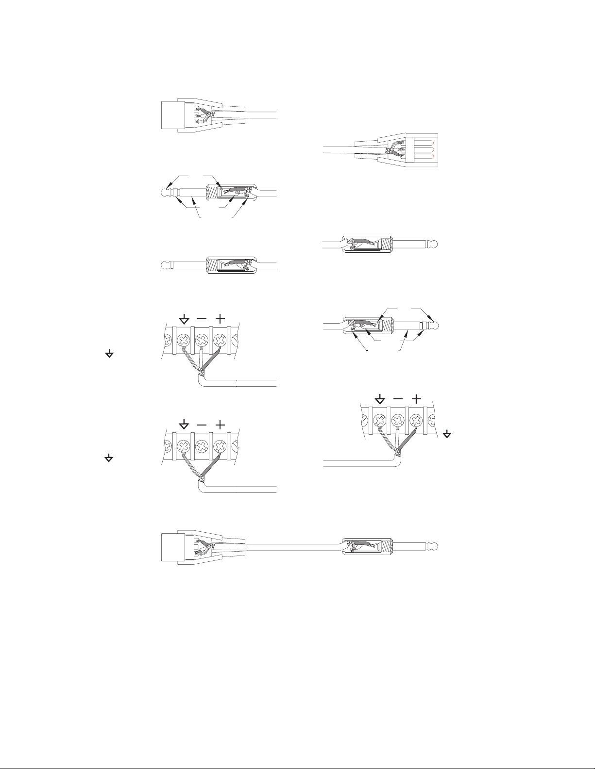
3.5. Input and Output Connections
Figure 3-1 illustrates how to connect the 425 to balanced and unbalanced sources and loads.
To operate the 425 from unbalanced sources, run a 2-conductor shielded cable (that's two
conductors plus the shield) from the source to the 425. At the source, connect the low/minus
side to the shield, these connect to the source's ground; connect the high/plus side to the
source's signal connection. At the 425, the high/plus wire connects to pin 2, the low/minus
wire connects to pin 3, and the shield (always) connects to pin 1. This is the preferred method
as it makes best use of the 425's balanced input (even though the source is unbalanced). The
other alternative shown in Figure 3-1 converts the 425's balanced input into an unbalanced
input at the input connector. This works, but is more susceptible to hum and buzz than the
preferred method. There is no level difference between either method.
You can drive unbalanced loads with the 425's outputs by using the XLR connector with pin 3
left open. In an emergency (the show must go on), you can ground pin 3, but if you have the
choice...leave it open. If you must ground pin 3, it is must be grounded at the 425, rather than
at the other end of the cable. The price, regardless of whether or not pin 3 is grounded is 6 dB
less output level. This can be easily made up via the output gain controls. If your system is
wired with pin 3 hot, pin 2 must float if you are driving an unbalanced load.
The 1/4-inch input jack is paralleled with the XLR-input and the screw terminals. In a large
installation, it is permissible to use one of the connectors as the input connection and to use
either or both of the remaining connections for paralleling other inputs with the 425.
The 1/4 inch output jack is a TRS (tip-ring-sleeve) jack wired for unbalanced operations. That
is, the tip is the signal connection, and the ring and sleeve connections both go to circuit
ground. This style of connection assures operation (passage of signal) regardless of the type of
plug inserted into the jack. The unbalanced output is always 6 dB lower in level than the
balanced output.
Rev 2.0, 10/29/93
3-3
Page 17
FROM BALANCED OUT
FEMALE XLR
PIN 1 = GROUND
PIN 2 = HIGH
PIN 3 = LOW
FROM BALANCED OUT
MALE TRS PLUG
TIP = HIGH
RING = LOW
SLEEVE = GROUND
FROM UNBALANCED OUT
MALE TS PLUG
SLEEVE = GROUND +
TIP = HIGH
LOW
2
3
1
TO BALANCED IN
1
3
2
TIP
RING
SLEEVE
TO UNBALANCED IN FROM
TRANSFORMER COUPLED OR
FLOATING BALANCED OUTPUT
MALE XLR
PIN 1 = GROUND
PIN 2 = HIGH
PIN 3 = LOW
MALE TS PLUG
TIP = HIGH
SLEEVE = GROUND +
LOW
FROM BALANCED OUT
TERMINAL STRIP
(+) = HIGH
(-) = LOW
= GROUND
FROM UNBALANCED OUT
TERMINAL STRIP
(+) = HIGH
(-) = NOT USED
= GROUND
FROM NON-TRANSFORMER (ELECTRONIC)
PIN 1 = GROUND + LOW
PIN 3 = NOT USED
BALANCED OUTPUT
(TYPICAL OF SYMETRIX PRODUCTS)
FEMALE XLR
PIN 2 = HIGH
TO BALANCED IN
TIP
RING
SLEEVE
MALE TRS PLUG
TIP = HIGH
RING = LOW
SLEEVE = GROUND
TO BALANCED IN
TERMINAL STRIP
(+) = HIGH
(-) = LOW
= GROUND
TO UNBALANCED IN
2
3
1
MALE TS PLUG
TIP = HIGH
SLEEVE = GROUND +
REV-B
LOW
3-4
Figure 3-1. Input and output connector wiring. These diagrams represent
the majority of connectors used in modern audio equipment. Locate the
source connector in the left column and match it up with the destination
connector in the right column. Wire your cable according to the diagrams.
Rev 2.0, 10/29/93
Page 18

4. Front Panel Overview
EXPANDER
THRESHOLD (dBu)
-20
-5 -30
+5
BYPASS
RELEASE
FAST
SLOW
THRESHOLD (dBu)
-10
+10 -25
-40
BYPASS
-8 -6 -10 -12 -25 -15 -2 -6 -12 -18
FAST
-4
RELEASE
COMPRESSOR
1.3 2.5
SLOW
RATIO (X:1)
10
THRESHOLD (dBu)
+5 2
-2.5
-10 1
0VU CLIP-20 -3
-10 -6 -9 -12 -2
LIMIT
GAIN (dB)
+10
+12.5 +5 +15
0
+20 BYPASS
OUT
IN
BYPASS
DUAL STEREO
LINK
STEREO
DUAL MONO
The 425 has the following controls, switches, and indicators on its front panel:
Expander
T
HRESHOLD
RELEASE
LED Display The expander display indicates how much the expander has
Sets the signal level below which the expander begins to
operate. When the input signal falls below the level indicated
on the knob, the expander begins reducing the gain. The LED
display above the knob indicates how much the expander has
reduced the gain.
Determines the speed at which the expander reduces the gain
for an instantaneous change in the input signal (below
threshold). Use the
RELEASE control to prevent the expander
from punching holes in the input signal.
reduced the level of the input signal.
Compressor
T
HRESHOLD
Sets the level above which the compressor begins reducing the
output level.
RELEASE
Determines the speed at which the compressor restores the
gain for an instantaneous change in the input signal. Use the
RELEASE control to smooth the action of the compressor on
staccato material.
RATIO
Determines the amount of change in the output for a given
change in the input. If the ratio control is set to 10:1, this
means that the output will change 1 dB (not much) for a 10 dB
(3.16 times) change in the input. Use higher ratios to control
peaks and lower ratios to smooth out average levels.
LED Display Indicates how much the output level has been reduced by the
compressor.
Limiter
T
HRESHOLD
LED Display Indicates how much the output level has been reduced by the
Sets the level above which the limiter begins reducing the
output level.
limiter. -3 to -6 dB indications are a good place to start.
Rev 2.0, 10/29/93
4-1
Page 19

Other Controls Switches and Displays
G
AIN(DB)
LED Display Indicates the output level of the 425.
Increases the output level of the 425. Use this control to
restore signal level lost by compression or limiting.
Note: the unity gain position of the control (0 dB) is referenced
to the balanced output connector. If you are using the
unbalanced output, unity gain occurs when the the
control is set to +6 dB.
GAIN
IN/BYPASS
DUAL / STEREO
This switch bypasses the 425. This is NOT a hard-wire bypass;
the 425 will not pass signal unless the unit is powered and
turned on.
This switch selects dual-mono or stereo-coupled mode. In
dual-mono mode, each channel of the 425 operates
independently.
In stereo-coupled mode, the channel 1 controls determine the
settings for both channel 1 and channel 2. Channel 1's
sidechain receives a mono mix of the channel 1 and channel 2
signals. The LED displays for channel 2 blank (except for the
output display) to remind you that the channels are stereocoupled.
The remaining controls and switches on the front panel
duplicate those previously described for channel 1.
4-2
Rev 2.0, 10/29/93
Page 20

5. Rear Panel Overview
O
D
12.5W MAXIMUM
MANUFACTURED IN
SEATTLE WASHINGTON,
UNITED STATES OF AMERICA
POWER
TIP=RETURN
RING=SEND
SLEEVE=GROUND
SIDECHAIN
IN/OUT
OUTPUT
UNBALANCED
BALANCED
SIDECHAIN
IN/OUT
UNBALANCED/
INPUT
BALANCED BALANCED
The following connectors and features are found on the rear panel of the 425.
Serial Number Do yourself a favor and write this number down somewhere
safe, and while you're at it, please send us the completed
warranty card?
power cord IEC power receptacle. Connect the power cord to an
appropriate source of AC power. Observe the marked power
supply voltage on rear panel.
UNBALANCED OUTPUT
1/4 inch tip-ring-sleeve (TRS) phone jack (wired tip = hot, ring
& sleeve = ground). Use this jack when you need an
unbalanced output. The nominal signal level here is +4 dBu.
Note: the
lower in level than the
easily make up the difference in level via the front panel
UNBALANCED OUTPUT connector is normally 6 dB
BALANCED OUTPUT connector. You can
GAIN
control.l
BALANCED OUTPUT
XLR-3 male connector. Use this connector when you need a
balanced output. The nominal signal level here is +4 dBu.
XLR PIN 2 = HI
XLR PIN 3 = L
XLR PIN 1 = GN
SIDECHAIN IN/OUT
1/4 inch tip-ring-sleeve connector. This is both an input and
output on the same connector (tip = input/return, ring =
output/send). Use this connector to connect equalizers and/or
filters into the 425's sidechain for frequency-selective
processing. The wiring diagram for the sidechain in/out
connector is reproduced on the back panel of the 425.
UNBALANCED/BALANCED
INPUT
1/4 inch TRS phone jack. This connector is wired in parallel
with the XLR input connector. Connect either balanced or
unbalanced sources here. Use a tip-sleeve plug for unbalanced
sources and a tip-ring-sleeve (stereo) plug for balanced
sources.
BALANCED INPUT
XLR-3 female connector. This connector is wired in parallel
with the TRS input connector. Connect balanced sources here.
The remaining connectors on the rear panel are the channel 1 input/output/sidechain
connectors. These connectors duplicate those used for channel 2.
Rev 2.0, 10/29/93
5-1
Page 21

Notes
5-2
Rev 2.0, 10/29/93
Page 22

6. Fast First Time Setup
Follow these instructions to get your 425 up-and-running as quickly as possible. The intent of
this section is fast setup. If you need something clarified, then you'll find the answer
elsewhere in this manual.
6.1 Connections
Connect the line-level signal source to either the female XLR connector or the 1/4 inch TRS
(tip-ring-sleeve, stereo, 3 conductor) input jack. If the source is unbalanced, then use a 1/4
inch TS (tip-sleeve, mono, or guitar) plug fully inserted into the TRS input jack.
Connect the line-level signal return to either the male XLR connector or to the 1/4 inch TRS
output jack. If you use the 1/4 inch jack, then use a TRS plug for balanced circuits or use a
TS plug for unbalanced circuits. Additional information on the signal connections may be
found in the Installation section of this manual.
Repeat for the second channel. Ignore the sidechain connections for now.
Connect the AC input to an AC power source of the proper voltage and frequency, as marked
on the rear of the unit.
Caution: Failure to connect the 425 to the proper AC mains voltage may
cause fire and/or internal damage. There are no user serviceable parts inside
the chassis. Refer all service to qualified service personnel or to the factory.
Warning: Lethal voltages are present inside the chassis. There are no
user serviceable parts inside the chassis. Refer all service to qualified
service personnel or to the factory.
AMP
= HIGH = 1/4" TIP
LOW = 1/4" RING
GND = 1/4" SLEEVE
UNBALANCED UNBALANCED/
BALANCED
SIDECHAIN
IN/OUT
LINE LEVEL
BALANCED
INPUTOUTPUT
BALANCED
LINE LEVEL
Rev 2.0, 10/29/93
6-1
Page 23

6.2 Settings
Make your initial switch and control settings as follows:
Usage Switch Setting
Dual mono
IN/BYPASS
depressed
10
out
depressed
depressed
-12 -9 -6 -3
+5
-2.5 +12.5
-10
BYPASS
LIMIT
CLIP0VU-10 -20 STEREO
GAIN (dB)
+10
+5 +15
0
+20
OUT
IN
BYPASS
DUAL
Stereo
-18 -12 -6 -2 -10 -12 -15 -25
THRESHOLD (dBu) RELEASE
-20
-5 -30 +10 -25
+5
BYPASS
FAST
THRESHOLD (dBu) THRESHOLD (dBu)
-10
-40
SLOW
BYPASS
STEREO/DUAL
IN/BYPASS
STEREO/DUAL
-8 -6 -4 -2
FAST
SLOW
COMPRESSOREXPANDER
RATIO (X:1)RELEASE
2
1.3 2.5
1
Control Setting Control Setting Control Setting
Expander: Compressor: Peak Limiter:
THRESHOLD
RELEASE
-20
12 o'clock
THRESHOLD
RELEASE
RATIO
-10
12 o'clock
10:1
THRESHOLD
GAIN
+5
0
6.3 Initial Setup
LINK
STEREO
DUAL MONO
The 425's controls and switches are now set according to the preceding section. All
connections listed in Section 6.1 are now made. The 425 should now pass signal. The LED
display should be illuminated.
Set the input level by increasing the setting of the input level control until the amber LEDs in
the
HEADROOM display illuminate. Ideally, the highest signal level should illuminate the -1 dB
LED, and the
CLIPPING LED should almost never illuminate (the CLIPPING LED operates 1 or 2
dB below clipping.).
6.4 Refining Your Settings
For most signals, the above settings should produce activity in each section of the 425. The
expander and compressor sections tend to be complementary, that is, you probably won't be
showing expansion when the signal level is high enough to cause compression.
Whenever the operation of two of the sections of the 425 overlaps (especially the compressor
and limiter sections), whichever section has the highest gain-reduction reading on its display
is the section controlling the signal at that instant.
Refine the expander
signal falls below the threshold setting. You can make the expander "ignore" momentary
lapses in signal by increasing the setting of the
release once the signal falls below-threshold.
THRESHOLD setting so that the expander reduces the gain when the input
RELEASE control. This also affects the rate-of-
6-2
Rev 2.0, 10/29/93
Page 24

Refine the compressor THRESHOLD setting so that the compressor display shows the amount of
gain reduction desired when the signal is within the operating range of the compressor. For
most applications, 3 to 6 dB are all that's necessary. Choose a
your application: gentle level control demands low ratio settings (below 6:1), peak leveling
requires higher settings (8:1 or higher). Choose a
sounds like fast release times, speech and music like slower times. These settings are just
guidelines, you can use whatever setting actually works.
If you're using a large amount of compression, for leveling or automatic gain control, you may
need to adjust the output
lost to the compressor. You can set the makeup gain easily by comparing signal levels via the
GAIN control to add makeup gain to compensate for the signal level
RELEASE time accordingly: percussive
RATIO setting appropriate for
IN/BYPASS switch and adding gain via the GAIN control
Refine the peak limiter
reduction during the highest peaks, and then only momentarily. Large amounts of gain
reduction showing on the peak limiter's display indicate that the limiter
may be too low. If this is what you want, fine, but bear in mind that peak limiters are designed
to stop occasional peaks dead, and may not sound very pretty used semi-continuously. May
we suggest using the compressor with the ratio control set at maximum.
THRESHOLD setting so that the peak limiter display only shows gain
THRESHOLD setting
6.5 Stereo Coupling
If you are using the 425 for a stereo signal, say for a stereo mixdown, depress the LINK switch
so that the
VCAs together. Channel 1 's sidechain receives an equal mix of the two input signals. Only
Channel 1's controls work (they control both channels now). The end result is the gain
reduction applied to the two channels is identical, which prevents stereo image shifts caused
by unequal gain reduction in the two stereo channels.
STEREO LED is lit. This disables the channel 2 control channel, and slaves the two
Rev 2.0, 10/29/93
6-3
Page 25

Notes
6-4
Rev 2.0, 10/29/93
Page 26

7. Using the 425
The 425's design emphasizes ease-of-use. This doesn't mean that we made it easy to use by
removing everything except the power switch; instead we concentrated on keeping the controls
that really make a particular feature work well and eliminating those that didn't. This section
contains installation information and descriptions of each of the front and rear panel controls,
switches, and connectors.
7.1 Block Diagram
Figure 7-1 is the block diagram of the 425.
SSERP
BALANCED
INPUT
UNBALANCED/
BALANCED
INPUT
PEAK
CIRCUIT
THRESHOLD
LIMITER
CIRCUIT
IN/OUT
SWITCH
VCA
BALANCED
OUTPUT
UNBALANCED
OUTPUT
SIDECHAIN
IN/OUT
TO/FROM CH2
SIDECHAIN
TO/FROM CH2
VCA CONTROL VOLTAGE
STEREO LED
DUAL LED
TO ALL CH2 LEDS
(EXCEPT OUTPUT LEDS)
LOG
AMP
LINK SWITCH
(SHOWN IN STEREO)
CIRCUIT
+V
+V
THRESHOLD
RMS
RELEASE
EXPANDER
CIRCUIT
COMPRESSOR
CIRCUIT
LIMITER LEDS
OUTPUT LEDS
GAIN
RATIORELEASETHRESHOLD
EXPANDER LEDS
COMPRESSOR LEDS
OUTPUT
LEVEL
Figure 7-1. Block Diagram (one channel shown).
Please take a moment and take note of the following:
❒ There is only one VCA per channel.
❒ Bypass mode is not a hard-wire bypass for each channel.
❒ The TRS, and XLR input connectors are all paralleled.
❒ The TRS output jack is wired for unbalanced operation (tip hot, ring and sleeve grounded).
7.2 Installation
The 425 may be installed free-standing or rack mounted. No special ventilation requirements
are necessary.
Installation Requirements
Mechanical One rack space (1.75 inches) required, 10 inches depth (including
connector allowance). Rear chassis support recommended for road
applications.
Electrical 105-125 VAC, 50-60Hz, 12.5 Watts maximum.
Connectors XLR-3 female for inputs, XLR-3 male for outputs, Pin 2 of the XLR
connectors is "Hot." TRS female connectors are also provided.
Note: the unbalanced output uses a TRS output jack with the ring
and sleeve connections connected to circuit ground.
Rev 2.0, 10/29/93
7-1
Page 27

7.3 The 425 as a Compressor
O
O
You can use the 425 as a compressor in two different ways:
1. the compressor operates occasionally, dispatching occasional peaks.
2. the compressor operates continuously, making the dynamic range smaller at the output.
For the first scenario, pick a threshold setting that results in occasional gain reduction, as
displayed on the compressor display. Use a ratio setting suitable for your application; low
(1.3:1 to 2.5:1 for gentle compression, higher for more drastic squashing). Low ratios are
harder to hear, consequently you can operate with 6 dB or so of compression, without too
many audible effects. Higher ratios require subtlety, especially in threshold selection. Pick
your threshold setting so that no more than 6 dB of gain reduction occurs and you'll get the
signal control that you need, without being too obvious. Pick a release setting that lets the
gain recover fairly quickly.
Scenario two requires low ratio settings (unless you don't care about being obvious), and a
lower (-10 or lower) threshold setting. Choose a threshold setting that results in more or less
continuous gain reduction. Pick the ratio setting so that the dynamic range of the output
signal corresponds to the maximum and minimum signal levels that you want. Pick a release
setting that allows gain recovery during longer pauses.
7.4 The 425 as a Ducker
Well, almost. First, what is a ducker? (Hint: It's not something twisted utilizing waterfowl.) It is
a way of making the level of one audio signal follow that of another. A prime example would be
an announcer (the ducker) talking over a music bed (the duckee). What most people do is to
simply ride the music facer when the announcer is talking. You can do the same thing
automatically by using a compressor having a sidechain connection.
Now for some people, a "true" ducker must reduce the level of the duckee to some preset level
whenever the ducker signal is present. The 425 will not do this. It will,however, reduce the
level of the duckee whenever the ducker is present, but the amount of gain reduction follows
the envelope of the
ducker signal. Get it?
See Figure 7-1 for a
DUCKEE
LUME
V
TIME
LUME
V
TIME
DUCKER
OUTPUT
Figure 7-1. Signal relationships in a ducker.
more graphic
description.
Anyway, if this
"limitation" isn't a
problem, then refer to
Section 8.4 for
hookup. The ratio
control determines the
talkover ratio (how
much the duckee gets
reduced for a change
in the ducker) and the
threshold control
determines the total
amount of ducking
action. The release
time control govern's
how rapidly the
7-2
Rev 2.0, 10/29/93
Page 28

duckee recovers after being ducked. Don't be meek with the knobs, most ducker applications
require 20+ dB of gain reduction to be effective.
7.5 The 425 as a Limiter
The peak limiter section of the 425 is a fast-acting (200µS), steep slope (20:1) limiter. Peak
limiters are generally used to stop signal peaks dead in their tracks. The peak limiter in the
425 has only one control: threshold. Set the control for occasional -3 dB gain reduction
indications (you can let it hit 6 dB once in a great while). If you allow more gain reduction
than 3-6 dB, that's ok, but
the results may be quite
O
10
u
+2.5
t
0
p
u
-10
t
-20
Downward
Exp.
-10
Linear
1:1
Compression
4:1
Limiting
10:1
Input
Figure 7-2. Simultaneous downward-expansion, compresion and limiting.
0dB or higher, and limiter threshold high enough to catch the highest peaks (or at recording
media overload). The compressor catches most peaks, using a moderate ratio (which is more
ear-pleasing), while the limiter gives you the freedom from overload that only a peak limiter
can give.
audible (peak limiters are
designed to stop peaks, not
to sound pretty).
You can use the 425 as a
dual-threshold peak
limiter, with a gentle slope
for lower-level peaks and a
steep slope (20:1) for high-
40302520151050-5-20 -15
level peaks by setting the
compressor ratio at 4:1,
compressor threshold at
7.6 The 425 as an Expander
As described before, the expander section of the 425 is a downward expander. When the input
signal falls below the threshold control setting, the 425 reacts by reducing the gain of the
VCA. This increases the dynamic range of the output signal (since the soft just got softer).
You can use the expander to reduce body noises picked up by an announce microphone, or to
reduce amp noise from a noisy guitar amp, or how about reducing the amount of room sound
in a guitar track that was recorded a little too loosely in a room that was a little too noisy? For
sound reinforcement, how about using the expander to tend an announce mic that needs to
be left on, but you really don't want it picking up every whisper in its vicinity.
Setup is easy, with no signal, adjust the
THRESHOLD control counter-clockwise until you begin
to see gain reduction on the expander's LED display, continuing until you hear the degree of
expansion that you want. When the signal is present, you may need to refine the setting so
that the expander doesn't reduce the gain during momentary pauses. You can slow things
down a bit via the
RELEASE control, which helps prevent expansion during momentary pauses.
7.7 Using the Expander and Compressor Simultaneously
There are times when you might want to expand and compress simultaneously. Now this isn't
a game of tug-of-war between the expander and compressor. How about a track that has too
much dynamic range and needs to be squashed to fit into the space available in your mix?
After squashing, you notice a lot of room noise, amp noise, etc. whenever the track is not
active. 425 to the rescue. Simply adjust the expander threshold to cause gain reduction
during the quiet parts of the track and you'll make those ugly noises disappear.
Rev 2.0, 10/29/93
7-3
Page 29

Another application for simultaneous expanding and compressing is voice processing. Close
mic'ed voices tend to be a little un-natural. Things that we don't hear at conversational
distance are heard quite well by the announce microphone. A bit of expansion will help to
reduce lip-smacking noises and some compression will help even levels out and generally
tighten up the sound.
7-4
Rev 2.0, 10/29/93
Page 30

8. Applications
Here are a few applications that the 425 lends itself to. The following applications make one
assumption: settings for the threshold control(s) are a function of each individual system's
actual operating level. Wherever specific threshold settings are mentioned, they are referenced
to either a particular gain reduction level as indicated by the meter, or to a O dBu input level.
8.1 Vocal Level Smoothing
This application assumes that the voice source does not vary tremendously in level. Examples
of this include narration, commercial voice-over production, seminar speaking, etc.
-25 -15 -12 -10
THRESHOLD (dBu)
-10
-25 +10
-40
BYPASS
-4 -6 -8
-2
COMPRESSOR
RELEASE RATIO (X:1)
FAST
SLOW
1
q
Lower the threshold setting until the gain reduction display
begins to show compression, then continue lowering the
2
2.51.3
10
setting until the display shows 6-9 dB of gain reduction on
peaks.
q
To eliminate noises like paper rattling or breathing, try
using the downward expander.
8.2 Removing Noise from Vocal Tracks
Sometimes, due to the more abrupt nature of gating, it may be more appropriate to clean up a
noisy vocal track with a downward expander. The 425's expander is smooth, and can clean up
vocals without cutting into phrasing.
-2 -6 -12 -18
EXPANDER
FAST
RELEASETHRESHOLD (dBu)
SLOW
-20
-30 -5
+5
BYPASS
q
Set the expander threshold for 16 dB (or more) of gain reduction
when the signal source is silent, and 0 dB of gain reduction when the
signal is present.
q
Use the release control to make the expander follow the phrasing.
8.3 Constant Level Paging
All too often, paging announcements are either sub-audible, or distorted. The problem is the
result of changing input levels from different users (timid Tom vs Sam Screamer) and
unpredictable environmental circumstances. To optimize system levels for intelligibility
without overload, use the compressor section to even out levels, and the peak limiter to put a
clamp on Sam Screamer.
q
-25 -15 -12 -10
THRESHOLD (dBu)
-10
-25 +10
-40
BYPASS
Rev 2.0, 10/29/93
-4 -6 -8
RELEASE RATIO (X:1)
FAST
-2
COMPRESSOR
SLOW
2
2.51.3
1
10
Set the compressor threshold for 6 dB of gain reduction
with normal paging levels.
q
Set the peak limiter threshold for 6 dB of gain reduction
when Sam Screamer is on the system.
q
All normal signals will be slightly compressed, and really
loud signals will activate the peak limiter. With these
settings a shy person will be audible, and the guy who
thinks he has to shout won't be too loud, or cause
distortion.
8-1
Page 31

8.4 Paging with Ducking
Many situations involving a "talking host" and any sort of musical background will require the
background music to drop in level whenever the host signal is present. By splitting the host
signal, part of it can be used to tell the 425 when to take action and lower the background
source by an amount determined by the threshold control.
-18 -12 -6 -2
THRESHOLD (dBu) RELEASE
-20
-5 -30 +10 -25
+5
BYPASS
FAST
THRESHOLD (dBu) THRESHOLD (dBu)
-10
-40
SLOW
BYPASS
-8 -6 -4 -2
FAST
SLOW
COMPRESSOREXPANDER
1.3 2.5
-12 -9 -6 -3
RATIO (X:1)RELEASE
2
1
10
+5
-2.5 +12.5
-10
BYPASS
LIMIT
CLIP0VU-10 -20 STEREO
GAIN (dB)
+10
+5 +15
0
+20
OUT
-10 -12 -15 -25
AUDIO
INPUT
AUDIO
OUTPUT
LINE
INPUT
PMA
PAGE
MICROPHONE
SIDECHAIN
INPUT
PRE-AMP
MIC
INPUT
MIC
SPLITTER
q
Set the compressor threshold so that all the gain reduction LEDs for the compressor are illuminated
when the host speaks. Although the display won't show it, you can set the threshold control even
lower for more ducking action.
q
Use the release control to vary the speed at which the music returns when the host stops talking.
8.5 Stage Monitors
IN
BYPASS
DUAL
LINK
STEREO
DUAL MONO
Public address and sound reinforcement situations that require comp/limiting are often
plagued by feedback problems. The overall increase in level that results from compression can
cause feedback in the absence of signal, when the compressor releases and brings levels back
up to normal.
-10 -12 -15 -25
BYPASS
-8 -6 -4 -2
FAST
SLOW BYPASS
COMPRESSOREXPANDER
RATIO (X:1)RELEASE
1.3 2.5
1
2
10
-18 -12 -6 -2
SLOW
THRESHOLD (dBu)
-10
-40
THRESHOLD (dBu) RELEASE
-20
-5 -30 +10 -25
+5
q
Set the compressor threshold for no more than 9 dB of gain reduction on normal signals.
q
Set the expander threshold for 16 dB (or more) of gain reduction when the signal source is silent,
FAST
and 0 dB of gain reduction when the signal is present.
q
Use the release control to make the expander follow momentary pauses.
q
Since the successful implementation of this technique requires careful settting of the two threshold
controls, be prepared to fine tune the settings to match the levels of your system and the vocalist's
style.
8-2
Rev 2.0, 10/29/93
Page 32

8.6 Keyed Bass
As a special effect, try using the signal from a kick drum to key a gated bass. This technique
will tighten the "signal start" relationship between the two instruments. Since the bass will
not be heard until the drum is played, the result is a perfectly tight kick/bass combination.
SIDECHAIN
EQ
EQ INPUT
EQ OUTPUT
q
The expander threshold control varies the amount of action; higher settings are crisp, lower settings
IN/OUT
SEND(RING)
RETURN(TIP)
THRESHOLD (dBu)
merely increase the volume when the kick drum keys the expander.
q
Use the release control to make the expander follow the music.
-10 -12 -15 -25
-8 -6 -4 -2
-10
+10 -25
-40
BYPASS
FAST
COMPRESSOR
1.3 2.5
SLOW
RATIO (X:1)RELEASE
2
1
10
8.7 Sibilance Control
Patching an equalizer into the sidechain can cause the 425 to respond more or less to selected
frequencies, giving it the ability to make sibilance problems less apparent. Fine tuning
between the compressor threshold, ratio, and the EQ boost applied in the sidechain will have
to be made to arrive at premimum results.
q
To find basic settings, start with a fairly high ratio (5:1 or so), and a compressor threshold
setting between -20 and -5. Cut the low frequencies on the equalizer and give a 15 dB
broadband boost to the EQ at around 5 or 6kHz. Now, carefully "tweak" the threshold
setting as you count "four, five, six." What you're looking for is no compression on "four,
five," and somewhere around 9 dB of gain reduction on the word "six."
q
You can refine the setting by listening to the equalizer output and adjusting the EQ to
emphasize the sibilance in the source. Remember that you're equalizing the signal to
emphasize the sibilance, not to sound groovy. Let the 425 do that.
q
Do you have a recording where the cymbals drive you nuts?...try the same technique on
the overall mix.
q
Set the peak limiter threshold for 6 dB of gain reduction when Sam Screamer is on the
system.
q
All normal signals will be slightly compressed, and really loud signals will activate the
peak limiter. With these settings a shy person will be audible, and the guy who thinks he
has to shout won't be too loud, or cause distortion.
Rev 2.0, 10/29/93
8-3
Page 33

Notes
8-4
Rev 2.0, 10/29/93
Page 34

9. Troubleshooting Chart
j
Symptom Probable Cause
No output Check cables and connections.
Are inputs driven by outputs, and outputs driving
inputs?
Verify cables, source and load by patching input and
output connections together, at the unit.
Check for AC power presence.
Check input by plugging headphones halfway into the
sidechain
Check output by plugging headphones into output
connector .
Do either of the output LED displays show anything?
Hum or buzz in output Check input and output connector wiring (refer to
Figure 3.1).
Ground loop. check related system equipment
grounding. Are all system components on the same AC
ground?
Distortion Check input signal. Is it too hot, or is it already
distorted?
Does the output LED
reduce setting of gain control and make up lost gain
after the 425.
Check output loading. Should be above 600 ohms.
Are the power amplifier(s) clipping?
Is something else clipping?
ack and listening for input signal.
display indicate clipping? If so,
Noise (hiss) Check input signal levels. The 425 is intended to
operate at or near "line" level (-10 dBu or greater).
Check gain settings on downstream equipment.
The system gain structure should be such that the
601 operates at or near unity gain.
Is the input signal already noisy?
No LED display Is the unit plugged in, and turned on?
Is the AC outlet OK?
No nothing Is the unit in
Unit not plugged in, but works
anyway
Call us.
BYPASS mode?
9-1
Page 35

Notes
9-2
Page 36

10. 425 Dual Compressor Limiter Limited Warranty
This Symetrix product is designed and manufactured for use in professional and studio audio
systems. Symetrix, Inc. (Symetrix) warrants that this product, manufactured by Symetrix,
when properly installed, used, and maintained in accordance with the instructions contained
in the product's operator's manual, will perform according to the specifications set forth in the
operator's manual.
Symetrix expressly warrants that the product will be free from defects in material and
workmanship for one (1) year. Symetrix' obligations under this warranty will be limited to
repairing or replacing, at Symetrix' option, the part or parts of the product which prove
defective in material or workmanship within one (1) year from date of purchase, provided that
the Buyer gives Symetrix prompt notice of any defect or failure and satisfactory proof thereof.
Products may be returned by Buyer only after a Return Authorization number (RA) has been
obtained from Symetrix and Buyer will prepay all freight charges to return any products to the
Symetrix factory. Symetrix reserves the right to inspect any products which may be the
subject of any warranty claim before repair or replacement is carried out. Symetrix may, at its
option, require proof of the original date of purchase (dated copy of original retail dealer's
invoice). Final determination of warranty coverage lies solely with Symetrix. Products repaired
under warranty will be returned freight prepaid via United Parcel Service by Symetrix, to any
location within the Continental United States. Outside the Continental United States,
products will be returned freight collect.
The foregoing warranties are in lieu of all other warranties, whether oral, written,
express, implied or statutory. Symetrix, expressly disclaims any IMPLIED warranties,
including fitness for a particular purpose or merchantability. Symetrix's warranty
obligation and buyer's remedies hereunder are SOLELY and exclusively as stated herein.
This Symetrix product is designed and manufactured for use in professional and studio audio
systems and is not intended for other usage. With respect to products purchased by
consumers for personal, family, or household use, Symetrix expressly disclaims all implied
warranties, including but not limited to warranties of merchantability and fitness for a
particular purpose.
This limited warranty, with all terms, conditions and disclaimers set forth herein, shall extend
to the original purchaser and anyone who purchases the product within the specified
warranty period.
Warranty Registration must be completed and mailed to Symetrix within thirty (30) days of the
date of purchase.
Symetrix does not authorize any third party, including any dealer or sales representative, to
assume any liability or make any additional warranties or representation regarding this
product information on behalf of Symetrix.
This limited warranty gives the buyer certain rights. You may have additional rights provided
by applicable law.
Limitation of Liability
The total liability of Symetrix on any claim, whether in contract, tort (including negligence) or
otherwise arising out of, connected with, or resulting from the manufacture, sale, delivery,
resale, repair, replacement or use of any product will not exceed the price allocable to the
product or any part thereof which gives rise to the claim. In no event will Symetrix be liable for
any incidental or consequential damages including but not limited to damage for loss of
revenue, cost of capital, claims of customers for service interruptions or failure to supply, and
costs and expenses incurred in connection with labor, overhead, transportation, installation
or removal of products or substitute facilities or supply houses.
10-1
Page 37

Notes
10-2
Page 38

11. Repair Information
Should you decide to return your 425 to Symetrix for service, please follow the following
instructions.
11.1 Return Authorization
Symetrix will service any of its products for a period of five years from the date of manufacture.
However, no goods will be accepted without a Return Authorization number.
BEFORE SENDING ANYTHING TO SYMETRIX, CALL US FOR AN RA NUMBER. JUST ASK,
WE'LL GLADLY GIVE YOU ONE! CALL (206) 282-2555 WEEKDAYS, 8AM TO 4:30 PM PACIFIC
TIME.
11.2 In-Warranty Repairs
To get your unit repaired under the terms of the warranty:
1. Call us for an RA number.
2. Pack the unit in its original packaging materials.
3. Include your name, address, etc. and a brief statement of the problem. Your daytime
telephone number is very useful if we can't duplicate your problem.
4. Put the RA number on the outside of the box.
5. Ship the unit to Symetrix, freight prepaid.
Just do those five things, and repairs made in-warranty will cost you only the one-way freight
fee. We'll pay the return freight.
If you choose to send us your product in some sort of flimsy, non-Symetrix packaging, we'll
have to charge you for proper shipping materials. If you don't have the factory packaging
materials, then do yourself a favor by using an oversize carton, wrap the unit in a plastic bag,
and surround it with bubble-wrap. Pack the box full of Styrofoam peanuts. Use additional
bubble-wrap if you must ship more than one unit per carton. Be sure there is enough
clearance in the carton to protect the rack ears (you wouldn't believe how many units we see
here with bent ears). We won't return the unit in anything but original Symetrix packaging. Of
course, if the problem turns out to be operator inflicted, you'll have to pay for both parts and
labor. In any event, if there are charges for the repair costs, you will pay for return freight. All
charges will be COD unless you have made other arrangements (prepaid, Visa or Mastercard).
11.3 Out-of-Warranty Repairs
If the warranty period has passed, you'll be billed for all necessary parts, labor, packaging
materials, and any applicable freight charges.
Remember, you must call for an RA number before you send the unit to Symetrix.
Rev 2.0, 10/29/93
11-1
Page 39

Notes
11-2
Rev 2.0, 10/29/93
Page 40

12. Specifications
Input/Output
Inputs XLR-female, >30-kilohms line-level balanced bridging, >30-kilohms
unbalanced bridging.
TRS-female paralleled with XLR connector.
Outputs 300-ohm source impedance, balanced. XLR-male
TRS-female wired tip hot, ring & sleeve grounded (unbalanced), 150ohm source impedance.
Maximum input level
Maximum output level (onset
of clipping/1% THD)
+20 dBu, balanced
+25 dBu balanced
+23 dBm balanced (600 ohms)
+20 dBu unbalanced
+18 dBm unbalanced (600 ohms)
Sidechain
100-ohm source impedance, 6800-ohm input impedance.
TRS jack, tip is return.
Compressor
Type RMS responding, soft-knee
Attack time 2ms
Release time 180ms to 2.5s long term
Auto-release time 20ms to 1s (based on 20ms tone burst)
Threshold -40 dBu to +20dBu (bypass)
Ratio 1:1 to 10:1
Limiter
Attack time 200µs
Release time 100ms
Threshold -10dBu to +20dBu
Ratio 20:1
Downward Expander
Attack time 4ms
Release time 250ms to 5s
Threshold 0dBu to -40dBu (bypass)
Ratio 1:1.5
Rev 2.0, 10/29/93
12-1
Page 41

Performance Data
Frequency Response
Distortion (THD) .04 %, +4 dBu in, +4 dBu out, 10 dB gain reduction, 1 kHz, 30
+0, -3 dB 10_Hz to 60 kHz
kHz low-pass filter
.01 %, +4 dBu in, +4 dBu out, 10 dB gain reduction, 20 kHz,
30 kHz low-pass filter
.02 %, +18 dBu output, 0 gain reduction, 20-20 kHz, 30 kHz
low-pass filter
Crosstalk
-95 db @ 1k, -95 dB @ 10k, + 4dBu in, remaining channel
terminated in 600 ohms, 20k rolloff in analyzer.
Dynamic Range
Input CMRR
Output Noise
115 dB (difference of maximum output and noise floor)
greater than 40 dB @ 1kHz
-90 dBu, measured at balanced output, input terminated in
600 ohms, 20 kHz rolloff in analyzer.
Physical
Connectors
Polarity pin 2 of XLR is hot, tip of TRS jacks is hot.
Size (hwd), in & cm 1.75 x 19 x 7.25 in
Weight, lbs & kg 8 lbs (3.63kg) net
input: XLR-3F, 1/4" TRS
output: XLR-3M, 1/4" TRS
sidechain: 1/4" TRS (one)
4.44 x 48.3 x 18.4 cm
11 lbs (4.6kg) shipping
Electrical
Approvals
Power requirements
Listed by Underwriters Laboratories, Inc. Control number
2T38.
117V AC nominal, 105-125VAC 50-60 Hz, 12.5 Watts
maximum
230V AC nominal, 205-253V AC 50 Hz, 12.5 Watts maximum
In the interest of continuous product improvement, Symetrix Inc. reserves the right to alter,
change, or modify these specifications without prior notice.
12-2
Rev 2.0, 10/29/93
Page 42

13. PCB Layouts and Schematics
Note: The printed circuit board layouts and schematics in this section are
intended for use only by qualified personnel.
Caution: These servicing instructions are for use only by qualified personnel. To
avoid electric shock do not perform any servicing other than that contained in the
operating instructions portion of this manual unless you are qualified to do so.
Refer all servicing to qualified service personnel.
These schematics and layouts are provided for reference use only, for use by qualified service
personnel and for use in answering certain technical questions that are beyond the scope and
intent of this manual. The schematics and layouts in this manual were accurate at the time
that this manual was written. Your actual product may contain changes not shown on these
drawings. The inclusion of this material in this manual in no way obligates Symetrix to
provide updated information or to inform users of any changes, past or pending.
A complete service manual is available from the factory for a nominal charge. Please contact
the Symetrix Service Department at the address listed in Section 11 of this manual.
13.1 Troubleshooting Hints
If you are attempting repair of your 425, the following tips and hints may be useful, especially
if you are not familiar with operational amplifiers.
The first thing that you should check are the power supplies. Their nominal voltage should be
within 5% of the noted value on the schematic. The IC regulators used are current limited and
short-circuit protected; their output voltage drops under excessive load (like something
downstream that draws excessive current).
In audio amplifiers that utilize operational amplifiers as their active gain element, the two
feedback resistors establish the working gain of the circuit. In Symetrix equipment, and other
equipment using bipolar (separate plus and minus) power supplies, the nominal DC output
voltage of each stage should be at or very near zero volts.
If an opamp's output is at or near one of the power supply rails, this usually means that the
opamp has failed. The exception to this rule is when the circuit configuration uses the opamp
as a DC amplifier or as a comparator.
When used as a DC amplifier, the output should follow the input signal (modified by the
circuit's gain equation).
When used as a comparator, the opamp's output swings between the two supply rails and
there should be no intermediate output state.
Units using substantial amounts of digital circuitry are probably best serviced at the factory.
13.2 Additional Reading
You can find additional information on the design and applications of operational amplifiers in
the following text:
"Audio IC Op-Amp Applications," Walter G. Jung, Copyright 1987, Howard W. Sams &
Company, Indianapolis, IN.
13-1
Page 43

13-2
CHANNEL 1
BALANCED
C45
C12
R22
50KB
EXP THRES
R48
D9
R50
INPUT
R6
R5
R1
R2
R3
R4
C46
R47
R21
R19
R18
D1
R20
R31
D4
R38
R37
R36
R39
D5
D6
D7
R170
R40
UNBALANCED
BALANCED
INPUT
J1
INPUT
C4
C3
C1
C2
C13
50KB 500KA 50KB 500KA 50KB 50KB 50KB
INPUT
C7
C5
BP1
U1
DISTORTION
TRIM CH1
BP2
R16
U11
TP
BP3
U3
BP4
U4
R41
Q5
500KA 50KB
EXP REL COMP THRES COMP REL COMP RATIO
SIDECHAIN
IN/OUT
J2
R77
R15
R156
R155
R104
R23
R67
R8
C6
R13
R12
R10
R9
R11
R7
R157
R69
R68
R70
C28
R35
D3
R34
R33
R32
R171
R172
R166
R167
C14
J3
SIDECHAIN
C8
C29
C27
1
U2
U28
C52
C57
R46
50KB
D10
R113
R115
R42
R43
R44
R49
R45
BALANCED
OUTPUT
OUTPUT
C32
C11
C9
R17
R14
R26
R24
C50
BP9
U21
BP10
R106
UNBALANCED
OUTPUT
J13
J4
OUTPUT
U5
D2
R25
CH1 LOG
CONVERTER
BP5
U6
BP6
C16
C15
R52
R51
R54
R53
D13
R56
TRIM
R29
C10
R30
R27
R28
C58
R169
R168
D17
R66
R65
R64
R62
C25
LIMITER
R158
THRESHOLD TRIM
R164
R55
R173
50KB 50KB
IGNORE THIS (ERROR ON SILKSCREEN)
BP13
U12
BP14
U7
R75
LIM THRESH
BALANCED
INPUT
J11
INPUT
DISTORTION
C31
R73
R72
C30
D20
C17
R57
D14
D15
R60
R59
R58
C26
C36
C35
R82
R83
C33
R78
R79
R80
R81
TRIM CH2
D21
R71
R74
D22
R61
50KB
GAIN
GAINTHRESHOLDRATIORELEASETHRESHOLDRELEASETHRESHOLD
C34
C48
J12
R76
UNBALANCED
BALANCED
INPUT
INPUT
C39
C37
BP15
U14
BP16
R91
TP
U27
D11
R110
IN/BYPASS
BYPASS
CHANNEL 2
OPTIONAL
SW1
C19
C20
THRESHOLD
CH2 LIMITER
R201
50KB
50KB
230
115
115
U8
R117
-15VA
D38
R152
R151
R150
R149
C55
R162
R163
R105
POWER
SWITCH
J5
OPTIONAL
A.C. SWITCH
CAUTION HAZARDOUS VOLTAGE
SW2
CAUTION
N
J7
1/4AMP FOR 117V
1/8AMP FOR 230V
GND
FUSE
120018
D47
BP19
D53
R100
U20
R99
R98
C44
BP20
R102
R101
R153
50KB
LIM THRESH
THRESHOLD
50KB
50KB
GAIN
GAIN
L
50KB
J6
CAUTION
T1
PIN 1 PIN 12
SW6
IN/BYPASS
IN/
BYPASS
SIDECHAIN
IN/OUT
J8
J10
BALANCED
OUTPUT
UNBALANCED
OUTPUT
J14
J9
P/N 022001 REV ’E’
COPYRIGHT 1991
SYMETRIX, INC.
022001 REV E
COMPONENT SIDE
A.C. RANGE SELECT
C18
R63
C54
R147
D36
R146
R145
C53
D35
R148
D37
C56
R154
500KA
RELEASE
R107
U9
78M15
C23
C21
HS1
U10
79M15
C24
C22
C62
C63
R198
U25
R197
R200
R199
D46
R202
500KA
D39
R175
CH2 LOG
CONVERTER
TRIM
R180
R177
R178
R216
R217
R207
D48
R206
R205
R204
R219
R220
R214
R215
C67
COMP THRES COMP REL COMP RATIO
THRESHOLD
BP17
R192
50KB
R116
+15VA
U15
BP18
R111
D12
R112
C49
C51
R114
R188
R189
R190
R195
R109
50KB
HS2
RATIO
SW4
IN/
R90
R161
R160
R103
R92
R94
R93
C40
R89
R88
R86
R85
R87
R84
R159
R96
R95
C42
R97
STEREO/
DUAL MONO
STEREO/
DUAL MONO
SIDECHAIN
C38
C41
U29
C43
1
U13
C47
SW5
C64
R187
50KB
EXP THRES
THRESHOLD RELEASE
R182
R181
R176
R174
R108
R186
R184
R183
D40
R185
R203
R165
D49
R210
R211
R209
R208
D50
D51
D52
R218
R212
50KB
OUTPUT
C61
C60
C65
BP12
Q8
U22
BP7
U23
BP8
BP11
U24
U26
R213
500KA
EXP REL
C68
C66
500KA
OUTPUT
R179
C59
CHANNEL 2CHANNEL 1
REV#
REVISIONS: DATE DATEREVISIONS:
A
11/20/91BOARD REV’D TO REV#A
REV#
11/22/91B BOARD REV’D TO REV#B
12/16/91BOARD REV’D TO REV#CC
3/10/99BOARD REV’D TO REV#D (ECO#170)D
E 12/1/92BOARD REV’D TO REV#E
7/6/93NYLON STANDOFFS NOW METALE1
ENG.
8/27/93ERROR ON SILKSCREEN CALLED OUTE2
MANF.
PURCH.
DATE
PRINTED
DRAWN
James Husted
BY
TITLE
425MBOARD ASSY
DWG
NO.
DATE
10-1-91
DWG
REV.
SHEET 1 OF 1
E2022001-ASY
Page 44

REV# REV#
DATEREVISIONS:
11/22/91PCB REV’D TO REV ‘B’A
2/13/92ADDED C4 & C5 IN TOUCH-UP (ECO #169)B
3/10/92BOARD REV’D TO REV ‘C’ (ECO #170)C
REVISIONS: DATE
12/2/92D BOARD REV’D TO REV ‘D’
7/6/93NYLON STANDOFFS NOW METALD1
COPYRIGHT 1991
SYMETRIX, INC.
Q1
R7
C6
R8
C3
D1
D2
R5
U1
R4
R3
R2
R1
R6
D27D26D25D24
RED
EXPANDER
MOTHERBOARD
SCREW ACCESS
POLARITY
OF ALL
LEDS
022002 REV ’D’
COMPONENT SIDE
R19
Q2
R20
D3
D4
R14
R15
R16
U3
R17
R18
D29D28
RED
D17
D18
R33
R69
R13
R12
R11
R10
R9
C1
D35D34D33D32D31D30
C12
U11
C11
U2
COMPRESSOR
R26
R27
D5
D6
R25
R24
R158
R23
ACCESS TO CH1
R22
R21
LIMITER THRESHOLD TRIM
R36
D38
D37D36
RED
C2
J5
Q3
U4
D39
LIMITER
R34
R35
D7
D8
R32
R31
R30
R29
R28
D43D42
D41D40
GREEN RED
Q4
OUTPUT
MOTHERBOARD
SCREW ACCESS
U5
C4
D65
D64
DUAL MONO
STEREO
Q5
D21
C9
R43
R44
D9
D10
R41
R40
R39
R38
R37
R42
D47
D46D45D44
REDREDRED
EXPANDER
D22
Q6
R55
C7
R56
D11
U6
U8
D12
R50
R51
R52
R53
R54
ALL RED
D19
D20
R73
R74
R49
R48
R47
R46
R45
D55D54D53D52D51D50D49D48
C13
U12
C14
U7
POLARITY
OF ALL
LEDS
COMPRESSOR
D23
R62
R63
D13
D14
R61
R60
R162
R59
ACCESS TO CH2
R58
LIMITER THRESHOLD
R57
R72
D56
RED
RED REDREDRED RED RED REDGREEN
DUAL/
STEREO
EXPANDER COMPRESSOR LIMIT OUTPUTOUTPUTLIMITCOMPRESSOREXPANDER
Q7
U9
MOTHERBOARD
SCREW ACCESS
LIMITER
P/N 022002 REV ’D’
Q8
R70
R71
D15
D16
R68
R67
R66
R65
R64
D63D62D61D60D59D58D57
REDGREEN
OUTPUT
GREEN RED
C8
C10
U10
C5
CHANNEL 2CHANNEL 1
ANODE CATHODE
ENG.
MANF.
LED
ORIENTATION
PURCH.
DATE
PRINTED
DRAWN
James Husted
BY
7/6/93
TITLE
425DBOARD ASSY
DWG
NO.
DATE
10-2-91
DWG
REV.
SHEET 1 OF 1
D1022002-ASY
13-3
Page 45

CHANNEL 1 INPUT
BALANCED
XLR-FEMALE
J1
BALANCED/
UNBALANCED
J2
SIDECHAIN
SEND/RETURN
J3
S/C_IN_CH1
2
1
3
4
R104
100K
2K00
470pF
R6
2K00
R15
6K98
REVISION RECORD
REVISIONS DONE OR ECO NUMBER:
UNBALANCED
OUTPUT
J13
1
2
3
EXPLEDS_CH1
4
COMPLEDS_CH1
5
6
7
8
9
10
12
13
14
15
16
(SHOWN IN STEREO LINK)
11
LIMLEDS_CH1
EXPLEDS_CH2
COMPLEDS_CH2
LIMLEDS_CH2
O/PLEDS_CH2
SW5D
11
LINK
3
1
(SHOWN IN
2
STEREO LINK)
+15VA
10
-15VA
12
LINK
SW5A
R165
2K2
DATE:
7/21/92
2/16/93
37
EC1
2150A
IN
S
V
Y
E
M
E
R13
5K1
R10
51
R11
61.9
C26
.001uF
R59
49K9
6
-
5
+
+15VA
VCC
OUT
E
G
C
N
2
D
6254
U7B
RC4560
C6
82pF
R8
13K0
U1B
6
7
5
+
RC4560
R70
13K0
R157
1K00
CHANNEL 1
IN/OUT
(SHOWN IN)
SW4A
7
3
1
2
S/C_JACK_CH2
C32
4.7NP
O/PLEDS_CH1
R67
+
150 OHM
100/35
C28
82pF
R68
13K0
U11B
6
7
5
+
RC4560
(SHOWN IN STEREO LINK)
CH2INOUT.2
(SHOWN IN STEREO LINK)
R77
6K98
C27
R155
100K
7
9
6
4
R69
150 OHM
LINK
SW5C
LINK
SW5B
BALANCED
OUTPUT
XLR-MALE
2
3
4
+
100/35
8
CV_IN_CH2
5
C29
J4
1
LTR
D RESISTOR VALUE CHANGES AS PER ECO 169 2/13/92
E RESISTORS AND CAPS AS PER ECO 170 3/9/92
E1
RESISTORS AND CAPS AS PER ECO 425-002
R158, R162, R163, R164 CHANGED
E2
PER ECO 425-003
CHANNEL 1 OUTPUT
R156
100K
J12A
J12B
J12C
J12D
J12E
J12F
J12G
J12H
J12I
J12J
J12K
J12L
J12M
J12N
J12O
J12P
C1
2
-
3
+
R4
15K0
R23
100 OHM
100pF
R1
15K0
U1A
RC4560
C2
100pF
1
R5
C3
R2
13K0
C4
470pF
R3
13K0
C8
4.7NP
100K
C7
4.7NP
CH1_CTRL
R76
50KB
R16
4.7NP
+15VA
1
3
-15VA
C5
CHANNEL 1
DISTORTION TRIM
1
2
3
R9
61.9
U2
R7
18
13K0
R12
510K
2
R60
100K0
R61
300K
-15VA
R58
357K0
CHANNEL 1
MASTER
OUTPUT LEVEL
(FRONT PANEL)
-15VA
DRAWN:
DRAWN:
RELEASED:
RELEASED:
DATED:
DATED:
DATED:
DATED:
COMPANY:
COMPANY:
TITLE:
TITLE:
SYMETRIX INC.
4211 24th Ave W
SEATTLE, WA 98199
425 DUAL COMP/LIMITER/EXPANDER
DRAWING NO:
DRAWING NO:
022001-SCH
SHEET:
REV:
REV:
E2
OF
7
1
Page 46

S/C_IN_CH1
CHANNEL 1
LOG CONVERTER
TRIM
R47
13K0
+
C45
4.7/50
R29
100K
+15VA
1
3
-15VA
CW
2
R26
10K0
-15VA
3
2
R30
200K0
R28
82K
131214
U3A
RC4560
+
-
1N4148
R18
200K0
R19
6K98
D1
-15VA
U5B
MC3346P
6
5
R27
100 OHM
10K0
2
-
3
+
U6A
RC4560
MC3346P
1
R21
1M5
10911
7
8
6
C10
22pF
7
+
U6B
RC4560
R24
15
1
15
U28D
R20
560K
MC3346P
-15VA
2
2
MC3346P
D2
1N4148
R25
2K2
U5D
13
12
3
U5A
MC3346P
U28A
MC3346P
3
PEAK_DET_CH1
+15VA
1
2
3
-15VA
U5C
14
4
4
EXPANDER
R22
THRESHOLD
50KB
(FRONT PANEL)
CW
(BYPASS)
R31
+15VA
75K
D9
1N4148
R48
2
3
D4
1N4148
C13
22pF
R38
1M
U4A
2
-
3
+
RC4560
R40
10K0
R41
500KA
1
2
RELEASE
(FRONT PANEL)
1M
U11A
-
+
RC4560
1
CW
3
R17
2K7
+
+
3.3/25t
C9
10/35
-15VA
+
R32
4K7
R34
2M0
C11
R115
3K3
C52
33/35
R37
2K7
6
5
U3B
RC4560
-
+
R33
10M
U21A
RC4560
1K00
R43
3
+
2
-
R42
30K1
R44
158K0
1
-15VA
2
+15VA
-15VA
C12
.22uF
R113
2K2
C50
.22uF
COMPRESSOR
3
CW
THRESHOLD
R46
(FRONT PANEL)
50KB
1
R45
2K00
R36
20K
-15VA
CH1 EXPANDER SIDE CHAIN
D3
7
1N4148
R35
10K0
DRAWN:
RELEASED:
R14
1M
CH1 COMPRESSOR
C46
22pF
1
R106
R39
1K00
DATED:
DATED:
500KA
1
RELEASE
(FRONT PANEL)
+15VA
R170
100 OHM
D5
1N4148
R49
6K2
D6
1N4148
SIDECHAIN
R50
200 OHM
CW
3
2
+
C15
4.7/50
+
Q5
2N4401
D7
1N4148
COMPANY:
TITLE:
425 DUAL COMP/LIMITER/EXPANDER
DRAWING NO:
D10
1N4148
R51
2K2
R52
C16
10M
10/35
-15VA
5
+
6
-
R172
150K0
R166
2K2
+
C14
3.3/25t
-15VA
SYMETRIX INC.
022001-SCH
5
+
6
-
RC4560
R54
10K0
R53
10K0
D13
1N4148
U4B
RC4560
R171
10K0
R168
7
10K0
-15VA
+
C57
4.7/50
4211 24th Ave W
SEATTLE, WA 98199
U21B
R167
10M
7
CHANNEL 1
IN/OUT
(SHOWN IN)
8
COMPLEDS_CH1
3
CW
R55
50KB
1
C58
22pF
2
-
3
+
SW4C
7
9
R56
30K
2
RATIO
(FRONT PANEL)
CH1_CTRL
R169
10K0
U12A
1
RC4560
SW4B
6
4
CHANNEL 1
IN/OUT
(SHOWN IN)
SHEET:
D14
1N4148
5
D15
1N4148
EXPLEDS_CH1
REV:
E2
2
OF
7
Page 47

DETACHABLE
A.C. CORD
IEC A.C. JACK
J5
2
J7
J6
3
1
MAINS FUSE
(INTERNAL PC MOUNTED)
1/4 AMP FUSE FOR 117V
1/8 AMP FUSE FOR 230V
OPTIONAL
MAINS POWER
SW2A
3
2
1
SW2B
4
5
6
J7
T1,1
SW1
100/115 VAC
230 VAC
A.C.RANGE SELECT
SWITCH (INTERNAL)
POWER SUPPLY
120026
T1
1
8
2
7
3
6
45
C18
.01uF
R63
18 OHM
U9
78M15
1
VIN3VOUT
1
U8
4
VM48
2
3
+
+
C19
1000/35
C20
1000/35
GND
2
GND
2
VIN3VOUT
U10
79M15
+
C21
4.7/50
+
C22
1
4.7/50
C23
.01uF
C24
.01uF
+15VA
R116
0 OHM
R117
0 OHM
-15VA
8
4
U26C
RC4560
8
4
U23C
RC4560
8
4
BP1
.1uF
U1C
RC4560
BP2
.1uF
8
4
BP3
.1uF
U3C
RC4560
BP4
.1uF
8
4
U6C
RC4560
BP5
.1uF
BP6
.1uF
8
4
BP7
.1uF
U4C
RC4560
BP8
.1uF
8
4
U21C
RC4560
BP9
.1uF
BP10
.1uF
8
4
BP11
.1uF
U24C
RC4560
BP12
.1uF
DRAWN:
RELEASED:
8
4
U11C
RC4560
BP13
.1uF
BP14
.1uF
8
4
U12C
RC4560
DATED:
DATED:
BP15
.1uF
8
4
BP16
.1uF
RC4560
U14C
COMPANY:
BP17
.1uF
8
4
BP18
.1uF
U15C
RC4560
BP19
.1uF
BP20
.1uF
8
4
U20C
RC4560
8
4
SYMETRIX INC.
4211 24th Ave W
TITLE:
425 DUAL COMP/LIMITER/EXPANDER
DRAWING NO:
SEATTLE, WA 98199
022001-SCH
U7C
RC4560
8
U25C
RC4560
4
SHEET:
+15VA
8
U27C
RC4560
4
-15VA
REV:
E2
37
OF
Page 48

CH1 LIMITER SIDE CHAIN
LIMITER
THRESHOLD
(FRONT PANEL)
50KB
R75
+15VA
3
1
-15VA
R173
12K
BYPASS
CW
2
R64
249K0
+15VA
2
CW
LIMITER
THRESHOLD
TRIM
1
R158
100K
3
R164
220K
PEAK_DET_CH1
U7A
RC4560
3
+
2
-
R65
24K3
D17
1N4148
R66
1K00
LIMLEDS_CH1
R62
C25
1M
.047
1
-15VA
D20
1N4148
R71
2M0
C30
.039
D21
1N4148
5
6
R73
10K0
U12B
RC4560
+
-
R72
15K8
C31
10pF
COMPANY:
SW4D
7
10
11
12
SYSTEM IN/OUT
(SHOWN IN)
R74
200 OHM
D22
1N4148
R57
CH1_CTRL
51K
C17
.01
SYMETRIX INC.
4211 24th Ave W
DRAWN:
RELEASED:
DATED:
DATED:
TITLE:
SEATTLE, WA 98199
425 DUAL COMP/LIMITER/EXPANDER
DRAWING NO:
022001-SCH
SHEET:
REV:
E2
4
OF
7
Page 49

CHANNEL 2 INPUTS
BALANCED
XLR-FEMALE
J11
1
4
BALANCED/
UNBALANCED
J8
SIDECHAIN
SEND/RETURN
J10
R82
2
3
2K00
C35
470pF
R83
2K00
R90
6K98
C36
470pF
R79
13K0
R80
13K0
C38
4.7NP
2
3
R81
15K0
R92
100 OHM
C33
100pF
R78
15K0
-
+
U14A
RC4560
C34
100pF
S/C_IN_CH2
R85
61.9
C37
R84
18
+15VA
3
2
1
CHANNEL 2
DISTORTION TRIM
-15VA
CV_IN_CH2
13K0
R88
510K
4.7NP
1
R91
100K
C39
4.7NP
37
U13
EC1
2150A
IN
V
S
E
Y
E
M
R89
5K1
-15VA
R86
51
R159
1K00
E
C
2
+15VA
VCC
OUT
G
N
D
R87
61.9
6254
C40
82pF
R93
13K0
U14B
6
7
5
+
RC4560
R97
13K0
CHANNEL 2 (SLAVE)
OUTPUT LEVEL
(FRONT PANEL)
R94
150 OHM
R95
13K0
6
-
5
+
C42
82pF
U27B
RC4560
CH2_CTRL
O/PLEDS_CH2
C41
+
100/35
7
150 OHM
1
R102
50KB
3
R96
CHANNEL 2 OUTPUTS
J14
UNBALANCED
OUTPUT
C44
U20B
RC4560
7
XLR-MALE
2
3
R161
100K
J9
1
4
CHANNEL 2
IN/OUT
(SHOWN IN)
SW6D
10
11
12
BALANCED
OUTPUT
CH2INOUT.2
R160
100K
C43
+
100/35
R100
100K0
R98
R101
300K
357K0
2
.001uF
R99
49K9
6
-
5
+
R103
100K
S/C_JACK_CH2
DRAWN:
RELEASED:
DATED:
DATED:
-15VA
COMPANY:
SYMETRIX INC.
4211 24th Ave W
TITLE:
425 DUAL COMP/LIMITER/EXPANDER
DRAWING NO:
SEATTLE, WA 98199
022001-SCH
SHEET:
REV:
E2
57
OF
Page 50

CH2 LIMITER SIDE CHAIN
LIMITER
THRESHOLD
(FRONT PANEL)
R153
50KB
+15VA
3
1
-15VA
CW
R105
12K
2
R150
249K0
2
CW
+15VA
R163
220K
LIMITER
THRESHOLD
TRIM
1
R162
100K
3
PEAK_DET_CH2
3
2
R152
1K00
U20A
RC4560
+
-
R151
24K3
D38
1N4148
LIMLEDS_CH2
U15B
RC4560
5
+
6
D36
R147
10K0
-
R146
15K8
C54
10pF
R145
C55
R149
.047
1M
1
-15VA
D35
1N4148
2M0
C53
.039
1N4148
7
COMPANY:
SW6B
5
SYSTEM
IN/OUT
(SHOWN IN)
R148
6
200 OHM
4
D37
1N4148
R154
CH2_CTRL
51K
C56
.01
SYMETRIX INC.
4211 24th Ave W
DRAWN:
RELEASED:
DATED:
DATED:
TITLE:
SEATTLE, WA 98199
425 DUAL COMP/LIMITER/EXPANDER
DRAWING NO:
022001-SCH
SHEET:
REV:
E2
6
7
OF
Page 51

CHANNEL 2
LOG CONVERTER
TRIM
R108
13K0
+
C47
4.7/50
S/C_IN_CH2
R179
100K
R176
10K0
13
-15VA
3
2
R184
6K98
+15VA
1
3
-15VA
U24A
RC4560
+
-
D40
1N4148
R183
200K0
2
3
12
-15VA
2
CW
R174
10K0
-
+
U23A
RC4560
MC3346P
1
8
R180
200K0
U22B
MC3346P
6
-
5
+
RC4560
R177
100 OHM
3
15
U22A
2
MC3346P
U29A
2
MC3346P
15
3
+15VA
EXPANDER
THRESHOLD
1
R187
50KB
2
3
CW
(BYPASS)
R203
75K
-15VA
14
U29D
R186
1M5
R178
82K
1
R185
560K
10
7
6
C59
22pF
7
U23B
4
4
PEAK_DET_CH2
(FRONT PANEL)
R204
4K7
+15VA
9
D39
1N4148
R175
2K2
R206
2M0
11
U22C
MC3346P
R209
2K7
-15VA
U22D
MC3346P
6
-
5
+
RC4560
R205
-15VA
131214
R114
3K3
+
C51
33/35
U24B
10M
R181
7
1M
-15VA
C64
.22uF
D48
1N4148
D11
R182
2K7
+
C61
3
2
R208
20K
C60
10/35
+
-
R189
1K00
U25A
RC4560
R188
30K1
R190
158K0
R207
10K0
3.3/25t
R112
2K2
1
+15VA
3
CW
R192
2
50KB
1
R109
2K00
-15VA
C49
.22uF
-15VA
COMPRESSOR
THRESHOLD
(FRONT PANEL)
D49
1N4148
C65
22pF
2
-
3
+
R212
10K0
CH2 EXPANDER SIDE CHAIN
DRAWN:
RELEASED:
+
2
3
R210
1M
U26A
RC4560
R213
500KA
1
R110
1M
-
+
1
(FRONT PANEL)
CW
3
2
1N4148
C48
22pF
1
U27A
RC4560
D51
1N4148
RELEASE
DATED:
DATED:
200 OHM
R195
6K2
+15VA
R211
1K00
D50
1N4148
CH2 COMPRESSOR
SIDECHAIN
R111
RELEASE
(FRONT PANEL)
1
500KA
+
-15VA
D12
1N4148
R107
CW
3
2
C62
4.7/50
+
C63
10/35
R218
100 OHM
Q8
2N4401
1N4148
D52
COMPANY:
TITLE:
425 DUAL COMP/LIMITER/EXPANDER
DRAWING NO:
5
+
6
-
RC4560
7
R220
150K0
+
R199
10K0
1N4148
D46
C67
4.7/50
R200
10K0
R216
10K0
-15VA
+
-15VA
5
6
R197
2K2
R198
10M
U26B
RC4560
+
-
R214
2K2
C66
3.3/25t
R219
10K0
SYMETRIX INC.
4211 24th Ave W
SEATTLE, WA 98199
022001-SCH
U25B
7
R215
10M
R201
50KB
CHANNEL 2
IN/OUT
(SHOWN IN)
SW6A
3
2
1
COMPLEDS_CH2
R202
30K
3
CW
2
RATIO
1
(FRONT PANEL)
C68
22pF
R217
10K0
U15A
2
1
3
+
RC4560
7
9
CHANNEL 2
IN/OUT
(SHOWN IN)
SHEET:
CH2_CTRL
SW6C
8
D53
1N4148
EXPLEDS_CH2
D47
1N4148
REV:
E2
OF
77
Page 52

D2
1N4148
R7
120 OHM
D1
1N4148
Q1
2N4403
R8
10K
R1
2K67
9
+
8
11
10
5
4
7
6
EXPLEDS_CH1
-
+
-
+
-
+
-
-15VA
+15VA
R2
3K01
R3
4K22
R4
4K22
R5
35K7
R6
1M
CH1 EXPANDER LEDS
U1D
LM339
U1C
LM339
U1B
LM339
U1A
LM339
14
13
2
1
-15VA
D27
(RED)
D26
(RED)
D25
D24
(RED)
+15VA
R20
10K
-2dB
-6dB
-12dB
(RED)
-18dB
+15VA
D4
R9
10K5
R10
6K49
R11
5K76
R12
5K62
R13
5K62
R14
5K62
R15
8K45
R16
28K0
R17
124K
1N4148
D3
1N4148
R18
1M
R19
120 OHM
Q2
2N4403
U2D
9
+
14
8
-
LM339
U2C
11
+
10
-
LM339
U2B
5
+
4
-
LM339
U2A
7
+
6
-
LM339
U3D
9
+
8
-
LM339
U3C
11
+
10
-
LM339
U3B
5
+
4
-
LM339
U3A
7
+
6
-
LM339
D35
13
D34
2
D33
1
D32
14
D31
13
D30
2
D29
1
D28
-15VA
CH1 COMPRESSOR LEDS
-2dB
(RED)
-4dB
(RED)
-6dB
(RED)
-8dB
(RED)
-10dB
(RED)
-12dB
(RED)
-15dB
(RED)
-25dB
(RED)
-15VA
+15VA
LIMLEDS_CH1
COMPLEDS_CH1
D6
1N4148
R26
120 OHM
D5
1N4148
Q3
2N4403
R27
10K
R21
8K45
9
8
R22
5K90
11
10
R23
5K49
5
4
R24
5K76
7
6
R25
100K0
R36
1M
CH1 LIMITER LEDS
DRAWN:
RELEASED:
+
-
+
-
+
-
+
-
U4D
LM339
U4C
LM339
U4B
LM339
U4A
LM339
14
13
2
1
-15VA
D39
D38
D37
D36
-3dB
(RED)
-6dB
(RED)
-9dB
(RED)
-12dB
(RED)
DATED:
DATED:
C4
.01uF
DETECT_CH1
-15VA
+15VA
D8
1N4148
D7
1N4148
R35
10K
R28
549 OHM
R29
1K21
R30
3K83
R31
12K1
R32
30K1
COMPANY:
TITLE:
DRAWING NO:
REVISION RECORD
REVISIONS DONE OR ECO NUMBER:
VALUE CHANGES IN OUTPUT LED STRING 12/19/91
CHANGES AS PER ECO 425-001 7/9/92D
ECO 425-8 SWAPPING LED REF DES.
D40-D43 & D60-D63
EXPLEDS_CH1
D40
D41
D42
D43
-20
(GREEN)
-10
(GREEN)
0VU
(GREEN)
CLIP
(RED)
COMPLEDS_CH1
LIMLEDS_CH1
O/PLEDS_CH1
+15VA
R34
120 OHM
Q4
2N4403
9
8
11
10
5
4
7
6
LTR DATE:
B
C C4 & C5 ADDED AS PER ECO 169 2/13/92
E
U5D
+
14
-
LM339
U5C
+
13
-
LM339
U5B
+
2
-
LM339
U5A
+
1
-
LM339
-15VA
CH1 OUTPUT LEDS
SYMETRIX INC.
4211 24th Ave W
SEATTLE, WA 98199
425 LED DAUGHTERBOARD
022002-SCH
SHEET:
FROM MOTHERBOARD
STEREO
D65
(RED)
DUAL
D64
(RED)
1
1
2
3
4
5
6
7
8
REV:
OF
8/24/93
B.G.
J5A
J5B
J5C
J5D
J5E
J5F
J5G
J5H
E1
3
Page 53

D10
1N4148
R43
120 OHM
D9
1N4148
Q5
2N4403
R44
10K
R37
D21
1N4148
R38
3K01
R39
4K22
R40
4K22
R41
35K7
+15VA
2K67
R42
1M
9
8
11
10
5
4
7
6
U6D
+
-
LM339
U6C
+
-
LM339
U6B
+
-
LM339
U6A
+
-
LM339
EXPLEDS_CH2
CH2 EXPANDER LEDS
D22
1N4148
14
13
2
1
-15VA
LEDBUSS
+15VA
LEDBUSS
-2dB
D47
(RED)
-6dB
D46
(RED)
-12dB
D45
(RED)
D44
-18dB
(RED)
COMPLEDS_CH2
R56
20K0
+15VA
R45
10K5
R46
6K49
R47
5K76
R48
5K62
R49
5K62
R50
5K62
R51
8K45
R52
28K0
R53
124K
D12
1N4148
D11
1N4148
R55
120 OHM
LEDBUSS
10
10
R54
1M
D23
Q6
2N4403
1N4148
U7D
9
+
14
8
-
LM339
D55
U7C
11
+
13
2
1
14
13
2
1
-15VA
(RED)
D54
(RED)
D53
(RED)
D52
(RED)
D51
(RED)
D50
(RED)
D49
(RED)
D48
(RED)
-
LM339
U7B
5
+
4
-
LM339
U7A
7
+
6
-
LM339
U8D
9
+
8
-
LM339
U8C
11
+
-
LM339
U8B
5
+
4
-
LM339
U8A
7
+
6
-
LM339
R63
10K
-2dB
-4dB
-6dB
-8dB
-10dB
-12dB
-15dB
-25dB
CH2 COMPRESSOR LEDS
D14
1N4148
D13
1N4148
+15VA
LIMLEDS_CH2
R57
8K45
R58
5K90
R59
5K49
R60
5K76
R61
100K0
R62
120 OHM
Q7
2N4403
U9D
9
+
14
8
-
R72
1M
LM339
U9C
11
+
10
-
LM339
U9B
5
+
4
-
LM339
U9A
7
+
6
-
LM339
13
2
1
-15VA
D59
D58
D57
D56
-3dB
(RED)
-6dB
(RED)
-9dB
(RED)
-12dB
(RED)
CH2 LIMITER LEDS
DRAWN:
RELEASED:
R71
10K
-15VA
C5
.01uF
+15VA
DETECT_CH2
DATED:
DATED:
D16
1N4148
D15
1N4148
R64
549 OHM
R65
1K21
R66
3K83
R67
12K1
R68
30K1
R70
120 OHM
Q8
2N4403
U10D
9
+
14
8
-
LM339
U10C
11
+
10
-
LM339
U10B
5
+
4
-
LM339
U10A
7
+
6
-
LM339
-20
D60
13
(GREEN)
-10
D61
2
(GREEN)
D62
0VU
(GREEN)
1
CLIP
D63
(RED)
-15VA
CH2 OUTPUT LEDS
COMPANY:
SYMETRIX INC.
4211 24th Ave W
TITLE:
425 LED DAUGHTERBOARD
DRAWING NO:
SEATTLE, WA 98199
022002-SCH
EXPLEDS_CH2
COMPLEDS_CH2
LIMLEDS_CH2
O/PLEDS_CH2
+15VA
-15VA
9
J5I
10
J5J
11
J5K
12
J5L
13
J5M
14
J5N
15
J5O
16
J5P
LEDBUSS
SHEET:
REV:
E1
OF
23
Page 54

-15VA
U5E
LM339
3
12
U10E
LM339
+15VA
O/PLEDS_CH1
O/PLEDS_CH2
DRAWN:
RELEASED:
R69
20K0
R74
20K0
AGND
AGND
R33
20K0
R73
20K0
DATED:
DATED:
U11A
2
1
3
+
RC4560
U11B
6
7
5
+
RC4560
U12A
2
1
3
+
RC4560
U12B
6
7
5
+
RC4560
COMPANY:
D18
1N4148
D20
1N4148
D17
1N4148
D19
1N4148
+
AGND
+
AGND
C2
3.3/25t
C1
3.3/25t
DETECT_CH1
DETECT_CH2
AGND
C12
.1uF
8
RC4560
4
C11
.1uF
C13
.1uF
8
RC4560
4
C14
.1uF
AGND
+15VA
U11C
-15VA
+15VA
AGND
U12C
-15VA
SYMETRIX INC.
4211 24th Ave W
TITLE:
425 LED DAUGHTERBOARD
DRAWING NO:
022002-SCH
SEATTLE, WA 98199
SHEET:
REV:
E1
3
3
OF
C3
AGND
.1uF
.1uF
C6
C7
.1uF
C9
.1uF
3
U2E
LM339
12
3
U7E
LM339
12
3
U3E
LM339
12
3
U8E
LM339
12
3
12
AGND
3
12
U4E
LM339
U9E
LM339
C8
.1uF
C10
.1uF
3
12
AGND
3
U1E
LM339
12
3
U6E
LM339
12
Page 55

13-4
Page 56

Appendix A. Architects and Engineers Specification
The Compressor/Limiter/Expander shall be a dual channel model that controls the dynamic
range of wide range, wideband audio signals, providing compression, peak limiting, and
downward expansion simultaneously. The unit shall occupy one rack space (1U).
The threshold of the compressor section shall be adjustable over a range of -40dBu to
+20dBu via a front panel control. When the control is fully clockwise the section shall revert
to bypass mode. The input-to-output ratio (compression ratio) shall be adjustable from 1:1 to
10:1. Control of the compressor release time shall be program dependent within a range set
by the front panel release time control. The compressor section shall have a dedicated eight
segment LED ladder that displays the degree of gain reduction.
The Compressor/Limiter/Expander shall contain an integral peak limiter having a 20:1
compression ratio and adjustable threshold level. A dedicated four segment LED ladder shall
be provided to indicate the amount of peak limiter activity.
A front panel switch, with LED indicator, shall select between dual mono and stereo
master/slave operation. Each channel shall have a bypass switch which defeats all front
panel controls for that channel.
The Compressor/Limiter/Expander shall also contain a downward expander having a 1:1.5
expansion ratio with threshold, and release time controls. A dedicated four LED display shall
be provided to indicate the amount of downward expansion.
The inputs shall be active balanced bridging designs terminated with 3-pin XLR (AES/IEC
standard wiring), and 1/4" TRS female. The input circuitry shall incorporate RFI filters. The
outputs shall be active balanced designs having equal source impedances and terminated with
3-pin XLR (AES/IEC standard wiring), and 1/4" TRS female.
The balanced inputs shall accommodate +20 dBu signals without distortion, and the balanced
outputs shall be capable of delivering +23 dBm into a 600 ohm load.
Overall frequency response shall be 10 Hz - 60 kHz (+0dB, -3dB). THD shall be .02%
measured under the following conditions: +4 dBu input, +18 dBu output, BYPASS switch out,
20 Hz to 30kHz, 30kHz low-pass filter, 0dB gain reduction. Residual noise output shall be no
greater than -90 dBu, measured with a 20 kHz noise bandwidth, input terminated in 600
ohms.
Access to each channel's sidechain shall be provided via a single 1/4" TRS female connector
(per channel). The ring connection shall be the sidechain output and the tip connection shall
be the sidechain return.
The unit shall be capable of operating by means of its own built-in power supply connected to
117V nominal AC (105-130V) 50/60 Hz (230V nominal, 207-253V AC, 50 Hz where
applicable).
The unit shall be a Symetrix Incorporated model 425 Dual Compressor/Limiter/Expander.
Rev 2.0, 10/29/93
A-1
Page 57

Notes
A-2
Rev 2.0, 10/29/93
Page 58

Appendix B. Disassembly Instructions
Caution: These servicing instructions are for use by qualified personnel only. To
avoid electric shock do not perform any servicing other than that contained in the
operating instructions portion of this manual unless you are qualified to do so.
Refer all servicing to qualified service personnel.
Warning: Lethal voltages are present inside the chassis. Perform all service
work with the unit disconnected from all AC power.
Tools Required
1. #2 Phillips screwdriver.
2. 5/64" allen wrench.
Top Cover Removal
1. Ensure that the 425 is disconnected from the AC power source.
2. Remove four 6-32 x 1/2 inch screws from the rear-panel.
3. Remove two 6-32 x 1/2 inch screws from each side of the chassis.
4. Remove one 6-32 x 1/2 inch screw from the top-middle of the front panel. Use caution to
prevent the screwdriver from slipping and marring the front panel.
5. Lift the top cover free of the chassis.
Circuit Board Removal
1. Ensure that the 425 is disconnected from the AC power source.
2. Remove the top cover using the procedure described previously.
3. Remove the four screws from the four corners of the front panel and one screw in the
bottom-center of the front panel.
4. Locate the LED board near the front panel.
5. Remove the LED board by removing the two screws located at the ends of the board,
then applying upward pressure at the connector located at the middle-rear of the board
to disengage the board.
6. Remove four 6-32 x 1/4 inch SEMS machine screws from the printed circuit board.
Three are located near the front panel, the remaining screw is located near J13.
7. Remove the two 6-32 x 1/2 inch machine screws that fasten the IEC power connector to
the chassis.
8. Remove four 6-32 x 1/2 inch screws from the ends of the front panel (two on left, two on
right).
9. Disconnect the green safety ground wire at the chassis screw terminal by removing the
nut. Ensure that this wire is reconnected when reassembling the 425.
10. Lift the circuit board, with the front panel attached clear of the chassis.
Rev 2.0, 10/29/93
B-1
Page 59

Notes
B-2
Rev 2.0, 10/29/93
 Loading...