

Page 1
INSTALLATION
INSTRUCTIONS
Rapid City, SD, USA, 10/2009
MODELS PC-100-LLC-CZ
PC-200-LLC-CZ
Revision A1
II_PC-XXX-LLC--CZ_A1
2880 North Plaza Drive, Rapid City, South Dakota 57702
(800) 843-8848 · (605) 348-5580 · fax (605) 348-5685
Page 2

BE SURE POWER IS DISCONNECTED PRIOR TO INSTALLATION!
FOLLOW NATIONAL, STATE AND LOCAL CODES.
SymCom’s PumpSaver
READ THESE INSTRUCTIONS ENTIRELY BEFORE INSTALLATION.
®
Model PC-XXX-LLC-CZ liquid level controllers are used to detect the
presence of conductive liquids and control the operation of a single pump. The line voltage must be
specified in the part number.
These devices use two probe inputs (a High Probe and a Low Probe, with a tank or probe common)
to determine whether to start or stop a pump. The inputs to the PumpSaver
®
are usually liquid level
sensors that sense a decrease in resistance between the probes when liquid contacts the sensors.
Pump-up or pump-down operation may be selected by turning the adjustment knob to the left or
right side of center on the sensitivity range. See Figure 3. The probe sensitivity may be selected by
turning the adjustment knob to the desired resistance threshold. This sets the level at which the
PumpSaver
®
determines whether liquid is present at the probes. If the resistance of the probe drops
below the threshold, then liquid is detected. If the resistance of the probe rises above the threshold,
then liquid is not detected.
These devices may also be used in a single-probe application (with a tank or probe common).
CONNECTIONS for PC-XXX-LLC-CZ Products
1. The PC-XXX-LLC-CZ requires an 8-pin socket, part number OT08-PC (sold separately).
2. Mount the PumpSaver
If the location is wet or dusty, it should be mounted in a NEMA 4 or 12 enclosure.
3. For pump motor control, connect the normally open contact, socket terminal 3, and
common, socket terminal 1, in series with the motor’s magnetic contactor coil (M) as shown
in Figure 2.
4. Connect the power supply L1 to socket terminal 2 and power supply L2 to socket terminal
7.
5. Connect high level probe to socket terminal 6.
6. Connect low level probe to socket terminal 8.
7. If the tank is conductive, connect a probe common wire between the tank and socket
terminal 5. If the tank is not conductive, a wire must be connected between a reference, or
common, probe and socket terminal 5.
8. Plug the PumpSaver
Note: The PC-XXX-LLC-CZ uses a 5vdc pulse to check the resistance of each probe, so the
probes must be isolated from other voltage sources.
®
socket in a convenient location in or near the pump control panel.
1
®
into the socket.
1
For single probe applications, connect a wire between socket terminals 6 and 5. Connect the single
probe between socket terminals 8 and 5. The single probe must be connected to the low probe and
the high probe input must be connected directly to common.
© 2009 SymCom, Inc. All Rights Reserved 2
Page 3
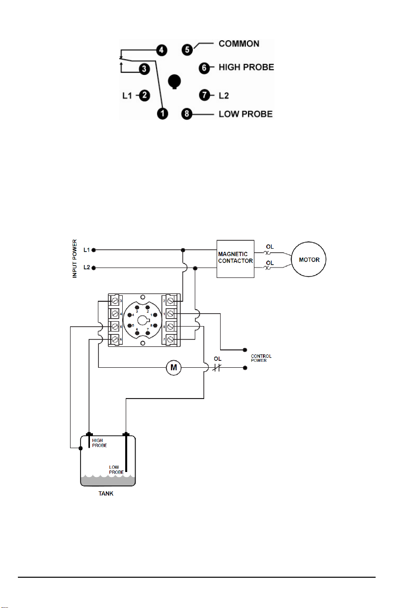
Figure 1: Pin-Out Diagram
Figure 2: Typical Pump Control Wiring Diagram
© 2009 SymCom, Inc. All Rights Reserved 3
Page 4

SETTINGS
Figure 3: Selectivity and Mode Selection
Use the adjustment knob shown in Figure 3 to set the mode of operation and the sensitivity threshold
for the probes. Set the sensitivity from 4.7k to 100k on the left half of the dial for pump-down
applications. Set the sensitivity from 4.7k to 100k on the right half of the dial for pump-up
applications
2
.
OPERATION
Apply power to the system. The green run light will come on if the relay has been energized.
The PumpSaver
®
is equipped with a debounce time delay. The PumpSaver® will wait for the time
delay to complete before energizing/de-energizing the relay.
Pump-Up
3
The relay is energized when liquid is not detected at the low probe, regardless of the state of the
high probe. When the liquid level rises and liquid is detected at the low and high probes, the relay is
de-energized.
4
Pump-Down
The relay is energized when the liquid level rises and is detected at the low and high probes. When
the liquid level drops and no liquid is detected at the low probe, the relay is de-energized, regardless
of the state of the high probe.
2
Reducing the resistance setting will provide increased sensitivity to the presence of liquid.
3
When used with a single probe in a pump-up setting, the relay will energize the pump when no liquid
is detected by the probe and de-energize when liquid is detected by the probe.
4
When used with a single probe in pump-down setting, the relay will energize the pump when liquid is
detected by the probe and de-energize when liquid is not detected by the probe.
© 2009 SymCom, Inc. All Rights Reserved 4
Page 5

TROUBLESHOOTING
SYMPTOM
Device is not functional
LIGHT
PATTERN
N/A
SOLUTION
Verify that the product is wired properly. If
wiring is correct, then measure the line voltage
at terminals 2 and 7 on the octal base. If the
voltage is below the minimum listed in the
Specification Table for the model in use, the
PumpSaver
operate its internal electronics. Also check for
a valid input to the unit from the appropriate
probe. If the voltages and probe inputs are
correct but unit fails to function, call SymCom
at (800) 843-8848 or (605) 348-5580.
®
does not have enough power to
Green LED turns on, but
the pump does not run.
GREEN LED ON
The PumpSaver
®
has energized the internal
relay. Check the wiring to the motor’s magnetic
contactor coil. Verify all safeties and controls
are operating correctly.
© 2009 SymCom, Inc. All Rights Reserved 5
Page 6

DIMENSIONS
2.375”
(60.331)
BOTTOM
WITH OT08* SOCKET
SIDE
*The OT08 octal socket is 35mm DIN rail compatible. The use of an OT08 octal socket is required for
Model PC-XXX-LLC-CZ to qualify as a UL Listed device.
1.75”
(44.55)
4.125”
(104.65)
© 2009 SymCom, Inc. All Rights Reserved 6
Page 7

PUMPSAVER® PC-XXX-LLC-CZ SPECIFICATIONS
Functional Characteristics Debounce Time Delay 2 seconds Input Characteristics Line Supply Voltage
PC-100-LLC-CZ 95-120VAC PC-200-LLC-CZ 190-240VAC
Frequency 505/60Hz Probe Sense Voltage 5vdc Pulsed
Probe Sensitivity 4.7k to 100k Adjustable Output Characteristics Output Contact Rating
Pilot Duty 480VA @ 240VAC General Purpose 10A @ 240VAC
General Characteristics Environmental
Ambient Operating Temperature6 Relative Humidity 10-95%, non-condensing per IEC 68-2-3
Maximum Input Power 5 W Standards Passed
Electrostatic Discharge (ESD) IEC 61000-4-2, Level 3, 6kV contact, 8kV air Radio Frequency Immunity, Radiated 150 MHz, 10V/m Fast Transient Burst IEC 61000-4-4, Level 3, 2kV input power and controls Surge Immunity IEC IEC 61000-4-5, Level 4, 4kV line-to-line; Level 4, 4kV
ANSI/IEEE C62.41 Surge and Ring Wave Compliance to a level
Hi-Potential Test
Safety Marks UL listed (OT08 octal socket
required)
CE IEC 60947-6-2
Dimensions 1.750” H x 2.375” W x 4.125” D (with socket) Weight 9 oz. Enclosure Polycarbonate Mounting Method Plugs into OT08 Socket; DIN Rail or Surface Mount Wire Gauge 12-22 AWG Solid or Stranded Terminal Torque for P/N OT08 Socket 12 in. – lb
-40° to 70°C (-40° to 158°F)
line-to-ground; Level 2, 1kV probe inputs-toground
of 6kV line-to-line
Meets UL508
(2 x rated V +1000 V for 1 minute)
UL508 (File #E68520)
5
50 Hz will increase all delay timers by 20%
6
The ambient air temperature is the air temperature directly surrounding the product.
© 2009 SymCom, Inc. All Rights Reserved 7
Page 8

For warranty information, please see Terms and Conditions at
www.symcom.com
Visit us at www.symcom.com to see
our complete product listing!
Need something special?
Contact SymCom today
for your custom solution!
800-843-8848
© 2009 SymCom, Inc. All Rights Reserved 8
 Loading...