

Page 1
INSTALLATION
INSTRUCTIONS
Rapid City, SD, USA 07/09
MODEL PC-102CICI-DL
Revision B1
II_PC-102CICI-DL_B1
2880 North Plaza Drive, Rapid City, South Dakota 57702
(800) 843-8848 · (605) 348-5580 · fax (605) 348-5685
Page 2
BE SURE POWER IS DISCONNECTED PRIOR TO INSTALLATION!
V
A
FOLLOW NATIONAL, STATE AND LOCAL CODES.
READ THESE INSTRUCTIONS ENTIRELY BEFORE INSTALLATION.
SymCom’s PC-102CICI-DL is a dual seal-leak detector with two isolated form C output relays. The
input resistance threshold can be set from 4.7k – 100kΩ. A pulsed DC voltage is applied to the
probes, which prevents corrosion and build-up on the probes.
CONNECTIONS
1. Mount the PC-102 on 35mm DIN rail, or by installing two #6 – #8 screws into the surface
mounting holes provided.
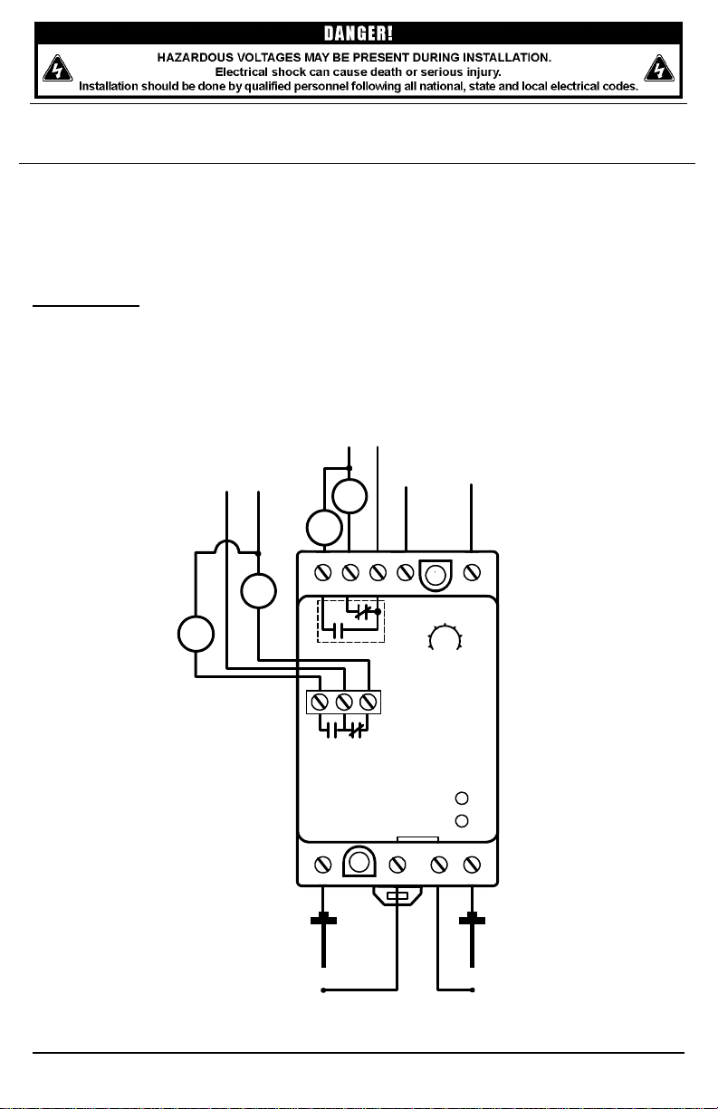
2. Connect inputs and outputs according to the typical wiring diagram below. Switches or
resistive probes can be used on the inputs. The PC-102 must be powered by 120VAC
connected to terminals 2 and 3.
24-240
C
24-240VAC
LOAD
3
LOAD
4
9
120VAC
53k
69k36k
4.7k 100k
85k20k
SENSITIVITY
LOAD
2
LOAD
1
1
RELAY 1
10 11 12
RELAY 2
PC-102CICI-DL
SEAL1
SEAL2
SEAL1 SEAL2
COM
5674
328
PROBE 2PROBE 1
Figure 1: Typical Wiring Diagram
(Relays are shown in their normal/non-energized states.)
© 2009 SymCom, Inc. All Rights Reserved 2
Page 3

SETTINGS
OPERATION
When the resistance measured at an input is greater than the sensitivity setting, the corresponding
output relay is de-energized—in its normal state. When the input resistance drops below the
sensitivity setting (water is detected), the associated output relay is energized. The input logic may be
reversed/inverted using DIP switches on the side of the device. Refer to Table 1 for setting the logic
for each input.
The PC-102CICI-DL can utilize either a 0.5-second or 2-second debounce time delay. The output
contact will not change states until a fault condition exists for this time period. Refer to Table 1 for
setting the debounce time delay for each input.
Red LEDs illuminate on the PC-102CICI-DL when the associated output relay is energized.
DIMENSIONS
”
Input
SEAL 1
SEAL 2
PC-102
”
DIP
Switch
S1 direct logic inverted logic
S2 0.5-sec. debounce 2-sec. debounce
S3 direct logic inverted logic
S4 0.5-sec. debounce 2-sec. debounce
Table 1: DIP Switch Settings
”
”
OFF ON
”
Figure 2: Dimensions
© 2009 SymCom, Inc. All Rights Reserved 3
Page 4

Model PC-102CICI-DL SPECIFICATIONS
Functional Characteristics
Adjustments
Sensitivity 4.7k – 100kΩ
Input Logic Direct or inverted
Debounce Time Delay 0.5 or 2 seconds
Probe Voltage Pulsed 5V DC
Input Characterisitcs
Voltage Range 120VAC
Frequency 50/60 Hz
Output Characteristics
Pilot Duty 180VA @ 120VAC, C150
General Purpose 5Amps @ 240VAC
Depluggable Connector (included) Phoenix Contact - Series MSTB plugs (or
General Characteristics
Weight 9 oz.
Torque 6 in.-lbs. (max.)
Wire AWG 12–20 AWG
Safety Marks
UL Listed UL508 (File #E68520)
cUL C22.2 No. 14
Standards Passed
Electrostatic Discharge (ESD)
Radio Frequency Immunity,
Radiated
Fast Transient Burst
Environmental
Temperature Range -20 to 55° C
For warranty information, please see Terms and Conditions at
equivalent)
IEC 61000-4-2, Level 3, 6 kV contact, 8 kV air
IEC 61000-4-2, Level 3, 10V/m
IEC 61000-4-4, Level 3, 4 kV input power
2 kV inputs/outputs
www.symcom.com
you’re looking for?
Visit us at www.symcom.com to see
our complete product listing!
Can’t find what
SymCom designs and manufactures
custom control boards too.
Call us for details!
© 2009 SymCom, Inc. All Rights Reserved 4
 Loading...