

Page 1
MP8000
MOTOR PROTECTION RELAY
Instruction Manual
REVISION 0-A-030818
Copyright © 2018 Littelfuse. All rights reserved.
Page 2

Page A
MP8000 Motor Protection Relay
REV. 0-A-030818
All brand or product names appearing in this document are the trademark or registered
trademark of their respective holders. No Littelfuse trademarks may be used without written
permission. Littelfuse products appearing in this document may be covered by U.S. and
Foreign patents.
Littelfuse, Inc. reserves all rights and benefits afforded under federal and international
copyright and patent laws in its products, including without limitation software, firmware, and
documentation.
The information in this document is provided for informational use only and is subject to
change without notice. Littelfuse, Inc. has approved only the English language document.
Page 3

MP8000 Motor Protection Relay
TABLE OF CONTENTS
Page 1
REV. 0-A-030818
SECTION PAGE
1 Preface .......................................................................................3
1.1 Manual Overview .................................................................3
1.2 Safety Information ...............................................................3
1.2.1 Dangers, Warnings, and Cautions ...........................3
1.2.2 Safety Symbols ........................................................3
1.2.3 Warnings, Cautions, and Notes ..............................4
1.2.4 Compliance Approvals .............................................4
1.3 General Information .............................................................4
1.3.1 Typographic Conventions .........................................4
1.3.2 Examples ..................................................................4
1.3.3 Product Labels .........................................................4
1.3.4 Instructions for Cleaning and Decontamination ......4
2 Introduction and Specifications ...........................................5
2.1 Overview ..............................................................................5
2.2 Features ................................................................................5
2.2.1 Standard Protection Features ..................................5
2.2.2 Monitoring Features ................................................5
2.2.3 Communications and Control ..................................5
2.2.4 Connectivity .............................................................5
2.2.5 Security ....................................................................5
2.2.6 Power Supply ...........................................................5
2.3 Models, Options, and Accessories ......................................5
2.3.1 Models .....................................................................5
2.3.2 Accessories ..............................................................5
2.4 Applications .........................................................................6
2.5 Getting Started .....................................................................7
2.5.1 Powering the Relay ..................................................7
2.5.2 Establishing Communication ...................................7
2.6 Specifications .......................................................................7
2.6.1 Compliance ..............................................................7
2.6.2 General ....................................................................7
2.6.3 Type Tests ................................................................8
2.6.4 Current Transformers (CTs) ......................................9
2.6.5 Relay Elements ........................................................9
2.6.6 Metering ................................................................11
3 Installation ..............................................................................12
3.1 Overview ............................................................................12
3.2 Phone Application ..............................................................12
3.3 Relay Placement .................................................................12
3.3.1 Physical Location ...................................................12
3.4 Relay Features and Connections ........................................12
3.4.1 Relay Mounted on DIN Rail ...................................13
3.4.2 Relay Mounted on Solid Surface or Panel ............14
3.5 Relay Connections ..............................................................14
3.5.1 Terminal Block Connections ..................................14
3.5.2 Wire Sizes ..............................................................14
3.5.3 Voltage Connections (L1, L2, L3)............................14
3.5.4 Power Supply Connections (A1, A2) ......................15
3.5.5 Relay Contacts (1 Form C and 1 Form A)
Connections ...........................................................15
SECTION PAGE
3.5.6 Current Connections .............................................15
3.5.7 Power Supply Connections (A1, A2) ......................15
3.5.8 Inputs, PTC, ZSCT Connections .............................15
3.5.9 Input Connections (I.1) ...........................................15
3.5.10 PTC Connections (T1, T2) .......................................16
3.5.11 Zero-Sequence Current Transformer (ZSCT)
(Z1, Z2) (for Ground Fault detection) ......................16
3.5.12 Connecting to a PC ................................................16
3.5.13 Connecting to the Littelfuse MP8000 App ............16
3.6 AC/DC Control Connection Diagrams ................................16
3.6.1 Three-Phase Motor under 100 FLA with
optional ZSCT and PTC connected ........................16
3.6.2 Three-Phase Motor over 100 FLA ..........................17
3.6.3 Single-Phase Applications .....................................18
4 Littelfuse MP8000 Smartphone and Tablet App ...............19
4.1 Overview ............................................................................19
4.2 Installing the Android App .................................................19
4.3 Installing the iPhone App ...................................................19
4.4 Running the Littelfuse MP8000 App ..................................19
4.5 Advertising Page ................................................................19
4.6 Configuration Pages ...........................................................20
4.7 Configuration Basic Page (Protective Features) .................21
4.7.1 Low Voltage (LV) ....................................................21
4.7.2 High Voltage (HV)...................................................22
4.7.3 Voltage Unbalance (VUB).......................................22
4.7.4 Overcurrent (OC) ....................................................22
4.7.5 Undercurrent (UC) ..................................................22
4.7.6 Current Unbalance (CUB) .......................................22
4.7.7 Trip Class (TC) ........................................................22
4.7.8 Restart Delay Zero (RD0) .......................................22
4.7.9 Restart Delay One (RD1) ........................................23
4.7.10 Restart Delay Two (RD2) ........................................23
4.7.11 Restart Delay Three (RD3) .....................................23
4.7.12 Undercurrent Restart Attempts (RU) .....................23
4.7.13 Other Faults Restart Attempts (RF) ........................23
4.7.14 Basic Settings Default Values ...............................23
4.8 Configuration Advanced Page (Protective Features) ..........23
4.8.1 Current Transformer Ratio (CT) ..............................23
4.8.2 Potential Transformer Ratio (PT) ............................24
4.8.3 Undercurrent Trip Delay (UCTD) ............................24
4.8.4 Linear OC Trip Delay (LINTD) .................................24
4.8.5 Ground Fault Trip Current (GFTC) ...........................24
4.8.6 Ground Fault Trip Delay (GFTD) .............................24
4.8.7 Low Power Trip Limit (LKW) ..................................24
4.8.8 High Power Trip Limit (HKW) .................................24
4.8.9 High Power Trip Delay (HPTD) ...............................25
4.8.10 Stall Percentage (STLP) .........................................25
4.8.11 Stall Trip Delay (STTD) ...........................................25
4.8.12 Stall Inhibit Delay (STID) .......................................25
4.8.13 Advanced Settings Default Values ........................25
Page 4

MP8000 Motor Protection Relay
Page 2
REV. 0-A-030818
SECTION PAGE
4.8.14 Hardware Configuration Fields
Single-Phase Motor (SPM) ....................................25
4.8.15 Communication Settings ........................................26
4.8.16 RTD Module ...........................................................26
4.8.17 Change Device Name ............................................26
4.8.18 Change Password ..................................................26
4.8.19 Reset Password .....................................................26
4.9 Real-Time Page (Measurements & Monitoring) ................26
4.9.1 Device ID ................................................................26
4.9.2 Reset Relay ............................................................26
4.9.3 System Status ........................................................26
4.9.4 Active Timer ...........................................................26
4.9.5 Line-to-Line Voltage...............................................27
4.9.6 Voltage Unbalance.................................................27
SECTION PAGE
4.9.7 Line Current ...........................................................27
4.9.8 Current Unbalance .................................................27
4.9.9 Power .....................................................................27
4.9.10 Power Factor ..........................................................27
4.9.11 Run-Time ................................................................27
4.9.12 Start Count .............................................................27
4.9.13 Thermal Capacity ...................................................27
4.9.14 Fault Page ..............................................................27
4.10 Time Settings ...................................................................28
4.11 Real-Time Page (Measurements & Monitoring) ..............28
4.11.1 DHCP Assigned IPv4 Address ................................28
4.11.2 Point to Point IP Address Assignment (no
DHCP) .....................................................................28
4.11.3 Setting a Static IP Address ....................................28
5 PC Interface ............................................................................31
6 Troubleshooting .....................................................................32
6.1 Overview ............................................................................32
7 Ground Fault Testing Procedure .........................................33
Page 5

MP8000 Motor Protection Relay
DANGER
DANGER
WARNING
CAUTION NOTE:
DANGER
WARNING
1. PREFACE
Page 3
REV. 0-A-030818
1.1 Manual Overview
The MP8000 Motor Management Relay Instruction
Manual describes common aspects of motor relay
application and use. It includes the necessary
information to install, set, test, and operate the relay.
An overview of each manual section and topics follows:
1. PREFACE
Describes the manual organization and conventions
used to present information.
2. INTRODUCTION AND SPECIFICATIONS
Describes the basic features and functions of the
MP8000; lists the relay specifications.
3. INSTALLATION
Describes how to mount and wire the MP8000;
illustrates wiring connections for various applications.
4. SMARTPHONE/TABLET APPLICATION
Describes the features, installation methods, and
types of help available with the Littelfuse MP8000
App, including setting the relay, meter and monitoring,
control, and fault retrieving.
5. PC INTERFACE
Describes the features, installation methods, and
types of help available with the Littelfuse MP8000
Software, including setting the relay, meter and
monitoring, control, and events retrieving.
6. TROUBLESHOOTING
Describes common causes for various trip/fault
conditions.
7. GROUND FAULT TESTING
1.2 Safety Information
1.2.1 Dangers, Warnings, and Cautions
This manual uses three kinds of hazard statements,
defined as follows:
Indicates an imminently hazardous situation that, if not
avoided, will result in death or serious injury.
Indicates a potentially hazardous situation that, if not
avoided, could result in death or serious injury.
Indicates a potentially hazardous situation that, if not
avoided, may result in minor or moderate injury or
equipment damage.
1.2.2 Safety Symbols
The following symbols are often marked on Littelfuse
products.
CAUTION
Refer to accompanying documents.
Earth (ground)
Protective earth (ground)
Direct current
Alternating current
Both direct and alternating current
Instruction manual
Page 6
MP8000 Motor Protection Relay
DANGER
WARNING
DANGER
WARNING
CAUTION NOTE:
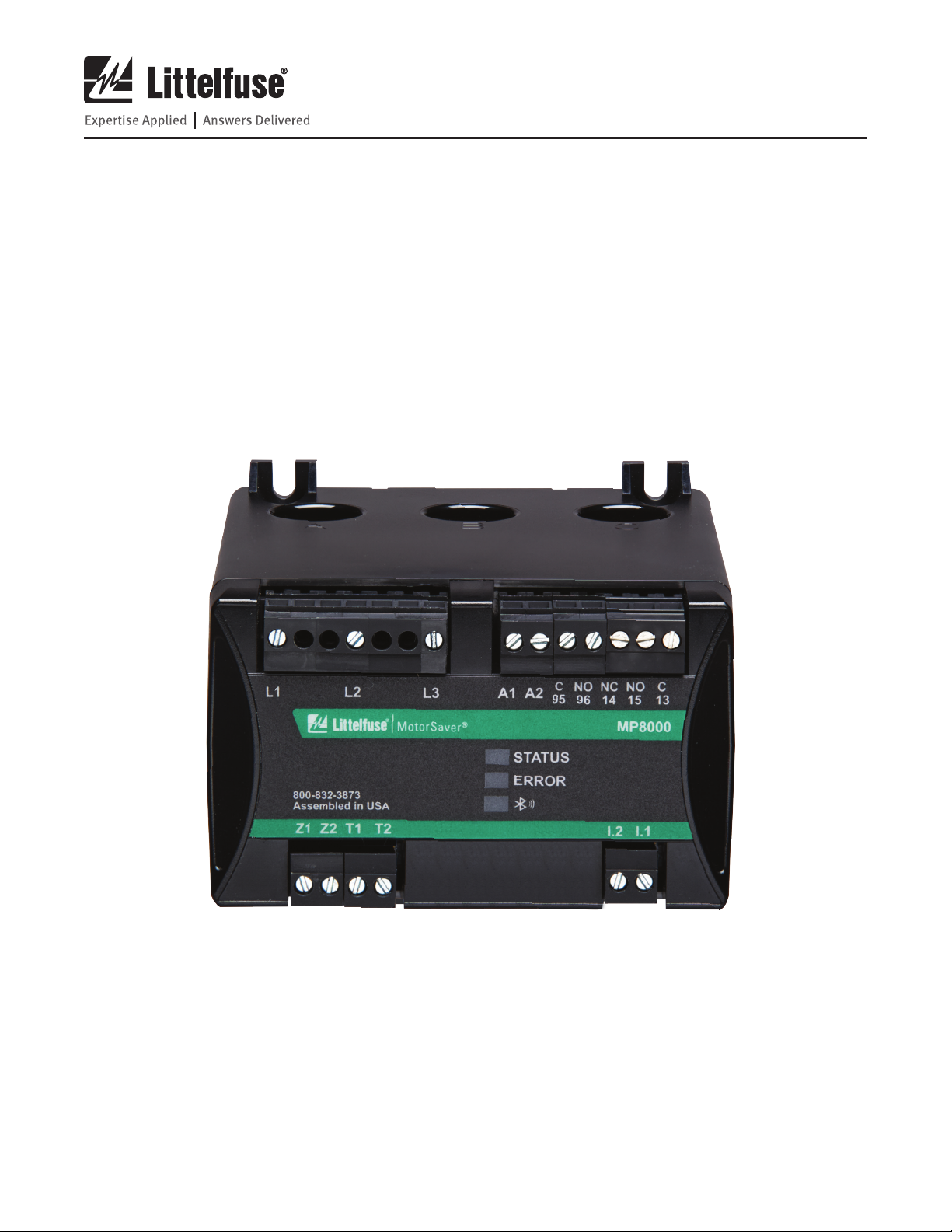
MP8000
Control Power Input: 90-265VAC
Advanced Motor Protection Overload Relay
Voltage Input (L-to-L): 90-690VAC 50/60Hz 1Ø/3Ø
Input Current: 0.5-100A Direct; 100-1000A*
Contact Rating: 5A @ 240VAC, B300
Pair Code Password: 966352
Setpoint Default Password: admin
MAC Address: 00:21:6F:00:41:F5
*With External CT’s Date Code: 2018/06
Contains FCC ID: TFB-1002
Contains IC: 5969A-1002
Patent Pending
IND. CONT. EQ.
LISTED
®
Page 4
REV. 0-A-030818
1.2.3 Warnings, Cautions, and Notes
Use of this equipment in a manner other than specified
in this manual can impair operator safety safeguards
provided by this equipment.
Installation should be done by qualified personnel
following all national, state and local electrical codes.
Have only qualified personnel service this equipment.
If you are not qualified to service this equipment, you
can injure yourself or others, or cause equipment damage.
Equipment components are sensitive to electrostatic
discharge (ESD). Undetectable permanent damage
can result if you do not use proper ESD procedures.
Ground yourself, your work surface, and this equipment
before installing this equipment. If your facility is not
equipped to work with these components, contact
Littelfuse about returning this device and related
Littelfuse equipment for service.
1.3 General Information
1.3.1 Typographic Conventions
You can communicate with the MP8000 in three ways.
• Use the Littelfuse MP8000 app, iPhone/iPad
or Android. The MP8000 uses Bluetooth 4.0
(Bluetooth Low Energy - BLE). The smartphone or
tablet must have BLE to connect to the MP8000.
• Use the Ethernet port connected to a PC (via
network) with Littelfuse MP8000 Software installed.
• Use the Ethernet port connected to a network
and create a Modbus TCP or Ethernet/IP program
using the MP8000 memory map.
1.3.2 Examples
This instruction manual uses several example
illustrations and instructions to explain how to
effectively operate the MP8000. These examples
are for demonstration purposes only; the firmware
identification information or settings values included
in these examples may not necessarily match those in
the current version of your MP8000.
1.3.3 Product Labels
The MP8000 label is shown below. The label is located
on the right side panel of the product.
Product Compliance Label for the MP8000
NOTE: This device is shipped with default passwords.
Default passwords should be changed to private
passwords at installation. Failure to change each
default password to a private password may allow
unauthorized access. Littelfuse shall not be responsible
for any damage resulting from unauthorized access.
1.2.4 Compliance Approvals
1.3.4 Instructions for Cleaning and
Decontamination
Use a mild soap or detergent solution and a damp
cloth to carefully clean the MP8000 chassis when
necessary. Avoid using abrasive materials, polishing
compounds, and harsh chemical solvents (such as
xylene or acetone) on any surface of the relay.
Page 7

MP8000 Motor Protection Relay
2. INTRODUCTION AND SPECIFICATIONS
Page 5
REV. 0-A-030818
2.1 Overview
The MP8000 Motor Protection Relay is designed
to protect three-phase or single-phase motors. The
basic relay provides locked rotor, overload, overtemperature, and unbalance protection. Voltage-based
protection elements are standard. Additionally, the
relay includes inverse time-over current elements
suitable for overload protection. All relay models
provide monitoring functions.
The relay operates as a fail-safe device. This means
when the voltage is within the programmed limits,
the relay will energize—the NO contact will close.
When the unit loses power or senses a fault condition,
the relay will de-energize and contacts will return to
their original state. Once the unit has been installed
and programmed, the unit is ready to operate. Once
acceptable voltage is applied and the RD0 timer
expires, the relay will energize—the NO contact
will close.
This manual contains the information needed to install,
set, test, operate, and maintain any MP8000. You need
not review the entire manual to perform specific tasks.
2.2 Features
2.2.1 Standard Protection Features
• Overload (Overpower) (49)
• Underload (Underpower) (37P)
• Undercurrent (Load Loss) (37)
• Current Unbalance/Phase Loss (46)
• Overcurrent (Load Jam) (51)
• Ground Fault—Zero-Sequence (50Ns)
• Manual Motor Reset input
• Phase Time-Overcurrent (51)
• Phase Reversal (47), voltage based
• Voltage Unbalance (47)
• Motor Starting/Running
• Start Motor Run-Timer
• Thermal Capacity Utilization (TCU)
• Contactor Failure Protection
• Positive Temperature Coefficient (PTC) OverTemperature Switching Thermistor (49)
• Undervoltage (27)
• Overvoltage (59)
• Power Elements (32)
2.2.2 Monitoring Features
• Event Summaries that contain relay ID, date and
time, trip cause, and current/voltage magnitudes
• Sequential Multiple Events Recorder (SER)
• Power Factor
• Running times
• Number of starts
• A complete suite of accurate metering functions
• Thermal Capacity Used
2.2.3 Communications and Control
• Ethernet Modbus TCP, Ethernet FTP, Ethernet/IP
• Bluetooth 4.0 (Bluetooth Low Energy - BLE)
2.2.4 Connectivity
• Voltage: direct connection (as high as 690 VAC,
line-to-line); three-wire delta, open-delta or singlephase connected Potential Transformers
• Current: Built-in pass-through current transformers
for 0.5-100A phase current measurements
• External current transformer inputs for >100A
phase current measurements
• Zero-Sequence Ground Fault CT input
• Positive Temperature Coefficient Input (PTC)
• Digital Outputs: one Form-A output contacts, one
Form-C output contact
• Digital Inputs: Externally wetted to 110/240 VAC
2.2.5 Security
• Pairing and Setpoint change pass codes on side
labels, unique to each MP8000
2.2.6 Power Supply
• Wide input range 85-264VAC
2.3 Models, Options, and Accessories
2.3.1 Models
Complete ordering information is not provided in this
instruction manual. See the latest MP8000 Model
Option Table at www.littelfuse.com.
2.3.2 Accessories
Contact your Technical Service Center or the Littelfuse
factory for additional detail and ordering information
for the following accessories/options:
• Zero-Sequence CTs
Page 8
MP8000 Motor Protection Relay
Page 6
REV. 0-A-030818
2.4 Applications
Section 3: Installation includes connection diagrams
for various applications. The following is a list of
possible application scenarios:
• With or without external current and/or
voltage transformer
• Full voltage non-reversing (FVNR) starter
(across the line)
• Forward/reverse starter – Accomplished by
placing the MP8000 “above” the forward and
reverse contactors.
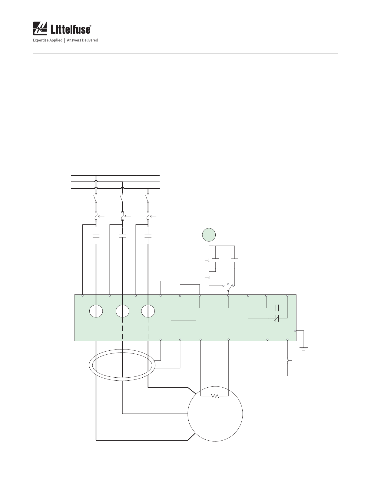
PHASE A
PHASE B
PHASE C
90 - 690 VAC
0.5 - 100A (100A+ using external CTs)
Figure 2.1 shows across-the-line starting AC
connections with optional ZSCT and PTC. Refer to
Section 3: Installation for additional applications and
the related connection diagrams.
FROM A1
C
AUX VOLTAGE
SUPPLY
85 – 264 VAC
L1 L3L2 A2/L
A
B
ZERO-SEQUENCE
CURRENT
TRANSFORMER
(OPTIONAL)
A1/N
C
MP8000
Z1
START
STOP
C
(95)
Z2 T1
C
HAND
NO
(96)
PTC
(OPTIONAL)
M
OFF
PILOT
AUTO
NO
NC
(15)
(14)
T2
C
(13)
I.2 I.1
.
FROM A2
PE
RESET
Figure 2.1 AC Connections - Across-the-Line Starting
Page 9

MP8000 Motor Protection Relay
Page 7
REV. 0-A-030818
2.5 Getting Started
Understanding basic relay operation principles and
methods will help you use the MP8000 effectively.
This section presents the fundamental knowledge
you need to operate the MP8000, organized by task.
These tasks help you become familiar with the relay
and include the following:
• Powering the relay
• Establishing communication
• Inputting configuration settings
• Checking relay status
Perform these tasks to gain a fundamental understanding
of relay operation.
2.5.1 Powering the Relay
Power the MP8000 with 85-264 VAC.
• Connect the earth ground lead; see figure 2.1 for
Power Supply Connections.
• Once connected to power, the relay does an
internal self-check , flashing all LEDs. After the
self-check, either the green STATUS LED, or the
red ERROR LED will be illuminated. If the green
STATUS LED is on, the relay status is “ok”, and
the control relay will be closed. If any condition
is present that will not allow the control relay to
close, or the relay is tripped (and/or restarting), the
red ERROR LED will be illuminated and the green
STATUS LED will be off.
2.5.2 Establishing Communication
The standard MP8000 has a Bluetooth Low Energy
(BLE) interface via Littelfuse MP8000 app and an
Ethernet port via Littelfuse MP8000 Software. When
the MP8000 has successfully connected to a Bluetooth
Low Energy enabled device running the MP8000 app,
the blue LED is illuminated.
See Section 4: Littelfuse MP8000 Smartphone and
Tablet App for more information on app installation and
operation.
See Section 5: PC Interface for more information on
MP8000 Software installation and operation.
2.6 Specifications
NOTE: Motors/loads with FLA > 100 amps must use external CTs. You
must use CTs that have a rated secondary current of 5 amps (examples
50:5, 100:5, 200:5, etc.).
2.6.1 Compliance
CE Mark: EMC Directive Low-Voltage
Directive
IEC: IEC 60947-1 Edition 5.2 (UL 60947),
IEC 60947-8-1, EC 60947-4-1
UL, cUL: UL-1053, C.22.2 No. 14
RCM: AS/NZS 4417.1
AS/NZS 4417.2
2.6.2 General
AC Current Inputs—Phase
Full Load Amperage (FLA): 0.5–100.0 A
(> 100 A with external CTs)
Rated Frequency: 50/60 Hz
Burden (Per Phase): 0.0025 VA @ 30 A
Zero-Sequence CT Current (IN)
Zero-Sequence CT Ratio: 100:1
Input Rated Current Range: 0.010–50.0 mA
Input Rated Continuous
Thermal Current: 150 mA
One Second Thermal
Current: 1.5 A
Saturation Current: 5-50 mA
Burden: 0.09 VA at 50 mA
AC Voltage Inputs (Line-to-Line)
Rated Operating
Voltage (Ue): 90–690 VAC
Rated Continuous Voltage: 800 VAC
Rated Frequency: 45/65 Hz
Burden: < 0.72 VA @ 690 VAC
Power Supply
Rated Supply Voltage: 85-264 VAC
Power Consumption: < 5 W
Interruptions: 20 ms minimum
Output Contacts
General
Mechanical Durability: 100,000 no load operations
Pickup/Dropout Time: < 10 ms
(coil energization to contact closure)
AC Output Ratings for relays;
CONTROL (Form A),
ALARM (Form C)
Contact Rating
Designation: B300
(B = 5 A, 300 = rated insulation voltage)
Maximum Operational
Voltage: 250 VAC
Maximum Operational
Current: 5 A
Rated Frequency: 50/60 ±5 Hz
Electrical Durability Make
VA Rating: 3600 VA
Electrical Durability Break
VA Rating: 360 VA
Page 10
MP8000 Motor Protection Relay
Page 8
REV. 0-A-030818
Optoisolated Control Inputs
(Externally Wetted to 110/240 VAC)
Maximum Current Draw: 5 mA @ 110 VAC, 10 mA @ 240 VAC
Rated Impulse Withstand
Voltage (Uimp): 4000 V
Pickup Time: < 200 ms
Dropout Time: > 1000 ms
Frequency and Phase Rotation
System Frequency: 50, 60 Hz
Phase Rotation: ABC, ACB
Frequency Tracking: 45–65 Hz
Time-Code
Format: Unix Time (UTC)
Accuracy (Clock Drift): 10 minutes per year, typically
Communications Ports
Ethernet Port: Single, 10/100BASE-T copper
(RJ45 connector)
Communications Protocols
Modbus TCP, FTP, Ethernet/IP
Operating Temperature
Rated Operating Range: -40° to +70°C (-40° to +158°F)
Rated Storage Range: -40° to +85°C (-40° to +185°F)
Operating Environment
Pollution Degree: 3
Overvoltage Category: III (up to 300 VAC to earth)
II (up to 600 VAC to earth)
Atmospheric Pressure: 80–110 kPa
Relative Humidity: 5–95%, non-condensing
Maximum Altitude
Without Derating: 3000 m
(Consult Factory for Higher Altitude Derating)
Dimensions
Height: 74.4 mm (2.9 in.)
Width: 103.6 mm (4.1 in.)
Depth: 121.7 mm (4.8 in.)
Weight 0.4 kg (0.9 lbs)
Terminal Connections
Compression Plug
(Black, 5.08mm spacing)
Tightening Torque
Maximum: 0.62 Nm (5.5 in-lb)
Earth Ground Lug Tightening
Torque Maximum: 0.89 Nm (7.9 in-lb)
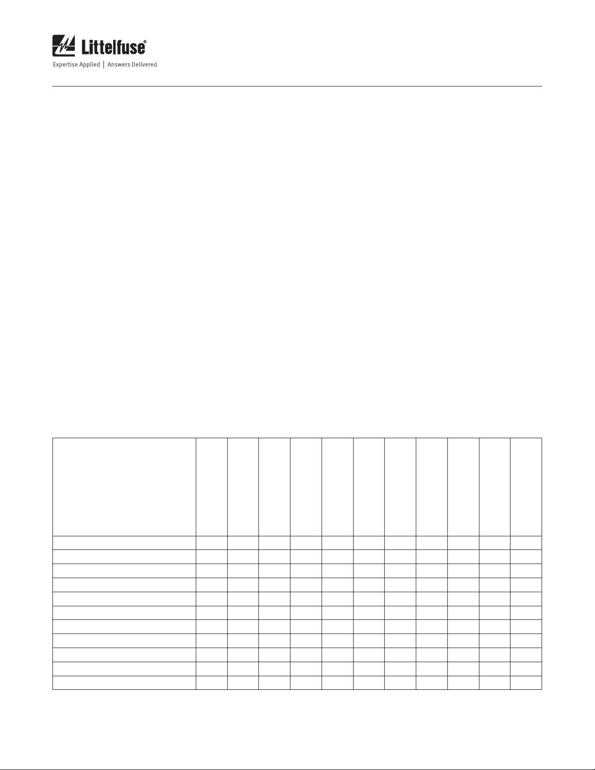
2.6.3 Type Tests
Dielectric Strength and Impulse Tests
Dielectric (HiPot): (See Table 2.1)
Table 2.1 MP8000 Insulation Between Inputs And Outputs
Dielectric Strength (Volts)
Measuring Input (L1, L2, L3)
Measuring Input (L1, L2, L3) X 2380 2380 2380 2380 2380 2380 2380 2380 2380 2380
Power Supply (A1, A2) 2380 X 1528 1528 1528 1528 X 1528 1528 1528 1528
Relay-Alarm (C (13), NO (15), NC (14)) 2380 1528 X 1528 1528 1528 1528 1528 1528 1528 1528
Relay-Control (C (95), NO (96)) 2380 1528 1528 X 1528 1528 1528 1528 1528 1528 1528
ZSCT (Z1, Z2) 2380 1528 1528 1528 X 1528 1528 X 1528 1528 1528
PTC (T1, T2) 2380 1528 1528 1528 1528 X 1528 1528 1528 1528 1528
Digital In (I.1) 2380 X 1528 1528 1528 1528 X 1528 1528 1528 1528
Ground Terminal 2380 1528 1528 1528 X 1528 1528 X 1528 1528 1528
RS485 2380 1528 1528 1528 1528 1528 1528 1528 X 1528 1528
CAN Bus 2380 1528 1528 1528 1528 1528 1528 1528 1528 X 1528
Ethernet 2380 1528 1528 1528 1528 1528 1528 1528 1528 1528 X
Power Supply (A1,A2)
Relay-Alarm
(C (13), NO (15), NC (14))
Relay-Control
(C (95), NO (96))
ZSCT (Z1, Z2)
PTC (T1, T2)
Digital In (I.1)
Ground Terminal
RS485
CAN Bus
Ethernet
Page 11
MP8000 Motor Protection Relay
Page 9
REV. 0-A-030818
RFI and Interference Tests
Electrostatic Discharge (ESD): IEC 61000-4-2, Level 3, 6kV contact,
8kV air
Radio Frequency Immunity
(RFI), Conducted : IEC 61000-4-6, Level 3 10V/m
Radio Frequency Immunity
(RFI), Radiated: IEC 61000-4-3, Level 3 10V/m
Fast Transient Burst: IEC 61000-4-4, Level 3,
3.5kV input power
Surge: IEC 61000-4-5, Level 3, 2kV line-to-
line; Level 4, 4kV line-to-ground
FCC Rating: Part 15.107 for emissions, Part
15.247 for intentional radiators
Fault Events Recorder
Number of faults stored: 1,000 (most recent faults)
Time-Stamp Resolution: 1 second
Time-Stamp Accuracy
(With Respect to
Time Source): ±1 second
2.6.4 Internal Current Transformers (CTs)
Our Full-Load Current
(FLA) Limits: 0.5–100.0 A
NOTE: Motors/loads with FLA > 100 amps must use external CTs. You
must use CTs that have a rated secondary current of 5 amps (examples
50:5, 100:5, 200:5, etc.).
2.6.5
Relay Elements
See section Littelfuse MP8000 Smartphone and Tablet App >
Configuration Page for details on programming relay behavior.
The numbers in parenthesis in the following specifications are
ANSI device numbers.
Phase-to-Phase Under Voltage (27)
NOTE: Motors/loads operating at voltages higher than 690 VRMS must
use external PTs.
Parameter Name: Low Voltage (LV)
Enable/Disable: No disable available
Setting Range: 90 V
minimum
RMS
Accuracy: ±1% of setting ±2 VRMS
High Power (49)
Parameter Name: High Kilo-Watt (HKW)
Enable/Disable: Default is disabled
Setting Range: Not limited
Accuracy: ±5% of setting ±5 Watts
Under Power (37P)
Parameter Name: Low Kilo-Watts (LKW)
Enable/Disable: Default is disabled
Setting Range: Not limited
Accuracy: ±5% of setting ±5 Watts
Undercurrent (Load Loss) (37)
Parameter Name: Under Current (UC)
Enable/Disable: Default is enabled
Setting Range: Not limited; Suggest 0.75–0.95 • FLA
Accuracy: ±2% of setting ±0.01 ARMS
Pickup/Dropout Time: 1 second + programmable delays
Current Unbalance and Phase Loss (46)
Parameter Name: Current Unbalance (CUB)
Enable/Disable: Default is enabled
Setting Range: Not limited; Default 5; Suggest
5–45%
Accuracy: ±5% of setting
Maximum Pickup/
Dropout Time: See Table 2.2. Additional delays for
motor startup may apply
Table 2.2 CUB Trip Time, CUTD=30
MEASURED VALUE OF CURRENT UNBALANCE TRIP TIME
CUB setting
CUB setting + 1% 15 seconds
CUB setting + 2% 10 seconds
CUB setting + 3% 8 seconds
CUB setting + 4% 6 seconds
CUB setting + 5% 5 seconds
CUB setting + 6% 4 seconds
CUB setting + 10% 3 seconds
CUB setting + 15% or more
30 seconds
2 seconds
Example:
CUB setting = 5% If measured value of current
unbalance is 6% the MP8000 will
trip in 15 seconds
Voltage Unbalance (47)
Parameter Name: Voltage Unbalance (VUB)
Enable/Disable: Default is enabled
Setting Range: Not limited; Default 5%;
Suggest 2%-25%
Accuracy: ±1% of setting ±2 VRMS
Phase Reversal (47)
NOTE: This condition is detected prior to motor startup. After startup this
condition is not monitored.
Rotation Direction: Programmable; Default ABC
Page 12

MP8000 Motor Protection Relay
Page 10
REV. 0-A-030818
Incomplete Sequence (Load Jam/Stall) (48)
Parameter Name: Stall Percentage Current (STLP)
Enable/Disable: Default is disabled
Setting Range: Not limited; Suggest is 400% of OC
Accuracy: ±2% of setting
Maximum Pickup/
Dropout Time: Programmable
(Stall Time Delay seconds)
PTC Over-Temperature (49)
Type of Control Unit: IEC 60947-8, mark A
Max. Number
of Thermistors: Must adhere to the limits below
Over Temp Trip Resistance: ≥ 1650 ± 80 ohms
Reset Range: ≥ 25 ohms and ≤ 1500 ohms
Short circuit Detection
Resistance: ≤ 20 ± 5 ohms
Maximum Cold Resistance: 1500 ohms
Ground Fault - Residual Method (Zero-Sequence)(50N)
Best protection is with a resistively grounded system
Parameter Name: Ground Fault Trip Current (GFTC)
Ground Fault Trip Delay (GFTD)
GFTC Setting Range: GFTC = 0 is OFF (disabled);
Default is disabled.
Suggested Range is 0.20–4.5 A
Accuracy: ±2% of setting ±0.01 A
RMS
Time Delay: Class I operation 0.5 – 1.0 seconds
Class II operation 1.1 – 5.0 seconds
Values above 5 seconds are
non-standard
Timing Accuracy: ±250 ms
Overcurrent (51)
Parameter Name: Linear Overcurrent Trip Delay
(LINTD)
Enable/Disable: Default is disabled
Setting Range: Not limited; Default is 5 Seconds; 1
second minimum
Accuracy: ±2% of setting ±0.1 second
Figure 2.2 Overcurrent Trip Curves
Page 13

MP8000 Motor Protection Relay
Page 11
REV. 0-A-030818
Inverse-Time Overcurrent (51)
Parameter Name: Trip Class (TC)
Enable/Disable: Default is enabled
Setting Range: Not limited; common values 5, 10,
15, 20, 30
Accuracy: See Figure 2.2; ±2% of setting
±0.1 second
Phase-to-Phase Overvoltage (59)
NOTE: Motors/loads operating at voltages higher than 690 VRMS must
use external PTs.
Parameter Name: High Voltage (HV)
Enable/Disable: No Disable available
Setting Range: Not limited
Accuracy: ±1% of setting ±2 V
Timers (See section 4.7 for details on RD0-RD3)
Setting Range: Various
Accuracy: ±0.5% of setting ±1 second
2.6.6 Metering
Accuracies are specified at 20°C, 50 or 60 Hz nominal frequency,
AC currents within 0.5 – 100 ARMS, and ac voltages within
90–690 VRMS unless otherwise noted.
Line-to-Line Voltages: ±1% of reading ±0.5 VRMS
Voltage Unbalance (%): ±1% of reading
Phase Currents: ±2% of reading ±0.05 ARMS
Current Unbalance (%): ±2% of reading
Real Power (kW): ±5% of reading for 0.10 < pf < 1.00
Power Factor: ±3% of reading
Thermal Capacity Used: ±5% of reading
THE FOLLOWING ITEMS ARE ONLY AVAILABLE
THROUGH NETWORK ACCESS OF THE MEMORY MAP:
System Frequency: ±0.1 Hz of reading for frequencies
within 45–65 Hz (V1 > 90 V)
IG (Ground Current): ±2% of reading ±0.001 ARMS
Page 14

MP8000 Motor Protection Relay
3. INSTALLATION
Page 12
REV. 0-A-030818
3.1 Overview
The first steps in applying the MP8000 Motor
Protection Relay are installing and connecting the
relay. This section describes common installation
features and requirements. To install and connect the
relay safely and effectively, you must be familiar with
relay configuration features and options. You should
carefully plan relay placement, cable connections, and
relay communication.
This section contains drawings of typical AC and DC
connections to the MP8000. Use these drawings
as a starting point for planning your particular relay
application.
3.2 Smartphone/Tablet Application
The installation details for the Littelfuse MP8000 app
are presented in Section 4. There are two options:
• Android (supports versions 4.3 and higher)
• iOS (supports versions 9.0 and higher)
Universal Control Power
85 – 264 VAC
Relay Output
Control/Alarms
3.3 Relay Placement
Proper placement of the MP8000 helps to ensure
years of trouble-free motor management. Use the
following guidelines for proper physical installation of
the MP8000.
3.3.1 Physical Location
Mount the MP8000 in a sheltered indoor environment
(a motor control center drawer or bucket, a building,
or an enclosed cabinet) that does not exceed the
temperature, humidity, and IP ratings for the relay.
See environmental specifications in section 2.6.
3.4 Relay Features and Connections
Figure 3.1 shows the relay features and connections
to cover all the ordering options. The wiring terminal
blocks are labeled as shown on the relay.
Built-In Current Transformers (CTs)
0.5A – 100A Direct
>100A with External CTs
Voltage Inputs
90 – 690 VAC (50/60 Hz)
1-phase or 3-phase
Zero-Sequence
CT Input for Direct or
Resistive Grounded
Power Systems
PTC (Optional)
Figure 3.1 Relay Features and Connections
Ethernet Port
Earth Ground
Connection Lug
External Reset Button Input
Page 15

MP8000 Motor Protection Relay
2.93 (74.42)
2.50 (63.50)
4.08 (103.63)
2.50 (63.50)
4.08 (103.63)
Figure 3.2 shows the relay drawings with dimensions
to cover all the ordering options. The wiring terminal
blocks are labeled on the relay.
Page 13
REV. 0-A-030818
3.10 (78.74)
4.79 (121.67)
Figure 3.2 Relay Panel-Mount Dimensions
3.4.1 Relay Mounted on DIN Rail
The MP8000 can be mounted on a 35 mm (1.38 in)
DIN rail. Install the relay on the DIN rail as shown in
Figure 3.3 and push the relay towards the rail until the
bottom clip latches and the relay clicks into place.
To remove the relay, use a small flat-bladed screw
driver or other similar tool. Insert the tool into the
latching clip and pry it towards the relay. The clip slides
away from the DIN rail, releasing it.
Figure 3.3 Relay Mounting on DIN Rail
Page 16

MP8000 Motor Protection Relay
3.4.2 Relay Mounted on Solid Surface or Panel
The drawing in Figure 3.4 shows how the relay is
mounted on a panel or a flat surface. The screws are
#8 or 4 mm and the tightening torque specification is
9.0 in-lbs (1.0 Nm). Use the panel drilling template for
the location of the screw holes.
Page 14
REV. 0-A-030818
Figure 3.4
Relay Mounting on Solid Surface or Panel
3.5 Relay Connections
This section will provide a guide to complete
connections to the relay for various functions.
3.5.1 Terminal Block Connections
The connection terminal blocks are labeled on the
relay as shown in Figure 3.5
Figure 3.5 Relay Terminal Block connections labeling
The terminal blocks are depluggable and can be
removed by gently prying them with a small, flat
screwdriver. The torque requirements for the terminal
blocks are:
• Compression Plug (Black, 5.08mm spacing)
Tightening Torque
• Maximum: 0.62 Nm (5.5 in-lb)
• Earth Ground Lug Tightening Torque
• Maximum: 0.89 Nm (7.9 in-lb)
3.5.2 Wire Sizes
Acceptable wire sizes for earth grounding and terminal
blocks are shown in Table 3.1. Conductors used for
carrying the motor load should be determined by NEC
code. Strip the wire insulation for terminal blocks to 8
mm (0.31 in) before installation.
Table 3.1 Wire Connection Selection Guide
CONNECTION TYPE MIN. WIRE SIZE MAX. WIRE SIZE
Earth Grounding
Connection
Terminal Blocks 18 AWG (0.8 mm2) 12 AWG (3.3 mm2)
18 AWG (0.8 mm2) 14 AWG (2.1 mm2)
3.5.3 Voltage Connections (L1, L2, L3)
Terminals L1, L2, and L3 are used to measure the
input voltages and detect phase sequence/rotation.
The acceptable phase rotation is programmable. See
Section 4.8, Phase ACB Rotation.
Table 3.2 AC Voltage Inputs
(as High as 690 VAC Line-to-Line)
TERMINAL LABEL DESCRIPTION
L1 Line 1 (Phase A) voltage input
L2 Line 2 (Phase B) voltage input
L3 Line 3 (Phase C) voltage input
Page 17

MP8000 Motor Protection Relay
Page 15
REV. 0-A-030818
3.5.4 Power Supply Connections (A1, A2)
The POWER terminals on the relay A1 and A2 must
connect to 85-264 VAC power source (see Power
Supply in section 2.6.2 for complete power input
specifications). The POWER terminals are isolated
from chassis ground.
3.5.5 Relay Contacts (1 Form C and 1 Form A)
Connections
The MP8000 comes with one Form C (AUXILIARY)
and one Form A (CONTROL) relay contacts. They are
rated for continuous carry current of 5A at 70 degrees
C. See Table 3.3 below.
• The Motor Contactor relay coil is energized if all
conditions for safe motor operation are met.
• When the MP8000 generates a trip signal, the
relay coil is de-energized.
• The relay coil is also de-energized if the MP8000 power
supply voltage is removed or if the MP8000 fails.
The MP8000 Auxiliary relay may be energized for
alarms or other control.
Table 3.3 Two (2) Relay Contact Connections
TERMINAL LABEL DESCRIPTION
C (13)
NO (15)
NC (14)
C (95)
NO (96)
Auxiliary relay (Form C) May be energized for
alarms or other control functions.
Motor Contactor Control (Form A) If no trip or
hold-off condition is present these contacts
will close.
3.5.6 Current Connections
IMPORTANT, THE WIRING REQUIREMENTS LISTED
BELOW ARE REQUIRED FOR ACCURATE POWER
FACTOR AND POWER MONITORING:
1. The current carrying conductor connected to the
L1 voltage must pass through the Phase A hole.
2. The current carrying conductor connected to the
L2 voltage must pass through the Phase B hole.
3. The current carrying conductor connected to the
L3 voltage must pass through the Phase C hole.
The MP8000 has markings on the top to indicate the
direction of the current flow. The SOURCE side (A,B,
C) is the side from which the current from the power
system flows through the relay.
The MP8000 directly supports currents up to FullLoad Amps (FLA) of 100 A. Refer to Figure 2.1 for an
application example. The CT ratio setting is set equal to
1 for the direct current inputs. For higher FLA currents,
the relay supports external CT connections. Figure 3.6
shows an application example with external CTs. This
application requires a CT ratio equal to or greater than
10, and a CT setting equal to the primary of the CT.
For the additional information, please see Section 4.8.
All external CTs require the secondary to be 5 Amps
(150:5, 400:5, etc.).
LOW CURRENT APPLICATIONS
If improved accuracy of the current readings is desired
for applications where the FLA is less than 2 amps
the current wires may be passed through each phase
current ‘window’ multiple times (up to 10 times max).
In this configuration the CT number reflects the
number of passes through the window the wires have
been ‘looped’. Example: 5 passes of each conductor
through each CT window will require a CT ratio setting
of 5. See Table 4.3 for examples.
3.5.7 Ground Terminal Connection
Connect the ground terminal of the relay to the chassis
or cabinet ground. See Figure 2.1. Ground connection
is required to meet all EMC requirements.
3.5.8 Inputs, PTC, ZSCT Connections (optional)
Table 3.4 Input, PTC Input, ZSCT input
TERMINAL LABEL DESCRIPTION
I.1 (Reset)
T2 (PTC)
T1 (PTC)
Z2 (ZSCT)
Z1 (ZSCT)
Normally Open Reset Button Input
(relay reset button - momentary)
PTC Thermistor input terminals
Zero-Sequence Ground Fault Current
Transformer input terminals
3.5.9 Input Connections (I.1) (optional)
Connect Terminal I.1 as a Reset (relay reset) input.
When the Normally Open Reset button is pressed,
A2 terminal voltage should be applied to I.1 (Reset)
input. Figure 2.1 shows the connection diagram for an
MP8000 Reset (relay reset) button.
Page 18

MP8000 Motor Protection Relay
Page 16
REV. 0-A-030818
3.5.10 PTC Connections (T1, T2) (optional)
Connect the positive temperature coefficient (PTC)
thermistor to Terminals T2 (PTC) and T1 (PTC). Table
3.6 shows the maximum cable lengths for the
PTC connections.
Table 3.5 PTC Cable Requirements
WIRE SIZE, TWISTED
PAIR AWG NO.
20 200 100
18 300 100
17 400 100
16 600 100
14 1000 100
MAXIMUM LENGTH (METERS)
SHIELDED CABLE UNSHIELDED CABLE
3.5.11 Zero-Sequence Current Transformer
(ZSCT) (Z1, Z2)
(for Ground Fault detection) (optional)
The ZSCT input terminals Z1, Z2 allow you to connect
a zero-sequence current transformer for measuring
the ground fault current directly from the three-phase
motor conductors passing through it. This method
is best suited for use on high-impedance grounded
power systems. It is also preferred when a sensitive
measurement is required. The maximum length of the
twisted pair of wires from the ZSCT to the MP8000
relay terminals Z1, Z2 should be limited to 5 feet or
less and currently limited to 100A zero-sequence CTs.
Refer to Figure 2.1 for an example of ZSCT application
connections. Refer to Basic Settings in Section 4:
Littelfuse MP8000 Smartphone and Tablet
Section 4.8.5 for details on ZSCT application and
settings considerations.
3.5.12 Connecting to a PC (optional)
The PC Ethernet port is connected to the MP8000
Ethernet port using a Standard Ethernet (RJ-45) cable.
See Section 5: PC Interface for more information on
MP8000 Software installation and operation.
3.5.13 Connecting to the Littelfuse MP8000 App
Connection to the Littelfuse MP8000 App is performed
over a Bluetooth Low Energy (BLE) wireless interface.
The Littelfuse MP8000 App is available for iPhone,
iPad, and Android smartphones and tablets.
See Section 4: Littelfuse MP8000 Smartphone and
Tablet App for more information on app installation
and operation.
3.6 Motor Configuration Connection
Diagrams
The following section describes various types of
applications for the MP8000 and provides the
connection for each one. If the 3-phase voltage inputs
are not connected properly, the MP8000 will not allow
motor operation. The voltage inputs must be aligned
with the current inputs (pass through window/hole).
L1 input must connect to Line 1 (Phase A) and the
Phase A motor power wire must pass through the
Phase A "window" (hole). It must pass through the
window with the power source (side with the letter
"A") and load (motor) being on the correct side of
the MP8000.
3.6.1 Three-Phase Motor under 100 FLA with
optional ZSCT and PTC connected
See Figure 2.1. Refer to Sections 4.7 and 4.8 for
appropriate settings.
Page 19

MP8000 Motor Protection Relay
PHASE A
Page 17
REV. 0-A-030818
3.6.2 Three-Phase Motor over 100 FLA
Refer to Figure 2.1 for all voltage and control wiring.
Refer to Figure 3.6 for external current transformer
wiring. Refer to Sections 4.7 and 4.8 for all settings.
PHASE B
PHASE C
HI
X1
HI
X1
HI
External CT’s
X1
NOTE: CT ratio must be changed to accommodate the
CT ratio used. Example: a CT ratio of 200:5, program
200 for CT.
NOTE: For accurate power measurements, the CT
must be wired as shown in Figure 3.6 for both direction
and polarity.
A
B
M
Figure 3.6 Power wiring for three-phase motors greater than 100 FLA
MP8000
See Figure 2.10 for
additional control
C
wiring
Page 20

MP8000 Motor Protection Relay
PHASE A
3.6.3 Single-Phase Applications
Refer to Figure 3.7 for single-phase motor applications.
Refer to Sections 4.7 and 4.8 for all settings.
Page 18
REV. 0-A-030818
PHASE B
L1 L3L2 A2
A
B
C
90 - 690 VAC
0.5 - 100A
AUX VOLTAGE
SUPPLY
85 – 264 VAC
A1
Z1
(95)
MP8000
Z2 T1
FROM A1
START
STOP
C
C
C
HAND
NO
(96)
OFF
T2
PILOT
AUTO
NC
(14)
NO
(15)
I.2 I.1
.
C
(13)
PE
Figure 3.7 Typical Single-Phase Motor
RESET
PTC
(OPTIONAL)
FROM A2
M
Page 21

MP8000 Motor Protection Relay
4. LITTELFUSE MP8000 SMARTPHONE AND TABLET APP
Page 19
REV. 0-A-030818
4.1 Overview
The MP8000 has an iPhone/iPad and Android
application. We will refer to app screens or displays as
pages. All pages are scrollable.
4.2 Installing the Android App
The Android app can be obtained at the Google Play
Store. Using the stores search tool type “littelfuse”
(notice unique spelling of littel). You will see an app for
the MP8000 listed.
4.3 Installing the iPhone/iPad App
The iPhone/iPad app can be obtained at the Apple App
Store. Using the stores search tool type “littelfuse”
(notice unique spelling of littel). You will see an app for
the MP8000 listed.
You can watch the progress of the install by finding
a red icon on one of your app pages that shows the
status of the install. See Figure 4.1.
4.4 Running the Littelfuse MP8000 App
After you have installed the Littelfuse MP8000 App,
a Littelfuse icon should be visible on one of your app
pages. See Figure 4.2. Touching the icon starts the app.
Figure 4.2 Littelfuse MP8000 App icon
Figure 4.1 App installing
4.5 Advertising Page
The advertising page displays a list of all energized
MP8000’s that are within range of the smartphone or
tablet. This is usually up to 30 feet depending upon
the smartphone/tablet used, enclosure type or the
environment. MP8000’s that have not been configured
will be identified with a NOT CONFIGURED message
with a red background as seen in Figure 4.5. MP8000’s
that have been configured will be identified with a
CONFIGURED message with a green background
as seen in Figure 4.3. The number displayed to right
of the MP8000’s name is a relative signal strength
number. The app's version number is displayed in the
lower right of the Advertising page, see Figure 4.3.
The MP8000 can be pre-programmed prior to
installation by applying 115 or 230 VAC control power
to A1/A2 terminals.
Page 22

MP8000 Motor Protection Relay
Page 20
REV. 0-A-030818
Figure 4.3 Advertising page
Select the MP8000 you would like to view. If it is the
first time that this smartphone or tablet has accessed
this MP8000 a pairing request will be presented. The
pairing code for the MP8000 is located on the side
adhesive label and on additional labels provided in the
package. The pairing code is unique to each MP8000
and should be kept in a secure location. Pairing is only
required one time per smartphone/tablet per MP8000.
See Figure 4.4.
Figure 4.5 Automated Configuration request
If cancel is chosen you will return to the Advertising
page. If No is chosen you will be taken to the RealTime page, however you will not have access to the
Fault page for this MP8000 until it is configured. If
Configure is chosen you will be taken to the Basic
Configuration page. See Figure 4.6. You may choose
to configure/re-configure the MP8000 at any time in
the future as well.
4.6 Configuration Pages
There are two Configuration pages, Basic and
Advanced Settings. See Figure 4.6
Figure 4.4 Pairing request
If this MP8000 has never been configured you will be
asked if you want to configure the device. See Figure 4.5.
Figure 4.6 Configuration – Basic and Advanced Settings
Page 23

MP8000 Motor Protection Relay
Page 21
REV. 0-A-030818
The first time you attempt to modify a parameter your
authorization credentials will be requested. The factory
default password is unique to each MP8000 and is
located on the side adhesive label and on additional
labels provided in the package. See Figure 4.7.
Figure 4.7 Authentication request
The Littelfuse MP8000 app ensures that the value
you provided was successfully programmed into
the MP8000 and renders a message affirming the
modification. See Figure 4.9
Figure 4.9 Success message
for parameter modification
Once you have successfully provided your authorization
credentials you can modify all Basic and Advanced
parameters to match your systems requirements.
These credentials will allow modification as long as
this session of the app remains the active app. See
Figure 4.8
4.7 Configuration Basic Page
(Protective Features)
The following Basic Settings MUST be programmed
by the user in order to provide proper protection
for the application. Settings vary by situation and
application and should be selected and tested for each
unique installation. All parameters are actual values.
See Programming Examples for recommended setup
instructions. Consult the motor manufacturer for
appropriate settings. Failure to program all setpoints
could result in nuisance tripping or prevent the device
from protecting the motor.
4.7.1 Low Voltage (LV)
The low voltage setting is the minimum voltage
required for the motor to start. The recommended
setting according to the NEMA MG1 standard is -10%
of the motor’s nameplate voltage. The LV setting uses
the average voltage measured.
Example: Nameplate voltage = 230 V
LV = 90% x 230=207 V
Figure 4.8 Numeric parameter
modification
Page 24

MP8000 Motor Protection Relay
Page 22
REV. 0-A-030818
4.7.2 High Voltage (HV)
The high voltage setting is the maximum voltage
allowed for the motor to start. The recommended
setting according to the NEMA MG1 standard is +10%
of the motor’s nameplate voltage. The HV setting uses
the average voltage measured.
Example: Nameplate voltage = 230 V
HV = 110% x 230 = 253 V
4.7.3 Voltage Unbalance (VUB)
Voltage unbalance is the maximum voltage unbalance
allowed for the motor to start. The NEMA MG1
standard says a motor should not be operated above
a 1% voltage unbalance without derating the motor.
Most utility supplied power sources have a difficult
time sustaining a 1% VUB. Voltage unbalance is
calculated as follows:
%Voltage Unbalance = [(Maximum deviation from the
average)/Average] x 100%
Example: Measured line-to-line voltages = 203, 210,
and 212. The average = (203 + 210 + 212) /
3 = 208.3. The maximum deviation from the
average is the greatest difference between
the average voltage (208.3) and any one
voltage reading: 212 - 208.3 = 3.7, 210 - 208.3
= 1.7 and 208.3 - 203 = 5.3. The maximum
deviation from the average is 5.3, thus voltage
unbalance = 5.3 / 208.3 x 100 = 2.5%.
4.7.4 Overcurrent (OC)
The overcurrent setting is the maximum allowable
current that allows continuous operation without
tripping the relay. This is typically set to the
service factor amperage (SFA) of the motor or
100-135% of motor full-load amps (FLA). If any phase
exceeds the OC setting, the MP8000 will trip according
to the Trip Class (TC) settings.
4.7.5 Undercurrent (UC)
The undercurrent setting is the minimum allowable
current that allows continuous operation without
tripping the relay. Undercurrent is typically set
between 60-80% of the motor's operating current.
This setting is usually adequate to detect the loss of
load from pumps, broken belts, couplings, etc. The
MP8000 examines average current to determine if an
undercurrent trip condition exists.
NOTE: a normal motor shutdown will not cause an
undercurrent trip.
4.7.6 Current Unbalance (CUB)
Current unbalance is the maximum current unbalance
allowable for continuous operation without tripping
the relay. The same formula for calculating voltage
unbalance in section 4.7.3 can be used by replacing
voltage with current.
4.7.7 Trip Class (TC)
Determines how quickly the MP8000 will trip when an
overcurrent (overload) condition is detected.
The standard trip classes are 5, 10, 15, 20, and 30.
TC can be set from 2–60, allowing the unit to follow a
trip curve in-between the “standard” trip class curves
shown in Figure 2.2.
The motor manufacturer should be contacted for an
exact TC setting. Table 4.1 describes the trip classes,
and Figure 2.2 shows the trip class curves.
Table 4.1 Trip Class Descriptions
TRIP CLASS APPLICATION DESCRIPTION
Small fractional horsepower motors where
5
10
15 Specialized applications
20
30
Non-Standard
Trip Classes
acceleration times are almost instantaneous or
where extremely quick trip times are required
(Fast Trip) Hermetic refrigerant motors, compressors,
submersible pumps and general-purpose motors that
reach rated speed in less than 4 seconds
(Standard Trip) Most NEMA-rated general-purpose
motors will be protected by this setting
(Slow Trip) Motors with long acceleration times
(>10 seconds) or high inertia loads
Trip time in seconds when any phase current is 600%
of OC. Time is approximately 90% of the TC setting
4.7.8 Restart Delay Zero (RD0)
RD0 is referred to as the power-up timer, in seconds.
The purpose of this timer is to provide protection
against power system fluctuations. The purpose of
this timer is to delay the start of a motor for a period of
time after good power returns. Each motor in a multimotor environment should have this set to different
values to allow each motor to start at different times
after power returns to normal to avoid overloading the
power system. This ensures that no two motors will be
drawing startup current levels at the same time. This
timer is initiated when acceptable power is applied to
the L1, L2, L3 terminals, and will also be reloaded if
the incoming power does not meet the LV, HV, or VUB
settings when the motor is not running. When power
returns to within these settings, the RD0 timer will
count down and close the relay. If RD0 timer is set to
0, this timer will be disabled.
Page 25

MP8000 Motor Protection Relay
Page 23
REV. 0-A-030818
4.7.9 Restart Delay One (RD1)
RD1 is referred to as the rapid-cycle timer, in seconds.
The purpose of this timer is to provide protection
against short cycling of the controls between motor
starts. This timer is initiated after the motor has been
stopped by breaking the control power. At this time
the control relay is opened and the output relay will
energize (the NO will close) as soon as RD1 timer
expires. If RD1 is set to zero this delay will be disabled.
4.7.10 Restart Delay Two (RD2)
RD2 is referred to as the motor cool-down timer, in
seconds. RD2 is used to restart the motor after an
operating motor trips due to OC, CUB, or HKW.
4.7.11 Restart Delay Three (RD3)
RD3 is referred to as the underload restart timer, in
seconds. RD3 is used to restart the motor after an
operating motor trips due to UC or LKW. An example
of the use of this timer is to set it to the period of time
required for a well to recover. This setting varies widely
by application and there is no typical setting.
4.7.12 Undercurrent Restart Attempts (RU)
RU is the number of restarts the MP8000 will attempt
after an underload fault before the unit locks out and
requires a manual reset. This counter is cleared one
minute after restarting if the MP8000 does not trip
again on underload during that period. If RU is set to
“0”, the MP8000 will require manual resetting after all
underload faults.
4.7.13 Other Faults Restart Attempts (RF)
RF is the number of restarts the MP8000 will attempt
after tripping on OC, CUB, or HKW before the unit
locks out and requires a manual reset. This counter
will be cleared one minute after restart if the unit does
not trip again for the same fault condition during that
period. If RF is set to “0”, the MP8000 will require
manual reset after tripping on OC, CUB, or HKW.
4.7.14 Basic Settings Default Values
Table 4.2 Default values for basic settings
ACRONYM DEFAULT UNITS
LV 600 VAC (RMS)
HV 0 VAC (RMS)
VUB 5.0 Percent Voltage unbalance
OC 10.0 Amps (RMS)
UC 5.0 Amps (RMS)
CUB 7.0 Percent Current unbalance
TC 5 Trip Class
RD0 0 Seconds
RD1 0 Seconds
RD2 300 Seconds
RD3 300 Seconds
RU 1 Underload restart count
RF 1 CUB/OC
4.8 Configuration Advanced Page
(Protective Features)
The following settings are optional depending upon
your application. Settings vary by situation and
application and should be selected and tested for
each unique installation. See Programming Examples
for sample setup instructions. Failure to program all
setpoints could result in nuisance tripping or prevent
the device from protecting the motor.
4.8.1 Current Transformer Ratio (CT)
The default value of 1 implies that the current inputs are
directly from the motor with only one pass (no loops)
through each window. This parameter should only be
changed if you are using external CTs or if you want
improved current measurement accuracy with motors
having an FLA that is less than 2 amps. See Table 4.3
for examples of recommended configurations.
Table 4.3 Common CT Ratios and CT Setting
FULL LOAD AMPS
CURRENT RANGE (AMPS)
MIN MAX
0.5 2 5 5 N/A
2.0 100 1 1 N/A
101 200 1* 200 200:5
201 400 1* 400 400:5
401 800 1* 800 800:5
# OF PASSES
THROUGH
EACH WINDOW
CT
SETTING
EXTERNAL
CT PRI:SEC
* External CT Secondary
NOTE: Other CT XXX:5 Ratios can be programmed. Consult
manufacturer for appropriate applications. Additional CT
primaries can be used and should be sized so that the FLA
of the motor is between 60-90% of the CT primary.
Page 26

MP8000 Motor Protection Relay
L1
L3
L2
MP8000
A B C
(b) Open Delta voltage Connections
L1
L3
L2
MP8000
A B C
L1
L3
L2
MP8000
A B C
(a) Single PT Voltage Connections
(b) Open Delta voltage Connections
Page 24
REV. 0-A-030818
4.8.2 Potential Transformer Ratio (PT) for
Medium-Voltage Applications Greater
Than 690 VAC
Refer to Figure 2.1 for control wiring. Refer to Figure
4.10 for potential transformer wiring options. Refer to
Sections 4.7 and 4.8 for all settings.
This parameter should only be changed if you are
using external PTs. The default value of 1 implies that
the voltage inputs are a direct connection. Common
ratios can be seen in Table 4.4.
NOTE: a PT ratio must be changed to accommodate
the PT ratio used. Example: a PT ratio of 4160:120,
program 35 for PT.
Table 4.4 Common PT Ratios and PT Setting
PT PRIMARY
VOLTAGE
2400 120 2400:120 = 20
4200 120 4200:120 = 35
4800 120 4800:120 = 40
7200 120 7200:120 = 60
8400 120 8400:120 = 70
(a) Single PT Voltage Connections
A B C
PT SECONDARY
VOLTAGE
L1
MP8000
L2
PRI:SEC =
PT RATIO
4.8.3 Underload Trip Delay (ULTD)
The length of time, in seconds, the unit will allow
the motor to run in an underload situation before
de-energizing its relay.
4.8.4 Linear OC Trip Delay (LINTD)
The length of time, in seconds, the unit will allow the
motor to run if one current exceeds the OC value. This
process runs in parallel with the TC process.
NOTE: LINTD is defaulted 0=off. Changing the setting
to a non-0 number enables linear overcurrent trip delay.
4.8.5 Ground Fault Trip Current (GFTC)
The maximum allowable current that can flow to
ground before the MP8000 trips or alarms. See GFMT
Section 4.8.14 for configuration of trip or alarms. This is
a Class 1A/1B ground fault, not intended for personnel
safety. The GFTC is defaulted 0=off. Setting a non-0
number enables ground fault and requires an external
zero-sequence CT. A typical setting for GFTC is 1-4
amps of ground current. The GF test procedure in this
installation instruction manual must be conducted
before the device is brought online. See Section 7.
4.8.6 Ground Fault Trip Delay (GFTD)
The delay time in seconds from detection of the
ground fault current exceeding the GFTC value before
the relay trips and/or the auxiliary relay is activated.
This setting determines at which ground fault class the
relay will operate.
L3
(b) Open Delta voltage Connections
A B C
L1
MP8000
L2
(c) Delta-Delta Voltage Connections
A B C
L3
L1
MP8000
L2
L3
To L1
Figure 4.10 External PT Voltage Connections
(for voltages greater than 690 VAC)
60947 Class 1A, GEFD no inhibit current level (trip
at all current levels), trip delays less than 1s
60947 Class 1B, GEFD no inhibit current level (trip
at all current levels), trip delays greater than 1s and
less than 5s
non-60947 GEFD beyond 5 seconds may be
applicable to resistively grounded systems
4.8.7 Low Power Trip Limit (LKW)
The threshold for low power trip condition. If the load
drops below this kW setpoint, the relay will trip after
the ULTD delay expires. LKW is defaulted 0=off. A
non-0 setting will enable this feature.
4.8.8 High Power Trip Limit (HKW)
The threshold for high power trip condition. If the load
exceeds this kW setpoint, the relay will trip after the
HPTD delay expires. HKW is defaulted 0=off. A non-0
setting will enable this feature.
Page 27

MP8000 Motor Protection Relay
Page 25
REV. 0-A-030818
4.8.9 High Power Trip Delay (HPTD)
The delay, in seconds, before a trip condition occurs
once the HKW threshold has been exceeded.
4.8.10 Stall Percentage (STLP)
This parameter sets the current threshold for the
jam/stall condition. A jam/stall condition exists if any
phase current is greater than or equal to the Jam/Stall
percentage of the OC setting. Example: STLP=400%,
OC=50A. Stall trip point=4*50=200A.
4.8.11 Stall Trip Delay (STTD)
This parameter is the time that the jam/stall condition
must be present before the MP8000 trips on overcurrent.
4.8.12 Stall Inhibit Delay (STID)
This parameter is the amount of time that the Jam/
Stall feature is inhibited after each motor start.
4.8.13 Advanced Settings Default Values
Table 4.5 Default values for advanced settings
ACRONYM DEFAULT UNITS
CT 1 (no CTs) CT Primary:5
PT 1 (no PTs) Turns Ratio
UCTD 5 Seconds
LINTD 0=Off Seconds
GFTC 0=Off Amps (RMS)
GFTD 5 Seconds
LKW 0=Off KW
HKW 0=Off KW
HPTD 60 Seconds
STLP 0=Off Percentage
STTD 5 Seconds
STID 0 Seconds
4.8.14 Hardware Configuration Fields
Single-Phase Motor (SPM)
Enabling this feature allows single-phase motors to be
monitored. The following changes in settings are made
by enabling this setting:
1. Voltage unbalance and voltage single-phase
protection is disabled
2. Phase sequence protection is disabled
3. Contact failure trip disabled
4. Only voltage across L1 and L2 is monitored. HV
and LV settings are still active.
5. Only conductors in A and B are measured.
Measured current average calculated as (A+B)/2.
6. Current unbalance and current single-phase
trip disabled
7. Reference Figure 3.7 for appropriate wiring
Single-Phase PT Enable (SPT)
Enabling this feature allows a single potential
transformer to be used on a 3-phase motor. Enabling
single-phase PT disables the following functions:
phase rotation protection, voltage unbalance/singlephase, and contactor failure. See Figure 4.10, the (a)
drawing for the PT connections.
PTC Enable (PTC)
Enabling this feature implies the following:
1. An external PTC is properly connected to the
MP8000-T1/T2 terminals. PTC will trip according
to the specifications. See Figure 2.1
2. The MP8000 will trip if the PTC registers
overheating conditions.
ACB phase rotation (ACB)
Enabling this feature changes the expected wiring
sequence connected to L1, L2, L3 from the default of
ABC to ACB.
Ground Fault Motor Trip (GFMT)
Ground fault detection is enabled in GFTC. The GFMT
setting will decide if the motor is tripped from the
ground fault, or if the auxiliary relay is energized as
an alarm. Enabling GFMT will trip the control relay on
ground fault, and disabling GFMT will energize the
auxiliary relay on ground fault.
Table 4.6 Hardware Configuration fields
NAME ACRONYM DESCRIPTION DEFAULT
SinglePhase
Motor
SinglePhase PTSPT
PTC
Enable
ACB
phase
rotation
Ground
Fault
Motor
Trip
SPM
PTC
ACB
GFMT
Enable if this is a single-phase
motor. See Figure 3.7 for
special wiring considerations.
Enables a single PT to be used
on a 3-phase motor.
An external PTC is properly
connected to the MP8000.
ACB phase rotation is expected
if enabled
Ground fault detection is
enabled in GFTC. GFMT will
trip the motor control relay if
enabled or the auxiliary relay
alarm if disabled.
disabled
disabled
disabled
disabled
enabled
Page 28

MP8000 Motor Protection Relay
Page 26
REV. 0-A-030818
4.8.15 Communication Settings
Not used.
4.8.16 RTD Module
Not used.
4.8.17 Change Device Name
Touching this button enables the user to change the
name displayed for this MP8000. The name can be
seen at the top of the screen and on the advertising
page for each unit.
4.8.18 Change Password
Momentarily touching the Change Password button
on the MP8000 app will allow an authorized user to
change the password from the default or previously
changed password. The user will need to enter the
new password twice to verify it was properly entered.
The new password will take effect the next time any
user connects to this MP8000.
4.8.19 Reset Password
To reset the MP8000 back to its original default
password, follow the steps below:
1. Locate the authorization key, which is shipped
with the product (the Reset Password sticker that
should be kept in a secure location).
2. If a normally-open manual reset button has been
installed between A2 and I.1 as shown in Figure
2.1, proceed to step 4.
3. If a normally-open manual reset button as shown
in Figure 2.1 is not installed, the user will need
to be ready to momentarily jumper between the
A2 and I.1 terminals at the appropriate time during
this process.
4. Ensure that the LEDs on the front of the MP8000
are visible.
5. Press and hold for a second, the Change Password
button on the MP8000 app to cause the Reset
Password authorization window to open.
sure you have the correct authorization key and
repeat the above steps.
8. During the 10 second countdown period, press the
normally-open manual reset button (if installed)
or momentarily jumper between the A2 and I.1
terminals.
9. Once successfully completed, the blue Bluetooth
LED will stop blinking, and the MP8000 app will
return to the “advertising page”.
10. Reconnect to the MP8000 using the Littelfuse
MP8000 app.
11. The default password may now be used for
changing configuration settings.
4.9 Real-Time Page
(Measurements & Monitoring)
The Real-Time page provides updates every second for
all the motor's vital measurements. See Figure. 4.11.
If something other than a Status of OK is displayed
on the app's Real-Time page, see the troubleshooting
section for more information.
4.9.1 Device ID
The name of the MP8000 you are connected to is
displayed here.
4.9.2 Reset Relay
This button requires the user to enter the correct
setpoint password. It resets the relay from a manual
reset, or will bypass all active timers, allowing it to
energize and supply power to the motor.
4.9.3 System Status
This field displays the status of the relay. Hold-off and
trip conditions are displayed here.
4.9.4 Active Timer
If any delay timer is active, the remaining time is
displayed here. Also the identity of which delay timer
is active (RD0, RD1, RD2, or RD3).
6. Enter the authorization key on the MP8000 app to
reset the password.
7. If the authorization key is entered correctly, the
blue Bluetooth LED on the MP8000 will begin to
blink and a popup showing a 10 second countdown
timer will appear on the MP8000 app. If the blue
Bluetooth LED does not blink and the 10 second
countdown timer does not appear, check to make
Page 29

MP8000 Motor Protection Relay
Figure 4.11 Real-Time Page
4.9.5 Line-to-Line Voltage
The input voltages, L1, L2, and L3, are measured and
displayed as line-to-line RMS AC voltages.
4.9.6 Voltage Unbalance
Voltage unbalance (VUB) is the NEMA voltage
unbalance percentage
Page 27
REV. 0-A-030818
4.9.14 Fault Page
The main Fault page is scrollable and lists up to 1,000
faults with the most recent faults first. See Figure 4.12.
4.9.7 Line Current
Current, A, B, and C are measured and displayed as
RMS AC line current.
4.9.8 Current Unbalance
Current unbalance (CUB) is the NEMA current
unbalance percentage.
4.9.9 Power
Power is displayed in Kilowatts.
4.9.10 Power Factor
The Power Factor (PF) is displayed in decimal form.
The Power Factor (PF) is obtained by taking the cosine
of the angular difference between the voltage and
current measurements.
4.9.11 Motor Run-Time
Run-Time is the amount of time the motor has run
since the timer was cleared (hours:minutes:seconds).
4.9.12 Start Count
Start Count is the number of motor starts that
have occurred.
4.9.13 Thermal Capacity
The displayed value is Thermal Capacity Used (TCU). It
is a percentage. If the TCU is at 100% the motor has
used all of its thermal capacity and will be shut down
as an overcurrent fault, to allow the motor to cool off.
Figure 4.12
Main Fault Page
NOTE: fault screens are not accessible prior to
configuration of the MP8000.
The faults can be scrolled or a date can be entered if
you want to jump to that date. Just touch the date bar
and a calendar is displayed. See Figure 4.13.
Figure 4.13
Fault Calendar
Page 30

MP8000 Motor Protection Relay
Page 28
REV. 0-A-030818
All vital measurements for each fault can be viewed by
touching the fault of interest. See Figure 4.14.
Figure 4.14
Detailed Fault Page
4.10 Time Settings
The onboard battery will last for approximately
8 months when not connected to power. Once
connected to power, the battery will be fully recharged
in approximately 48 hours. If the battery has been
depleted, updating the onboard clock is required to
ensure the fault date information is correct. Please
follow the steps for setting the IP address below to
open the onboard GUI via HTTP, and the clock will
automatically update.
4.11 Setting the IP Address
The MP8000 ships with DHCP IPv4 as the default.
To define a static IP address, the MP8000 must have
control power and either a connection to the MP8000
via Bluetooth or via a network cable connection to a
host computer. The network connection can be with
or without a DHCP server.
Note: While connected to the MP8000 and using the
on-unit GUI, other network communication will be
disabled while the HTTP service is running.
4.11.1 DHCP Assigned IPv4 Address
The default configuration of the MP8000 is to accept
an IP address from the DHCP server of the network
that the MP8000 is connected. With this default
configuration, every time the MP8000 is powered on
it will request an IP address from the DHCP server.
This IP address may not be same every time as the
DHCP server maintains what IP address are used on
the network. Also, the IP address may change from
time to time based on how the DHCP server has been
configured. Please refer to your system administrator
on this.
4.11.2 Point to Point IP Address Assignment (no
DHCP)
If you attached the MP8000 directly to a computer
that has not been configured as a DHCP server or to a
network that does not have a DHCP server available,
then the MP8000 will assign itself its own IP address
based on its MAC address.
Each MP8000 MAC address is defined with the
following format: AA:BB:CC:DD:EE:FF
If no DHCP server is available, the MP8000 will assign
itself the following IPv4 address: 10.106.EE.FF
An example would be:
• MAC address: 00:21:6F:00:4C:04
• Convert the hexadecimal value of 0x4C to
decimal format is 76
• Convert the hexadecimal value of 0x04 to
decimal format is 4
• The MP8000 will use the IP address of:
10.106.76.4
4.11.3 Setting a Static IP Address
The MP8000 can support a static IPv4 address
assignment. This assignment can be either via an
HTTP Web service or using a smartphone or tablet via
Bluetooth using the Littelfuse App.
Static IP Assignment via the HTTP Web Service:
To assign a static IP address via the HTTP Web
Service, the MP8000 must first be connected to the
same network as the defining computer. Please refer
to “Default Configuration” in section 4.11.1. System
administrator access may be required.
Note: The IP address will reflect the IP address
assigned by the DHCP server. The example diagrams
below show a system that provided IP addresses
starting at 192.168.1.100.
Note: Once the IP address has been assigned, the
subnet mask will automatically be assigned also.
Page 31

MP8000 Motor Protection Relay
Page 29
REV. 0-A-030818
The “MP8000 Software”, available for free download
from the Littelfuse.com website, is a method to
identify the target MP8000’s IP Address. The IP
address is needed to open the MP8x00 Configuration
Web site. The IP address is shown in the MP8000
Software Device Info tab selection:
Figure 4.15
MP8000 Software – Device Info Screen
Using a network browser, connect to the IP address
displayed and follow the steps below:
2. Select Change IP Address Button
Figure 4.17
MP8x00 Configuration Web Page – Select Change IP
Address
1. Open MP8000 IP Configuration Web Site by
placing the IP address of the target MP8000
into the HTTP Address field of the web
browser.
Figure 4.16
MP8x00 Configuration Web Page – Welcome Screen
Figure 4.18
MP8x00 Configuration Web Page – Change Static IP
Address
3. Enter Static IP Address then press the
EnterIP button
Figure 4.19
MP8x00 Configuration Web Page – Change Static IP
Address
Page 32

MP8000 Motor Protection Relay
4. Verify the IP Address is correct then press the
Commit Button
Figure 4.20
MP8x00 Configuration Web Page – Verify Static IP
Address
Static IP Assignment via the Phone App:
Page 30
REV. 0-A-030818
Before beginning, note what static IPv4 address is
needed. The address should be in the form of: AA.BB.
CC.DD.
Note: Follow each step of this process. On completing
the write to the RD3 Dry Well Recovery Timer, all fields
will be returned to their original state and the MP8000
will change its IP address to the assigned value.
Also, if the assigned address is: 255.255.255.255 the
MP8000 will use DHCP assignment.
1. Connect phone app to the target MP8000 device.
2. Select the Configure page
3. Change the Low Voltage level to: 567 VAC
4. Change the High Voltage level to: 7 VAC
5. Change the RD0 to IPv4 address value: AA
6. Change the RD1 to IPv4 address value: BB
7. Change the RD2 to IPv4 address value: CC
8. Change the RD3 to IPv4 address value: DD
9. Then refresh the configuration page. All previous
values should be returned.
10. The MP8000 will change to the assigned address.
Page 33

MP8000 Motor Protection Relay
5. PC INTERFACE
Page 31
REV. 0-A-030818
The PC interface is provided through the Ethernet
connector (RJ-45). It supports Modbus TCP, Ethernet FTP
commands, and Ethernet/IP.
Please see URL for the MP8000 programmer's guide
for information regarding memory maps, commands,
and all information for writing custom interfaces.
NOTE: This interface is secured by the user. That
is, anyone who has physical access to the Ethernet
interface can modify all configuration parameters.
Additionally, a program, titled MP8000 Software,
which supports the MP8000 and can be used over this
interface, is available at: www.littelfuse.com/MP8000
The MP8000 Software runs on Windows 7 or higher.
The user can select an MP8000 unit from a list on
the left panel of the screen. That unit's parameters
will be displayed in the right panel. A screen shot of
the program can be seen in Figure 5.1. All real-time
information, setpoint changes, and fault information
can be viewed using this software program.
Figure 5.1 MP8000 Software
Page 34

Page 32
MP8000 Motor Protection Relay
REV. 0-A-030818
6. TROUBLESHOOTING
6.1 Overview
The Real-Time page displays System Status near the top of the page. Table 6.1 provides some common fault
conditions and possible solutions.
Table 6.1 Faults and suggested solutions
PROBLEM SOLUTION
Low Voltage, High Voltage,
or Voltage Unbalanced
Reverse-Phased
The incoming voltage is not within the limits programmed in the LV, HV, and VUB settings. Use the Real-Time page to
view the actual values. Either correct the incoming voltage or adjust the LV, HV, and VUB settings.
The voltage inputs are reverse-phased. If this is the initial start-up, there are two solutions. Either "Enable ACB Phase
Rotation" in advanced settings in the Littelfuse MP8000 app, or swap any two of the leads connected to L1, L2, or L3
on the MP8000 to correct the problem. If the overload relay has been previously running, the power system has been
reverse-phased. Check the phase sequence of the incoming power lines. Note: L1 must be tapped from conductor
Phase A, L2 from B, and L3 from C for correct power measurements on remote communications.
Single-Phase, CUB, OC, LIN,
Stall
Manual Reset Single-Phase,
CUB, OC, LINTD
UC
Manual Reset UC
Contactor Failure
Ground Fault
Low Power
Manual Reset Low Power
High Power The unit has tripped on high power (HKW) and is timing down RD2. Check for a high power condition.
Manual Reset High Power The unit has tripped on high power and requires a manual reset because of the setting in RF.
PTC
The overload relay has tripped on the fault shown on the display and is timing down RD2 before restarting. No further
action is required.
The unit has tripped on the fault shown and a manual reset is required because of the programmed setting in RF. Check
the system for problems that would produce the single-phase, overcurrent or current unbalance fault, such as a jam.
The overload relay has tripped on undercurrent and is counting down RD3 before restarting. If undercurrent is not a
normal condition for this installation, check for broken shafts, broken belts, etc.
The unit has tripped on undercurrent and a manual reset is required because of the setting in RU. Check the system for
problems that would produce a loss of load such as a broken belt or a lack of liquid to pump.
The unit has tripped on current single-phasing, but was not single-phased by the incoming voltage. Check for damaged
contacts or loose or corroded wiring connections.
A ground fault current greater than the programmed GF value has been detected. Check the motor for insulation
breakdown. A manual reset is required to clear this message.
The overload relay has tripped on low power (LKW) and is timing down RD3 before restarting. If LKW is not a normal
condition for this installation, check for loss of liquid, closed valves, broken belts, etc.
The unit has tripped on low power and a manual reset is required because of the setting in RU. Check the system for
problems that would produce a loss of load like a broken belt or a pump is out of liquid.
The PTC has detected a thermal over-temperature condition. The motor needs to cool down. Check PTC connections.
Check for other overheating conditions such as contamination, failed fans, overload, etc.
Some Android phone models may occasionally require the user to manually "forget" or "unpair" the MP8000 device.
If you experience a "device disconnected" message immediately after you attempt to select (connect) to a particular
MP8000. You may need to perform a manual unpairing ("forget" or "unpair") of the device with the following steps:
1. Settings
Phone will not
pair/connect or
disconnect from
the device
Fault dates are incorrect Follow the "Time Settings" steps in section 4.10.
2. Bluetooth
3. Select the MP8000 that is disconnecting
4. Select the "Forget" option / "Unpair" option
Then, in the MP8000 app
1. Select the MP8000
2. It will ask for pairing code; enter the correct pairing code
Things should work normally now. If you experience this often make sure you are upgraded to the latest updates for
your phone. You may be missing an update that fixes a Bluetooth Low Energy problem.
Page 35

Page 33
MP8000 Motor Protection Relay
REV. 0-A-030818
7. GROUND FAULT TESTING PROCEDURE
A ground fault test must be performed before installing the MP8000 as required by UL1053 and NEC, ANSI/NFPA 70.
1. Disconnect power.
2. Connect L1, L2, L3, A1, A2, Z1, Z2, as shown in
Figure 7.1. The ground fault testing can be done
with or without the motor running.
3. Program the desired parameters into the unit.
For test purposes, set GFTD and GFTC to the
minimum allowed setting for the Class you want
to implement. Also enable GFMT (Ground Fault
Motor Trip).
4. Construct the circuit, using an AC power supply.
This circuit simulates a ground fault condition
by generating a current in one of the phases.
Alternate test circuits may be used. The
only requirement is the current through the
Zero-Sequence Current Transformer must be
between 115% and 150% of the GFTC setting.
AUX VOLTAGE
Connect “appropriate” voltage
to L1, L2, & L3
L1 L3L2 A2
SUPPLY
85 – 264 VAC
A1
5. The values of V and R will be determined by the
current required to generate a GF trip condition:
I = Vrms/R, where I = 115% of GFTC setting.
6. Apply power to the test circuit.
7. Energize the test circuit by pushing and holding
the test pushbutton until the unit trips (within 8.5
seconds). The Real-Time display should show
“Ground Fault” as the Status and the NO contacts
should be open. Release the NO pushbutton.
8. The results of the test are to be recorded on
the test form provided below. The form should
be kept by those in charge of the building’s
electrical installation in order to be available to
the authority having jurisdiction.
9. Confirm programmed parameters and proceed
with installation instructions.
CO
(95)
NO
(96)
NC
(14)
NO
(15)
CO
(13)
A
FROM A1
ZERO
SEQUENCE
CURRENT
TRANSFORMER
Figure 7.1 Ground Fault Testing
B
GROUND FAULT TEST RESULTS*
Date Performed by Results Location
Z1
R
MP8000
Z2 T1
N.O. Push
Button
T2
FUSE
I.1 I.2
.
FROM A2
PE
C
 Loading...