

Page 1
MP8000 Programming Guide
© 2018 Littelfuse Protection Relays & Controls
MODBUS TCP and Ethernet/IP Software Development Guide
MP8000
Patent Pending
Page 2

MP8000 Programming Guide
© 2018 Littelfuse Protection Relays & Controls
TABLE OF CONTENTS
INTRODUCTION .............................................................................................................................................................. 1
CONNECTING TO THE MP8000
MODBUS TCP CONFIGURATION
MODBUS Memory and Data Location Terminology / Register vs. Address ................................................................. 2
Supported MODBUS Message Function Codes ........................................................................................................... 2
Read Command Example .............................................................................................................................................. 3
Special Notes When Using the 4X Addresses .............................................................................................................. 3
MP8000 MODBUS MEMORY MAP
CONFIGURATION SETTINGS
Command Register ........................................................................................................................................................ 6
Real Time Status ............................................................................................................................................................ 7
Fault Record Retrieval .................................................................................................................................................... 8
MP8000 ETHERNET/IP INTERFACE
MP8000 Network Settings .......................................................................................................................................... 10
RSLOGIX5000 Setup ................................................................................................................................................... 10
LED Indication .............................................................................................................................................................. 10
ETHERNET/IP OBJECTS
Identify Object ............................................................................................................................................................. 10
Identity Object Class Services ......................................................................................................................................11
Identity Object Instance Services .................................................................................................................................11
Assembly Object ..........................................................................................................................................................11
Input Assembly .............................................................................................................................................................11
Output Assembly ..........................................................................................................................................................11
SPECIFICATIONS
........................................................................................................................................................... 14
............................................................................................................................................... 10
..................................................................................................................................... 1
.................................................................................................................................. 2
................................................................................................................................ 3
........................................................................................................................................ 4
............................................................................................................................. 10
Page 3

MP8000 Programming Guide
© 2018 Littelfuse Protection Relays & Controls
INTRODUCTION
This guide is addressed to systems integrators who will be developing software for a master device to
communicate with the Model MP8000 product. The software developer is expected to have reasonable working
knowledge (example: understanding what uint16_t Base 10.xx means) for writing programs. This document also
describes the EtherNet/IP features supported by the MP8000. The MP8000 supports Explicit I/O messaging as
defined by the ODVA EtherNet/IP Specification.
NOTE: Littelfuse has developed a PC based program called MP8000 Software. It is available for free and should
work for most applications.
The master device would typically be a Programmable Logic Controller (PLC) or a Personal Computer (PC) that will
communicate with one or more slave devices. A PLC normally would have the command protocols built into it, so
the programmer would not have to develop them. If programming a Personal Computer, these would have to be
developed or find a library online that supports MODBUS TCP or Ethernet/IP.
If programming a PC, it may be worth noting that it is the responsibility of the master controller to initiate
communication. In other words, the master controller must be programmed to periodically poll the slave
devices and initiate a request for data or to issue a command to the Model MP8000 to stop or reset the Model
MP8000’s control relay. When the Model MP8000 responds with the requested data or confirmation of the stop
command, it is the responsibility of the master controller to determine if the information arrived correctly with
no communication errors. If there are communication errors or if there is a time-out waiting for a response, it is
the responsibility of the master controller to reissue the command to the slave device. If the response arrives
correctly, the master controller is then required to further process the data to put it in a form suitable for viewing
by an operator.
Connecting to the MP8000
The RJ45 jack on the side of the MP8000 is the interface for MODBUS TCP and Ethernet/IP. The user can access
the MP8000 via a network or via a direct connection. Accessing the MP8000 via a network can be done by simply
connecting a standard Ethernet cable between the network (switch/router) and the MP8000 RJ45 jack. Another
way to connect via a network that has Wi-Fi is to use a low cost router (example: VONETS VAR11N-300 or similar).
To connect directly from a laptop to the MP8000, connect a standard Ethernet cable between the laptop and
the MP8000 RJ45 jack. You will need to configure according to the instructions in the MP8000 Point to Point
Configuration Document.
1
Page 4

MP8000 Programming Guide
© 2018 Littelfuse Protection Relays & Controls
MODBUS TCP CONFIGURATION
MODBUS Memory and Data Location Terminology / Register vs. Address
The MODBUS standard defines a memory location in terms of registers and addresses. The “register”
numbering system starts Xxxxxx1 and goes up to X65536, where the leading X is a reference number that
designates a register type. The “address” numbering system starts at 0 rather than 1 and does not contain
a prefix. The prefix indicates which read and write functions should be used to get or set the corresponding
location. The Modicon MODBUS Protocol Reference Guide refers to these XX references, such as 4X reference
for holding registers.
Older standards and products tend to use a 5-digit numbering system for registers. (Ex: 40,001 for the first
holding register) However, other documentation is written using a 6-digit numbering system; MODBUS supports
registers up to 65536. (Ex: 400,001 for the first holding register).
The “address” numbering system is defined in the standard to describe the message that is actually sent to
the physical communications bus. By starting the addresses at 0 rather than 1 and by truncating the register
type prefix or reference, the number of usable memory or data locations is maximized. This document will use
the terms “address” and “location” interchangeably to refer to the actual address placed on the bus to get the
intended piece of data.
Supported MODBUS Message Function Codes
The following four function codes are supported. The 03 Read and 04 Read functions can be used on any
register. Broadcast is not supported.
1. FUNCTION CODE 03 Read Holding Registers: Block read
2. FUNCTION CODE 04 Read Input Registers: Block read
3. FUNCTION CODE 06 Preset Single Register: Write one value
4. FUNCTION CODE 16 (0x10) Preset Multiple Registers: Block write
Registers are 16 bits. Many MP8000 parameters are stored as 32 bit integers. Therefore, two Register reads or
writes are required when accessing these parameters.
2
Page 5

MP8000 Programming Guide
© 2018 Littelfuse Protection Relays & Controls
Read Command Example
A typical request for a Model MP8000 would be to ask for the 3 voltages (32 bits each) starting at address
0x0226, which are the Voltage between L1-L2, L2-L3, and L3-L1. In the example below, the values will be
returned as 481, 476, and 483 volts for these variables.
Assume that the Model MP8000 has been programmed with a device address of A02. The MODBUS command
message from the master device to a slave device would look like:
Byte Contents Example (in Hex)
1 Address of Slave Device 02
2 Command to Slave Device 03
3 High Byte of Address 02 .(Address of L1-L2)
4 Low Byte of Address 26
5 High Byte of Number of Registers 00 .(Read 6 registers)
6 Low Byte of Number of Registers 06
The above sequence would be a request to read 6 registers (12 bytes) starting at address 0x0226. The normal
response from the slave device to the master device would look something like:
Byte Contents Example (in Hex)
1 Address of Slave Device 02
2 Echo of Command to Slave Device 03
3 Number of Bytes sent back 10
4 High Byte of Word at 0017 00 (L1-L2 = 481)
5 Low Byte of Word at 0017 00
4 High Byte of Word at 0018 01
5 Low Byte of Word at 0018 E1
6 High Byte of Word at 0019 00 (L2-L3 = 476)
7 Low Byte of Word at 0019 00
6 High Byte of Word at 001A 01
7 Low Byte of Word at 001A DC
8 High Byte of Word at 001B 00 (L3-L1 = 483)
9 Low Byte of Word at 001B 00
8 High Byte of Word at 001C 01
9 Low Byte of Word at 001C E3
The voltage values listed would be values that might be expected from a 480 volt system.
The Address and Number-Of-Words-To-Send words are sent with the high byte first followed by the low byte.
Special Notes When Using the 4X Addresses
Some software packages, such as Human-Machine-Interface (HMI) software packages for PLCs, can only use
registers from 400001 to 465536 in the MODBUS 03 and 06 commands.
If this is the case, add 400001 to the hexadecimal addresses in the tables to select the start of the data to read.
Many of these software packages will automatically subtract the 400001 part of the address before sending the
actual address in the MODBUS command.
MP8000 MODBUS MEMORY MAP
Many MP8000 parameters are stored as 32 bit integers. Therefore, two Register (defined as 16 bits) reads or
writes are required when accessing these parameters. See the tables below for address and bit details. Although
all parameters are stored as integers (excluding the device name), the integers may be “scaled” in various ways.
See Table 3 - Memory Map Data Format Codes for details.
3
Page 6

MP8000 Programming Guide
© 2018 Littelfuse Protection Relays & Controls
CONFIGURATION SETTINGS
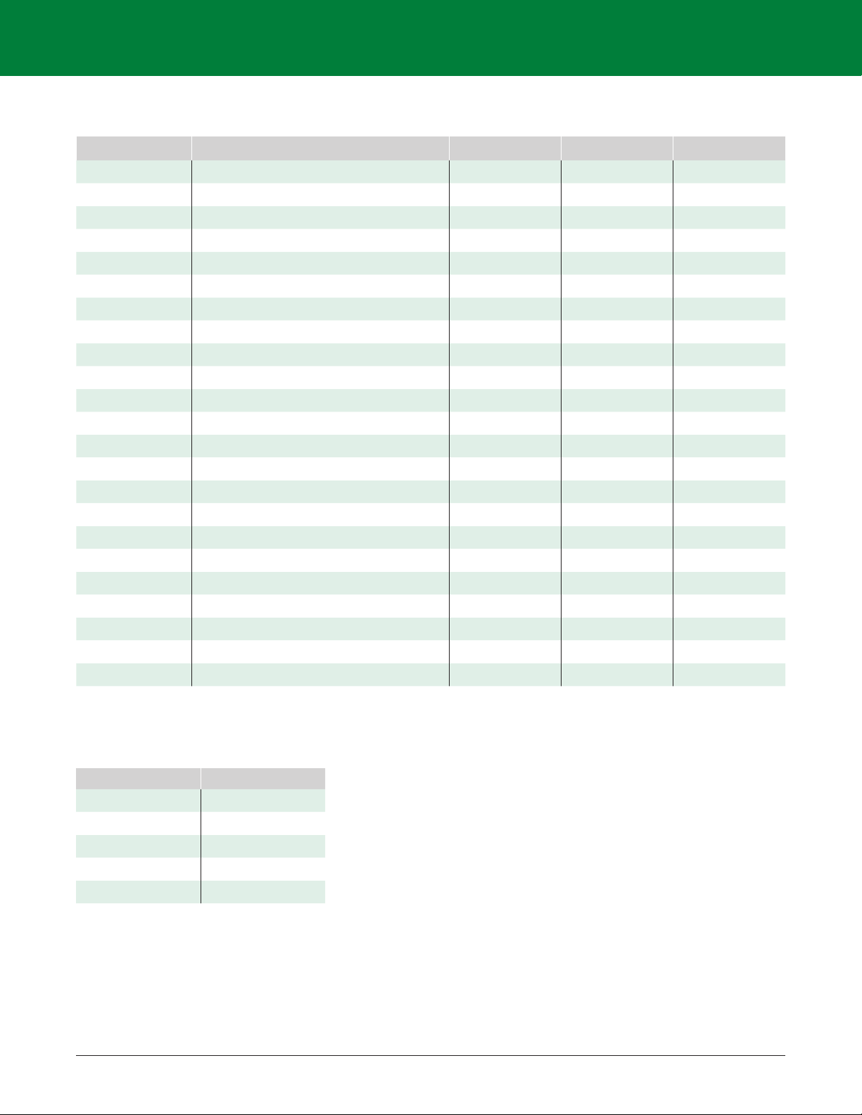
Table 1 - MP8000 Memory Map Settings (Configuration parameters)
FIELD
NAME
MODBUS REGISTER
ADDRES
HEX
ADDRESS
DECIMAL
SIZE
DEFAULT DESCRIPTION FORMAT PERMISSION
CONFIGURATION REGISTERS
FW_REV 0x0000 0 2 0x03000000 Software Revision C R
PC 0x0002 2 1 0x8002 Product Code B R
MULT 0x0003 3 1 1 Current Transformer Ratio B R/W
PT 0x0004 4 1 1 Potential Transformer Ratio B R/W
LV 0x0005 5 2 600.00 Low Voltage Holdoff Condition H R/W
HV 0x0007 7 2 0.00 High Voltage Holdoff Condition H R/W
VUB 0x0009 9 1 5 Voltage Unbalance Holdoff Percentage G R/W
TC 0x000A 10 1 5 NEMA Trip Class B R/W
OC 0x000B 11 2 10.00 Overcurrent Threshold (FLA of motor) H R/W
UC 0x000D 13 2 5.00 Undercurrent Threshold H R/W
UCTD 0x000F 15 1 5 Undercurrent Trip Delay L R/W
CUB 0x0010 16 1 7 Current Unbalance Threshold G R/W
CUBTD 0x0011 17 1 30 Current Unbalance Trip Delay Q R/W
LIN 0x0012 18 1 0 Linear Overcurrent Trip Delay L R/W
RD0 0x0013 19 2 0 Restart Delay 0 L R/W
RD1 0x0015 21 2 0 Restart Delay 1 L R/W
RD2 0x0017 23 2 300 Restart Delay 2 L R/W
RD3 0x0019 25 2 300 Restart Delay 3 L R/W
RU 0x001B 27 1 1 Restart Attempts for Undercurrent Trips B R/W
RF 0x001C 28 1 1 Restart Attempts for all other faults B R/W
GF 0x001D 29 2 0 Ground Fault Current Threshold H R/W
GFTD 0x001F 31 1 50 Ground Fault Trip Delay S R/W
GFID 0x0020 32 1 0 Ground Fault Inhibit Delay L R/W
LKW 0x0021 33 2 0.00 Low Power Trip Threshold H R/W
HKW 0x0023 35 2 0.00 High Power Trip Threshold H R/W
HPRTD 0x0025 37 1 60 High Power Trip Delay C R/W
STLP 0x0026 38 1 0 Stall Percentage (of OC) B R/W
STLTD 0x0027 39 1 5 Stall Trip Delay Q R/W
STLID 0x0028 40 1 0 Stall Inhibit Delay Q R/W
MACCTRL 0x0029 41 1 0 Motor Acceleration Control Bits C R/W
MACTD 0x002A 42 1 0 Motor Acceleration Trip Delay Q R/W
ENDIS 0x002B 43 2 0 Feature Enable/Disable Mask C R/W
CNFG 0x002D 45 2 0x6001 Hardware Configuration Fields C R/W
COMCFG 0x002F 47 2 0x00000000 Communication Configuration C R/W
CAN_CNFG 0x0031 49 2 0x00000000 CAN Configuration C R/W
MOD_CNFG 0x0033 51 2 0x00000000 ModBus Configuration C R/W
NAME 0x0035 53 6 “” Friendly Device Name R R/W
CMD 0x003B 59 1 N/A Command Interface C W
* See Instruction Manual (IM) Ref section for more details
See Instruction Manual (IM) tables 4.2 & 4.5 for default values
NOTE: “Reserved” fields should be maintained as 0.
4
Page 7

MP8000 Programming Guide
© 2018 Littelfuse Protection Relays & Controls
Table 2 - CNFG Details (Hardware Configuration Control Register)
FIELD NAME BIT MASK DESCRIPTION
CNFG bit Masks
GFMT 0 0x0001
AUXCNTL 1 0x0002 AUX Relay Control
Disable BLE Module 2 0x0004 If bit set BLE module will be disabled
Reserved 3 0x0008
Reserved 4 0x0010
Single-Phase Motor 5 0x0020 Single phase motor operation
3-Phase w/1 Volt 6 0x0040 3phase motor with single voltage PT
Reserved 7 0x0080
Reserved 8 0x0100
PTC Enable 9 0x0200
Reserved 10 0x0400
Reserved 11 0x0800
CBA Phase Rotation 12 0x1000 Phase rotation
RD0 on Power Up 13 0x2000 RD0 on power up
RD1 on Current Loss 14 0x4000 RD1 on Current Loss
Reserved 15 0x8000
Ground fault motor trip selection, if set release motor on GF, is not set energize the
alarm relay
*Available in the listed Version or newer.
5
Page 8

MP8000 Programming Guide
© 2018 Littelfuse Protection Relays & Controls
Table 3 - Memory Map Data Format Codes
All fields are in little endian
CODE DESCRIPTION SIZE BYTES
A uint8_t 1
B uint16_t 2
C uint32_t 4
D int8_t 1
E int16_t 2
F int32_t 4
G uint16_t Base 10.xx 2
H uint32_t Base 10.xx 4
I int16_t Base 10.xx 2
J int32_t Base 10.xx 4
K uint32_t Unix time_t 4
L uint32_t Seconds 4
M int32_t Seconds 4
N int16_t Signed Percentage 2
O uint8_t Base 10.x 1
P int16_t Power Factor 2
Q uint16_t Seconds 2
R String N/A
S uint16_t 1/10s of a Seconds (10 == 1 sec) 2
Command Register
Write to the Command Interface register (0x0076) to perform the following tasks.
Table 4 – CMD (Command Interface; address 0x0076)
Value Defined Name Description
0x0009
0x0010
0x0011
0x 0012
0x0013 CMD_RESET_MOTOR_RUN_TIME
0x0014
0x0020
0x0030
0x0031 CMD_AUX_RELAY_ON Energize/Activate the AUX relay
0x0040
0x0041 CMD_CLR_BLE_DISABLE_BIT
*Available in the listed Version or newer.
CMD_MOTOR_RESTART Attempt to Restart the Motor
CMD_RESET_MOTOR_SERVICE_TIME Reset Motor Service time to NOW
CMD_FAULT_LOOKUP Fault Lookup (From FIDX and FRO) [Modbus only]
CMD_RESET_FACTOR_DEFAULTS Reset Configuration to Factory Defaults
Reset the amount of time current has been detected flowing though
the MP8000
CMD_RESET_MOTOR_SCNT Reset the number of times the motor has started
CMD_FORCE_TRIP Force the MP8000 to trip, require restart to recover
CMD_AUX_RELAY_OFF De-Energize/Release the AUX relay
CMD_SET_BLE_DISABLE_BIT Set the BLE Disable bit of the CNFG register (bit 2) and stop BLE operation
Clear the BLE Disable bit of the CNFG register (bit 2) and allow
BLE operation
6
Page 9

MP8000 Programming Guide
© 2018 Littelfuse Protection Relays & Controls
Real Time Status
All parameters listed in Table 5 - MP8000 Memory Map Real Time Status are updated every second.
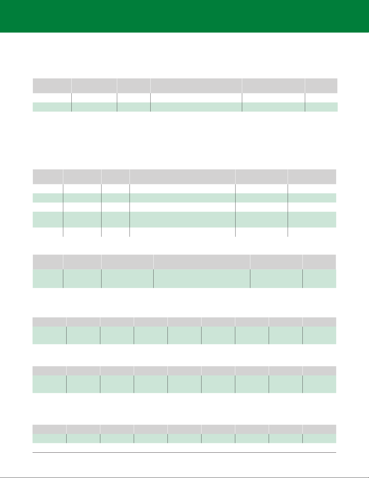
Table 5 - MP8000 Memory Map Real Time Status
MODBUS REGISTER
FIELD NAME
ADDRESS
HEX
ADDRESS
DECIMAL
SIZE
REALTIME STATUS REGISTERS
DESCRIPTION FORMAT PERMISSION
MST 0x0200 512 2
Time since motor last serviced
(can only be written to zero)
L R
MRT 0x0202 514 2 Time since motor started L R
SCNT 0x0204 516 1
Start Count -- Number of Motor starts (since last
cleared)
B R
FAULT_STAT 0x0205 517 2 Current Fault Status Mask C R
WARN_STAT 0x0207 519 2 Current Warning Status Mask C R
FAULT_CODE 0x0209 521 1 Indicates the reason we have tripped or are in holdoff B R
RTDT 0x020A 522 2 Remaining Trip Delay Time L R
RDR 0x020C 524 2 Restart Time Remaining L R
TCU 0x020E 526 1 Thermal Capacity Used B R
MLF 0x020F 527 1 Measured Line Frequency G R
SEQ 0x0210 528 1 Measured Phase Sequence B R
VUBM 0x0211 529 1 Measured Voltage Unbalance G R
CUBM 0x0212 530 1 Measured Current Unbalance G R
V1 0x0213 531 2 Measured line 1 Voltage RMS H R
V2 0x0215 533 2 Measured line 2 Voltage RMS H R
V3 0x0217 535 2 Measured line 3 Voltage RMS H R
I1 0x0219 537 2 Measured line 1 Current RMS H R
I2
0x021B 539 2 Measured line 2 Current RMS H R
I3 0x021D 541 2 Measured line 3 Current RMS H R
P1 0x021F 543 2 Measured line 1 Power C R
P2 0x0221 545 2 Measured line 2 Power C R
P3 0x0223 547 2 Measured line 3 Power C R
PF1 0x0225 549 1 Measured line 1 Power Factor P R
PF2 0x0226 550 1 Measured line 2 Power Factor P R
PF3 0x0227 551 1 Measured line 3 Power Factor P R
IGF 0x0228 552 2 Ground Fault Current H R
PTC 0x022A 554 1 Positive Temperature Coeficent E R
MOTORR 0x022B 555 1 Motor Relay State (0-open, 1-energized) E R
AUXR 0x022C 556 1 Aux Relay State (0-open, 1-energized) E R
*Available in the listed Version or newer.
7
Page 10

MP8000 Programming Guide
© 2018 Littelfuse Protection Relays & Controls
Fault Record Retrieval
There are two methods of requesting a fault record: By index, and by date. (See Table 6)
To request fault records by Index:
1. Write the fault index to the FRI register (0x300). Note, this index is zero based, so the most recent fault
record will have an index of zero.
a. Also the maximum valid index is 1023
2. Write to the CMD register (0x0076) with command 0x11 (see Table 4)
3. Continuously read the FRI register until it has been updated to 0xFFFF
4. The fault record is ready to read, starting at address 0x0308. (see Table 6)
To request fault records by date:
1. Write zero to the FRI register (0x0300).
2. Write the UNIX (32bit) time stamp to the FRO register (0x0304).
a. The log entry with the next earlier time entry will be retrieved.
3. Write to the CMD register (0x0076) with command 0x11 (see Table 4)
4. Continuously read the FRI register until it has been updated to 0xFFFF
5. The fault record is ready to read, starting at address 0x0308. (see Table 6)
Table 6 - Fault Record Retrieval
FIELD
NAME
FRI 0x0300 768 2 Fault Request Index (Or base DT) C W
FRO 0x0302 770 2 Fault Request Offset F W
FCODE 0x0304 772 2 Fault Code indicating the source of the fault B R
FDT 0x0306 774 2 Date Time of Fault K R
V1F 0x0308 776 2 Measured line 1 Voltage RMS H R
V2F 0x030A 58 2 Measured line 2 Voltage RMS H R
V3F 0x030C 780 2 Measured line 3 Voltage RMS H R
I1F 0x030E 782 2 Measured line 1 Current RMS H R
I2F 0x0310 784 2 Measured line 2 Current RMS H R
I3F 0x0312 786 2 Measured line 3 Current RMS H R
MRTF 0x0314 788 2 Time since motor started H R
TCUF 0x0316 790 2 Thermal Capacity Used L R
P1F 0x0318 792 2 Measured line 1 Power C R
P2F 0x031A 794 2 Measured line 2 Power C R
P3F 0x031C 796 2 Measured line 3 Power C R
PF1F 0x031E 798 1 Measured line 1 Power Factor P R
PF2F 0x031F 799 1 Measured line 2 Power Factor P R
PF3F 0x0320 800 1 Measured line 3 Power Factor
IGFF 0x0321 801 2 Ground Fault Current H R
VUBF 0x0323 803 1 Measured Voltage Unbalance G R
CUBF 0x0324 804 1 Measured Current Unbalance G R
FAF 0x0325 805 1 Frequency Measured from Phase A G R
SEQF 0x0326 806 1 Measured Phase Sequence G R
FSDF 0x0327 807 5 Fault Specific Data N.A R
ADDRESS HEX
MODBUS REGISTER
ADDRESS
DECIMAL
SIZE
DESCRIPTION FORMAT PERMISSION
P R
8
Page 11
MP8000 Programming Guide
© 2018 Littelfuse Protection Relays & Controls
Table 7 - Fault Status
ALIAS ACTIVE FAULT/TRIP CONDITION MASK FAULT CODE *VERSION
NOFAULT No fault or warning condition 0x00000000 0 2.0.17.12
OCF Tripped on overcurrent 0x00000001 1 2.0.17.12
UCF Tripped on undercurrent 0x00000002 2 2.0.17.12
CUBF Tripped on current unbalance 0x00000004 3 2.0.17.12
CSPF Tripped on current single-phasing 0x00000008 4 2.0.17.12
CTCF Tripped on contactor failure 0x00000010 5 2.0.17.12
GFF Tripped on ground fault 0x00000020 6 2.0.17.12
HPF Tripped on High Power Fault 0x00000040 7 2.0.17.12
LPF Tripped on low power fault 0x00000080 8 2.0.17.12
LCVF Low Control Voltage Fault 0x00000100 9 2.0.17.12
PTCF Trip or holdoff due to PTC fault 0x00000200 10 2.0.17.12
RMTF Tripped triggered from remote source 0x00000400 11 2.0.17.12
LIN Tripped on Linear Overcurrent 0x00000800 12 2.0.17.12
STALL Tripped Motor Stall 0x00001000 13 2.0.17.12
ARD0 Active Restart Delay Field Bit 0 0x00010000 N/A 2.0.17.12
ARD1 Active Restart Delay Field Bit 1 0x00020000 N/A 2.0.17.12
ARD2 Active Restart Delay Field Bit 2 0x00040000 N/A 2.0.17.12
PTCS Tripped on PTC Short 0x00200000 14 2.0.17.12
PTCO Tripped on PTC Open 0x00400000 15 2.0.17.12
MANR Manual Restart Required 0x00080000 N/A 2.0.17.12
FWUpdate F/W Update n/a 0x1000 2.0.17.12
UNDEFF Undefined trip condition 0x00100000 61166 2.0.17.12
FMEA MP8000 Replacement Fault 0x01000000 4097 2.2.17.15
*Available in the listed Version or newer.
Table 8 - Active Restart Delay
ARD[2:0] RDR IS
000 Inactive
001 RD0
010 RD1
011 RD2
100 RD3
9
Page 12

MP8000 Programming Guide
© 2018 Littelfuse Protection Relays & Controls
Table 9 - Warning Status
ALIAS ACTIVE WARNING OR HOLDOFF MASK WARN CODE
NOWARN No Warning Condition Present 0x00000000 N/A
W_OCF Overcurrent Detected 0x00000001 N/A
W_UCF Undercurrent Detected 0x00000002 N/A
W_CUBF Current Unbalance Detected 0x00000004 N/A
W_CSPF Current Single Phasing Detected 0x00000008 N/A
W_CTCF Contactor Failure Detected 0x00000010 N/A
W_GFF Ground Fault Detected 0x00000020 N/A
W_HPF High Power Detected 0x00000040 N/A
W_LPF Low Power Detected 0x00000080
W_LCVF Low Control Voltage Detected 0x00000100 N/A
W_PTCF PTC Holdoff 0x00000200 N/A
W_LIN Linear Overcurrent Detected 0x00000800 N/A
W_STALL Motor Stall Detected 0x00001000 N/A
LVH Low Voltage Holdoff 0x00010000 100
HVH High Voltage Holdoff 0x00020000 101
VUBH Voltage Unbalanced Holdoff 0x00040000 102
PHSQ Phase Sequence Holdoff 0x00080000 103
UNDEFF Undefined Holdoff 0x00100000 N/A
GFALARM Ground Fault Alarm 0x00800000 16
N/A
MP8000 ETHERNET/IP INTERFACE
MP8000 Network Settings
By default, the MP8000 is configured to request its IP address and network configuration from a DHCP server. It
is also possible to set a static IP address using the MP8000 software or Littelfuse smartphone/tablet app.
RSLOGIX5000 Setup
Add a Generic EtherNet/IP Module as a New Module to the PLC. The Comm Format for the MP8000 is
DATA-SINT. The Input Assembly is instance 50 or 51 with a size of 1, and the Output Assembly is instance 2
with a size of 1.
LED Indication
There are two LED’s on the RJ45 connector on the side of the MP8000. The amber LED indicates the existence
of a network connection. The green LED indicates data transfer.
ETHERNET/IP OBJECTS
Identify Object
The module supports the following objects:
Table 10 - Ethernet NET/IP Objects
CLASS DESCRIPTION
0x01 Identity
0x04 Assembly
10
Form: PF777
Rev: 1-A-051817
Page 13
MP8000 Programming Guide
© 2018 Littelfuse Protection Relays & Controls
Identity Object Class Services
Get_Attribute_Single: Returns contents of specified attribute.
Table 11 - Identity Class 1, Instance 0 Attributes
ATTRIBUTE
NUMBER
ATTRIBUTE
NAME
SERVICES DESCRIPTION
DEFAULT, MINIMUM,
MAXIMUM
1 Revision Get Revision of this object 1 UINT
2 Max Instance Get Maximum number of instances 1 UINT
Identity Object Instance Services
Get_Attribute_Single: Returns contents of specific attribute.
Set_Attribute_Single: Modify the specified attribute.
Reset: Performs reset services based on the parameter.
Table 12 - Identity Class 1, Instance 1 Attributes
ATTRIBUTE
NUMBER
ATTRIBUTE
NAME
SERVICES DESCRIPTION
1 Vendor ID Get Identification of each vendor by number 691 UINT
2 Device Type Get Motor Overload 03 UINT
3 Product Code Get Motor protection relay series 8000 UINT
4 Revision Get
Major revision must match the eds value
(Major.Minor)
7 Product Name Get Human readable identification MP8000 SHORT_STRING
Assembly Object
DEFAULT, MINIMUM,
MAXIMUM
3, 002 UINT
DATA
TYPE
DATA
TYPE
ATTRIBUTE
NUMBER
1
0x01
ATTRIBUTE
NAME
SERVICES DESCRIPTION
Revision Get_Attibute_Single Revision of this object. 1, 1, 1 UINT
DEFAULT, MINIMUM,
MAXIMUM
Input Assembly
Table 13 - Assembly Class (4), Instance (50), Attribute (3) – Input 1 (1 Byte): Basic Overload
BYTE BIT7 BIT6 BIT5 BIT4 BIT3 BIT2 BIT1
0 Reserved Reserved Reserved Reserved Reserved Reserved Reserved
Table 14 - Assembly Class (4), Instance (51), Attribute (3) – Input 1 (1 Byte): Extended Overload
BYTE BIT7 BIT6 BIT5 BIT4 BIT3 BIT2 BIT1
0 Reserved Reserved Reserved Reserved Reserved Reserved Warning
Output Assembly
Table 15 - Assembly Class (4), Instance (2), Attribute (3) – Output 1 (1 Byte)
BYTE BIT7 BIT6 BIT5 BIT4 BIT3 BIT2 BIT1
0 Reserved Reserved Reserved Reserved Reserved Fault Reset Reserved Reserved
DATA
TYPE
BIT0
Faulted/
Trip
BIT0
Faulted/
Trip
BIT0
11
Page 14

MP8000 Programming Guide
© 2018 Littelfuse Protection Relays & Controls
Table 16 -Configuration Object
ATTRIBUTE
ID
1 MULT Current Transformer Ratio R/W UINT 1
2 PT Potential Transformer Ratio R/W UINT 1
3 LV Low Voltage Holdoff Condition R/W UDINT 600
4 HV High Voltage Holdoff Condition R/W UDINT 0
5 VUB Voltage Unbalance Holdoff Percentage R/W UINT 5
6 TC NEMA Trip Class R/W UINT 5
7 OC Overcurrent Threshold (FLA of motor) R/W UDINT 10
8 UC Undercurrent Threshold R/W UDINT 5
9 UCTD Undercurrent Trip Delay R/W UINT 5
10 CUB Current Unbalance Threshold R/W UINT 7
11 CUBTD Current Unbalance Trip Delay R/W UINT 30
12 LIN Linear Overcurrent Trip Delay R/W UINT 0
13 RD0 Restart Delay 0 R/W UDINT 0
14 RD1 Restart Delay 1 R/W UDINT 0
15 RD2 Restart Delay 2 R/W UDINT 300
16 RD3 Restart Delay 3 R/W UDINT 300
17 RU Restart Attempts for Undercurrent Trips R/W UINT 1
18 RF Restart Attempts for all other faults R/W UINT 1
19 GF Ground Fault Current Threshold R/W UDINT 0
20 GFTD Ground Fault Trip Delay R/W UINT 50
21 GFID Ground Fault Inhibit Delay R/W UINT 0
22
23 HKW High Power Trip Threshold R/W UDINT 0
24 HPRTD High Power Trip Delay R/W UINT 60
25 STLP Stall Percentage (of OC) R/W UINT 0
26 STLTD Stall Trip Delay R/W UINT 5
27 STLID Stall Inhibit Delay R/W UINT 0
28 MACCTRL Motor Acceleration Control Bits R/W UINT 0
29 MACTD Motor Acceleration Trip Delay R/W UINT 0
30 ENDIS Feature Enable/Disable Mask R/W UDINT 0
31 CNFG Hardware Configuration Fields R/W UDINT 0x6001
32 COMCFG Communication Configuration R/W UDINT 0x00000000
33 CAN_CNFG CAN Configuration R/W UDINT 0x00000000
34 MOD_CNFG ModBus Configuration R/W UDINT 0x00000000
35 NAME Friendly Device Name R/W STRING “”
36 CMD Command Interface R/W UINT N/A
NAME DESCRIPTION ACCESS TYPE DEFAULT
LKW Low Power Trip Threshold R/W UDINT 0
12
Page 15

MP8000 Programming Guide
© 2018 Littelfuse Protection Relays & Controls
Table 17 - Real-Time Object
ATTRIBUTE
ID
1 MULT Time since motor last serviced (can only be written to zero) R UDINT
2 MRT Time since motor started R UDINT
3 SCNT Start Count -- Number of Motor starts (since last cleared) R UINT
4 FAULT_STAT Current Fault Status Mask R UDINT
5 WARN_STAT Current Warning Status Mask R UDINT
6 FAULT_CODE Indicates the reason we have tripped or are in holdoff R UINT
7 RTDT Remaining Trip Delay Time R UDINT
8 RDR Restart time remaining R UDINT
9 TCU Thermal Capacity Used R UINT
10 MLF Measured Line Frequency R UINT
11 SEQ Measured Phase Sequence R UINT
12 VUBM Measured Voltage Unbalance R UINT
13 CUBM Measured Current Unbalance R UINT
14 V1 Measured line 1 Voltage RMS R UDINT
15 V2 Measured line 2 Voltage RMS R UDINT
16 V3 Measured line 3 Voltage RMS R UDINT
17 I1 Measured line 1 Current RMS R UDINT
18 I2 Measured line 2 Current RMS R UDINT
19 I3 Measured line 3 Current RMS R UDINT
20 P1 Measured line 1 Power R UDINT
21 P2 Measured line 2 Power R UDINT
22 P3 Measured line 3 Power R UDINT
23 PF1 Measured line 1 Power Factor R UINT
24 PF2 Measured line 2 Power Factor R UINT
25 PF3 Measured line 3 Power Factor R UINT
26 IGF Ground Fault Current
27 PTC Positive Temperature Coeficent R UINT
28 MOTORR Motor Relay State (0-open, 1-energized) R UINT
29 AUXR Aux Relay State (0-open, 1-energized) R UINT
NAME DESCRIPTION ACCESS TYPE
R UDINT
Table 18 - Control Supervisor Object
ATTRIBUTE ID NAME ACCESS TYPE
10 Faulted R BOOL
11 Warning R BOOL
12 FaultRst W BOOL
13
Page 16

MP8000 Programming Guide
© 2018 Littelfuse Protection Relays & Controls
SPECIFI C AT IONS
Protocol EtherNet/IP
Ports 1
IP Address 1
Number of Connections 1
Connection:
Connector RJ45
Cable CAT5
Length 100 m (328’)
Interface 10BASE-T, 100 BASE-Tx
14
 Loading...