

Page 1
INSTALLATION INSTRUCTIONS
FOR SYMCOM’S LOAD SENSOR
MODEL LSRU-AL
BE SURE POWER IS DISCONNECTED PRIOR TO INSALLATION!
FOLLOW NATIONAL, STATE, AND LOCAL CODES!
READ THESE INSTRUCTIONS ENTIRELY BEFORE INSTALLATION!
The Model LSRU-AL is a dual trip point load monitor. It can be used to
determine feed rates, tool wear, loss of prime on pumps, mixer viscosity, and
all types of over and under load conditions. When the current draw is within
the limits dened by the two user adjustments, the relay is energized. When
the current falls outside of this range for one second, the relay will
de-energize.
INSTALLATION
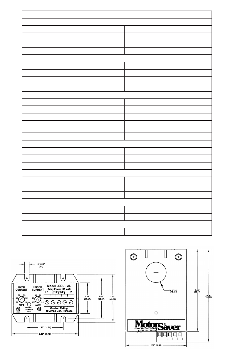
1. Mount the Model LSRU-AL near one of the conductors of the load being
monitored. If the unit will be used in a dusty or wet environment, an
appropriate NEMA rated enclosure should be used.
2. Insert one of the conductors of the load through the sensor hole in the
LSRU-AL.
a) For currents greater than 1 amp, proceed to step #3.
b) For currents less than 1 amp, the conductor must be looped. Refer
to the table below to determine the number of conductors needed
through the sensor window.
NOTE: The OC and/or UC trip points must be set based on ‘I
eff
’ for
current range 1 units.
ACTUAL CURRENT NUMBER OF CONDUCTORS EFFECTIVE CURRENT (I
0.5 - 1.0 3 1.5 - 3.0
0.25 - 0.5 5 1.25 - 2.5
For values less than 0.25 consult the factory.
)
eff
3. Turn the user adjustments to the desired settings.
4. Wire the appropriate control voltage to L1 and L2.
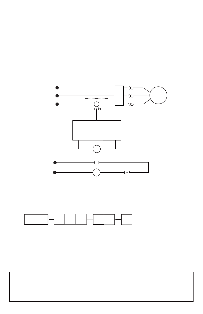
5. Connect the output relay to the control circuitry. The proper wiring scheme
may vary depending on the required action when a fault occurs. (A wiring
diagram is shown in Figure 1 that utilizes the NO contact.)
2880 North Plaza Drive, Rapid City, SD 57702 • (800) 843-8848
Page 2
LSRU
Unit Description
Model # Voltage Range Options Current Range
024 - 18 to 30 VAC
115 - 90 to 135 VAC
1 - 0 to 5 Amps
2 - 5 to 25 Amps
3 - 25 to 100 Amps
A L
OL
OL
OL
OL
MAGNETIC
CONTACTOR
L1
L2
L3
MOTOR
LOGIC INPUT
PLC OR OTHER
AUTOMATED
CONTROL SYSTEM
LOGIC OUTPUT
CONTROL
VOLTAGE
3 PHASE
POWER
LSRU-AL
RL1
M
RL1
6. Energize the load to be monitored. Verify normal running amps have been
achieved. The LED will be lit under normal operating conditions (the current
sensed is at an acceptable level) indicating the output contacts are energized
(NO is closed and NC is open).
NOTE: The LSRU-AL is a fail-safe design, meaning the NO (normally
open contact) will be open if the LSRU fails or control power is
interrupted.
7. The installation is now complete.
FIGURE 1: TYPICAL WIRING DIAGRAM
Any questions or comments call SymCom at 1-800-843-8848 or
SymCom warrants its microcontroller based products against defects in material or workmanship
for a period of ve (5) years from the date of manufacture. All other products manufactured by
SymCom shall be warranted against defects in material and workmanship for a period of two (2)
years from the date of manufacture. For complete information on warranty, liability, terms, and
conditions, please refer to the SymCom Terms and Conditions of Sale document.
08/09/03 -2-
1-605-348-5580
Page 3
MODEL LSRU-AL SPECIFICATIONS
CONTROL VOLTAGE
LSRU-024-xx-x 18 - 30 VAC
LSRU-115-xx-x 90 - 135 VAC
FREQUENCY 50 to 60 Hz
POWER 2 Watts (Maximum)
CURRENT RANGE
LSRU-xxx-AL-1 0 - 5 Amps
LSRU-xxx-AL-1.5 0 - 10 Amps
LSRU-xxx-AL-2 5 - 25 Amps
LSRU-xxx-AL-3 25 - 100 Amps
ADJUSTMENTS
Overcurrent (can not be set below UC) Adjustable through entire current range
Undercurrent (can not be set above OC) Adjustable through entire current range
FIXED TRIP DELAY 1 Second
FIXED RESTART DELAY
MOTOR ACCELERATION TIME 2 Seconds
REPEATABILITY
Current ±2%
Timing ±10%
ISOLATION 600 VAC
OUTPUT CONTACT RATING - SPDT
Pilot Duty Rating 480 VA @ 240 VAC
General Purpose Rating 10 A @ 240 VAC
OPERATING TEMPERATURE -400 to +700 C
TERMINALS
Wire AWG #12 - #24
Maximum Torque 7 inch-pounds
STANDARDS PASSED
CSA and CSA-NRTL/C LR 46510-35
Unit will energize the contacts as soon as
the current level is within limits
-3- 08/09/03
Page 4

Visit our website at www.symcominc.com for our
complete catalog and new product listings!
2880 North Plaza Drive, Rapid City, SD 57702
Phone: (800) 843-8848 or (605) 348-5580
FAX: (605) 348-5685
 Loading...