

Page 1
INSTALLATION
INSTRUCTIONS
Rapid City, SD, USA, 05/2009
MODEL ISS-105-ISO-3
MODEL ISS-105-ISO-4
MODEL ISS-105-ISO
Revision B1
II_ISS-105-ISO-B1
2880 North Plaza Drive, Rapid City, South Dakota 57702
(800) 843-8848 · (605) 348-5580 · fax (605) 348-5685
Page 2
TO PREVENT IGNITION OF FLAMMABLE OR COMBUSTIBLE ATMOSPHERES,
DISCONNECT POWER FROM SYSTEM PRIOR TO INSTALLATION OR SERVICE!
READ THESE INSTRUCTIONS ENTIRELY BEFORE INSTALLATION.
CAUTION: Only personnel trained in intrinsically safe systems should install this
equipment. Improper installation may result in serious injury or damage. Before
proceeding with installation, read and understand these instructions completely. The
ISS-105-ISO Isolated Switch is UL913 listed as an associated apparatus for
interfacing between hazardous and non-hazardous areas. The ISS-105-ISO must be
installed in a non-hazardous area. Follow SymCom's Control Drawing ISS-105 on the
last page of this bulletin for proper installation. All wiring connected to a hazardous
location must be separated from all non-intrinsically safe wiring. Description of special
wiring methods can be found in the National Electrical Code ANSI/NFPA 70, Article
504 Intrinsically Safe Systems. Check your state and local codes for additional
requirements.
INSTALLATION:
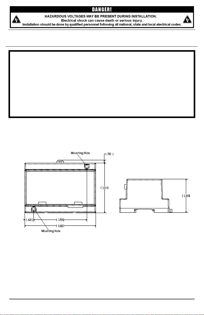
1. Mount the ISS-105-ISO in a non-hazardous location on a DIN-rail, or by installing two
#6-#8 screws into the mounting holes shown in Figure 1.
2. Connect wiring per SymCom's Control Drawing ISS-105. Follow all hazardous code
requirements when installing wiring to the input terminals.
Figure 1: Mounting Diagram
OPERATION:
The ISS-105-ISO relays are 120VAC powered isolated switches suitable for transferring
switch states from hazardous locations to non-hazardous locations. Each input controls
the corresponding output. The green LEDs illuminate when the corresponding input is
closed. The red LEDs illuminate when the corresponding relay is energized.
© 2009 SymCom, Inc. All Rights Reserved 2
Page 3

CHANNEL INVERT:
The inversion adjustment allows all channels to have either positive or negative logic.
Channels cannot be inverted independently.
Positive Logic: Relay closes when input closes.
Invert adjustment is fully counter clockwise.
Negative Logic: Relay opens when the input closes.
Invert adjustment is fully clockwise.
ISS-105-ISO-3 & ISS-105-ISO-4:
Inputs and Outputs 3 and 4 are not present on the ISS-105-ISO-3.
Input and Output 4 is not present on the ISS-105-ISO-4.
SPECIFICATIONS
Control Voltage
Frequency
Maximum Input Power
Operating Temperature
Storage Temperature
Relative Humidity
Terminals
Wire AWG 12-20 AWG
Torque 6 in.-lbs.
Relay Contacts
Pilot Duty B300 or 480VA @ 240VAC
General Purpose
Entity Parameters
Voc=16.8 V
Isc=1.2 mA
La=100mH
Ca=0.39uF
Po= Voc * Isc
Provides Intrinsically Safe Circuits in
the Following Locations:
Class I, Div 1 & 2, Groups A, B, C, D
Class II, Div 1 & 2, Groups E, F, G
Class III
Standards Passed
Safety UL 913 6th Edition
Electrostatic Discharge (ESD) IEC 61000-4-2, Level 3, 6 kV contact, 8 kV air
Radio Frequency Immunity (RFI) 10V/m @ 150 MHz
Fast Transients IEC 61000-4-4, Level 3, 4 kV input power
2 kV inputs/outputs
Class of Protection IP20 (finger-safe)
Mechanical Dimensions 3.703” W x 5.025” L x 2.350” D
For warranty information, please see Terms and Conditions at
www.symcom.com
108-132VAC
50/60 Hz
4 W
-20 to 55°C (-4 to 131°F)
-40 to 80°C (-40 to 176°F)
Up to 95% non-condensing
7A @ 240VAC
4
© 2009 SymCom, Inc. All Rights Reserved 3
 Loading...