

Page 1
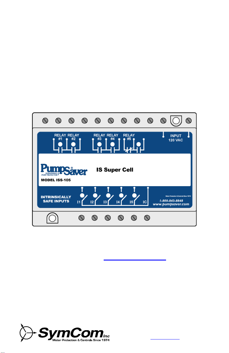
PumpSaver® ISS-105
IS Super Cell
Installation Guide
Visit our website at www.symcom.com for our
complete catalog and new product listings!
2880 North Plaza Drive, Rapid City, South Dakota 57702
(800) 843-8848 · (605) 348-5580· fax (605) 348-5685
www.symcom.com
Page 2

Introduction .................................................................................... .. 3
warranted aga
two (2) years from the date of manufacture. For complete information on
warranty, liability, terms, returns, and cancellations, please refer to the
Quick Start.....................................................................................4
Model Description..........................................................................5
Time Delay....................................................................................5
Mode Selector ...............................................................................5
Option Selector..............................................................................6
1. Pumping Modes............................................................................ 6
Duplex...........................................................................................6
Triplex: High/Low Alarm.................................................................6
Quadplex.......................................................................................6
Separate Pump Stop (SPS)............................................................7
2. IS Supe r Cel l Funct ions...............................................................7
High Alarm.....................................................................................7
Low Alarm.....................................................................................7
Out-of-Sequence Alarm..................................................................7
Audible Alarm................................................................................8
Audible Alarm Logic/Fail-Safe.........................................................8
Clearing Alarms.............................................................................8
Alternation.....................................................................................8
Alternation On................................................................................9
Alternation On, Non-Alternating Pump Enabled............................... 9
Alternation Off................................................................................9
Disabling Pumps............................................................................9
External Inputs............................................................................. 10
· External Silence / Alarm Rese t...............................................10
· Externa l Power Rese t ............................................................ 10
· Ex terna l Alternation Conf igura tion.......................................... 10
3. Wiring Diagrams........................................................................10
4. 5-Channe l Relay Mode............................................................... 21
Positive/Negative Logic................................................................21
Latched Output............................................................................ 21
Time Delay Output.......................................................................22
· Delay-On-Make.....................................................................22
· Delay-On-Break..................................................................... 22
Model ISS-105 Specifications.........................................................23
SymCom warrants its microcontroller-based products against defects in
material or workmanship for a period of five (5) years from the date of
manufacture. All other products manufactured by SymCom shall be
inst defects in material and workmanship for a period of
SymCom Terms and Conditions of Sale document.
2
12/04
Page 3

Introduction
The PumpSaver® ISS-105 IS Super Cell is a smart, fivechannel, intrinsicall y safe relay and pump controller. It has a
long list of features that are needed for multiple pump
applications. The IS Super Cell can indicate low, high and outof-sequence alarms. It can do alternating pump control, nonalternating pump control, or alternating control with one nonalternating pump. The non-alternating pump can be used as
either a jockey or emergency pump and can optionally start the
non-alternati ng pump after every 50 cycles of the lead pump, to
keep it working freely. Using the built-in DIP switches, individual
pumps can be disabled when taken out of service for repair or
maintenance.
The IS Super Cell has the following features and capabilities:
4High, Low and Out-Of-Sequence Alarms
4Variable Time Delay/Lag Pump Delay
4Separate Pump Stop
4Pump Alternation w/ or w/o Non-Alternating Pump
4Jockey or Emergency Pump
4Duplex, Triplex or Quadplex Pump Modes
4Pump Up or Pump Down Functions
4External Silence, Reset and Alternation Configuration
4Five-Channel Relay
3
12/04
Page 4
Quick Start
The IS Super Cell can operate as an intrinsically safe pump control for
eight different pumping configurations. Duplex, Triplex, Quadplex and
Duplex SPS (Separate Pump Stop) pumping modes are possible for
either Pump Up or Pump Down applications. Refer to page 21 for the
full description of five-channel relay operation.
Read 1. Pumping Modes, page 6, for details of the features and mode
descriptions of the unit.
1. If the desired pump configuration is known, follow Table 1 to the
page showing the typical wi ring diagram and setup for each
mode.
2. If further description is needed in choosing which mode to use, see
Table 2 and Table 3 to view the capabilities of each pumpin g mode
and look at the typical wi ring diagrams of the eight different
pumping modes starting on page 11.
3. Once the desired configuration is determined, punch out and
slide the correct card i nto the slot on the front of the IS Super Cell
to display the input and output connections.
Mode Selector
Switch
Position
0 5-Channel Relay – Mode 0 22
1 Duplex Pump Down – Mode 1 11
2 Triplex Pump Down – Mode 2 12
3 Quadplex Pump Down – Mode 3 13
4 Duplex SPS Pump Down – Mode 4 14
5 Duplex Pump Up – Mode 5 15
6 Triplex Pump Up – Mode 6 16
7 Quadplex Pump Up – Mode 7 17
8 Duplex SPS Pump Up – Mode 8 18
Table 1. Mode Selector
Mode Description Page
4
12/04
Page 5
Model Description
WARNING!
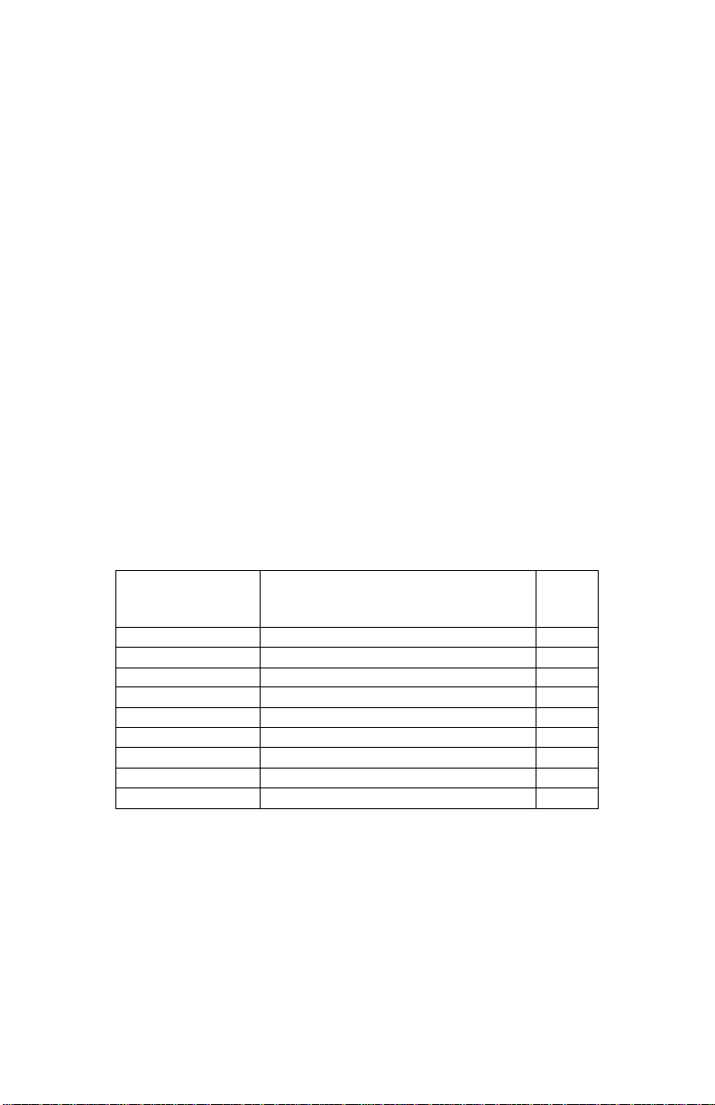
The ISS-105 has three adjustable controls to set the mod e of operation:
1. Mode Selector
2. Option Selector
3. Time Delay
To ensure proper initialization and operation,
set the m ode and option selectors before applying
power to the unit.
Time Delay
The Time Delay can be set from 2–255 seconds and is the Lag Pump
delay in each of th e pumping modes. When the Lead Float
opens/closes, the Time Delay starts and once i t expires, the Lag Pump
is ready to turn on. After the Lag Pump turns on, any necessary pumps
will turn on suc cessively after a two-second time delay each.
Mode Selector
This dial is used to select the operation mode. A description of each
mode is shown i n Table 1. The capabilities of each pumping mode and
the Non-Alternating Pump designations are shown in Table 2 below.
Duplex Triplex Quadplex Duplex SPS
# Pumps 2 3 4 2
High Alarm Yes *Yes No **Yes
Low Alarm Yes *Yes No **Yes
Out-of-Sequence Alarm Yes Yes Yes Yes
# Stop Floats 1 1 1 2
Pump Di rection Up/Down Up/Down Up/Down Up/Down
Non-Alternating Start Float Lag 1 Lag 2 Lag 3 N/A
Non-Alternation Pump Pump 2 Pump 3 Pump 4 N/A
Alternator Yes Yes Yes Yes
Table 2. Mode Capabilities
* On a Triplex pump system, either a High or Low Alarm is available, but not both.
See Triplex Mode descriptio n for more details.
** On a Duplex SPS system, a High Alarm is typical on a Pump Down application
and a Low Alarm is typical on a Pump Up.
5
12/04
Page 6

Option Selector
Table 2 describes th e Option Selector for all pumping modes.
(· Indicates the function is available for the pum p mode)
Option
Selector
Position
1 High Alarm
2 Low Alarm
3 Pump 1
4 Pump 2
5 Pump 3
6 Pump 4
7
8
9
10
Function Description Duplex Triplex Quadplex
Audible Alarm Relay
State/Fail Safe
Alternator Select 0,
(ALS-0, see Tabl e 4)
Alternator Select 1,
(ALS-1, see Tabl e 4)
Alternator Select 2,
(ALS-2, see Tabl e 4)
* On a Triplex pump system, either a High or Low Alarm is available, but not both.
See Triplex Mode descriptio n for more details.
1. Pumping Modes
Duplex
In a Duplex mode, two pumps are used with one Stop Float and High
and Low Alarms.
Triplex: High/Low Alarm
In a Triplex mode, three pumps are used with one Stop Float.
In a Triplex Pump Down mode, a High Alarm is the typical
configuration with the Option Selector switches 1=ON (High Alarm) and
2=OFF (Low Alarm).
If a Low Alarm is desired, the al arm float must be moved to the position
in the tank below the Stop Float and Option Selector switches must be
1=OFF and 2=ON.
In a Triplex Pump Up mode, a Low Al arm is the ty pical configuration
with the Option Sel ector switches 1=OFF (Hi gh Alarm) and 2=ON (Low
Alarm).
If a High Al arm is desired, the alarm float must be m oved to the position
in the tank above the Stop Float and Option Selector switches must be
1=ON and 2=OFF
Quadplex
In a Quadplex m ode, four pumps are used with one Stop Float and no
alarms floats.
Duplex SPS
(Separate
Pump Stop)
· *· ·
· *· ·
· · · ·
· · · ·
· ·
·
· · · ·
· · · ·
· · · ·
· · · ·
Table 3. Opti on Selector
6
12/04
Page 7

Separate Pump Stop (SPS)
In the Duplex SPS mode, both the Lead and Lag pumps have their own
stop floats.
In an SPS Pump Down mode, a High Al arm is th e typical configuration with
Option Selector switches 1=ON (High Alarm) and 2=OFF (Low Alarm).
If a Low Alarm is desired, the alarm float must be moved to the positi on
in the tank below the Lead Stop Float, and Option Selector switches
must be 1=OFF, and 2=ON.
In an SPS Pump Up mode, a Low Alarm is the typical configuration with
Option Selector switc hes 1=OFF (High Alarm) and 2=ON (Low Alarm).
If a High Alarm is desired, the alarm float must be moved to the
position in the ta nk above the Lead Stop Float, and Option Sel ector
switches must be 1=ON and 2=OFF.
2. IS Super Cell Functions
High Alarm
The High Alarm is activated when the High Alarm Float closes,
indicating the pumps are unable to keep the water level down on a
Pump Down applic ation. If the High Al arm Float closes at any time, all
pumps will turn on, bypassing th e 10-second out-of-sequence trip delay,
and the adjus table Time Delay.
If a High Alarm is used on a Pump Up application, the alarm will be
activated when the High Alarm Float cl oses indicating the water level
has been pumped too high, possibly due to a defective Stop Float, and
will turn off all pumps.
During a High or Low Alarm, the Alarm LED and Audible Alarm LED will
be on. If the High or Low Alarm condition ends, the Audible Alarm will
turn off and the Alarm LED will flas h indicating the alarm had occu rred,
but is not present now. If the High or Low Alarm occurs again, the
Audible Alarm LED will turn on again, but t he Alarm LED will rem ain
flashing.
The unit must be silenced or reset to clear the flashing al arm LEDs.
Low Alarm
The Low Alarm is activated when the Low Alarm Float opens indicating
the pumps are unable to keep the water level up on a Pump Up
application. If the Pump Up Low Alarm Float opens at any time, except
if a High Al arm is activated, all pumps will turn on.
If a Low A larm is used on a Pump Down application, the alarm will be
activated when the Low Alarm Float opens indicati ng the water level has
been pumped too low. This may be a result of a defective stop float.
The Low Alarm will not turn off the pumps though, but will activate the
low alarm relay; another form of pump-dry protection such as the
SymCom Model 777 may be required.
Out-of-Sequence Alarm
When a float i n the series does not open or close in sequence, the
Audible Alarm will be activated and input LED(s) will flash until t he unit
7
12/04
Page 8

is reset or power is cycled. An out-of- sequence condition has to exist for
10 seconds before th e ISS-105 will alarm. W hen the stop float fai l s open
in pump down mo de or closed in pump up mode, an Out-of- Sequence
Alarm will NOT occur and pumps will not turn on with floats. In this case,
all pumps will turn on when the High/Low Alarm is activated. Thus, in
Quadplex mode, pumps will never turn on if th e Stop Float ma lfuncti ons.
Audible Alarm
The Audible Alarm is activated when a High, Low or Out-of Sequence
Alarm occurs. The Audible Al arm will turn off when there is no longer
high or low alarms or if the unit is silenced.
Audible Alarm Logic/Fail-Safe
The Audible Alarm rela y can be configured to operate in either a FailSafe mode (p osition 7=ON), or a Non Fail-Saf e mode (position 7=OFF).
In Fail-Safe mode, the NC (Normally Closed) contacts will beopen
during normal operation and closed during an alarm. In Non Fail-Safe
mode, the NC contacts will be cl osed during normal operation and open
during an alarm.
Clearing Alarms
The external Silence / Alarm Reset button will clear t he Audible Alarm.
The Reset button or cycling power will clear Out-of-Sequence Alarms.
Alternation
The ISS-105 i s equipped with a built-in alternator that determines which
pump will st art each pum ping cycle. This alt ernator is configured using
switches ALS-0, ALS-1 and ALS-2 of the Option Selector.
Function
ALS-0
Position 8
Alternation On ON ON ON
Alternation On OFF ON ON
Alternation On, Non-
Alternating Pump Enabled (1)
Alternation On, Non-
Alternating Pump Enabled (1)
Alternation Off, Force Pum p 1
as Lead
Alternation Off, Force Pum p 2
as Lead
Alternation Off, Force Pum p 3
as Lead (2)
Alternation Off, Force Pum p 4
as Lead (3)
*ON OFF OFF
**OFF OFF OFF
OFF ON OFF
OFF OFF ON
ON ON OFF
ON OFF ON
Table 4. Alternator Options
Note (1) In Duplex Mode, this setting is the same as Alternation On.
Note (2) In Duplex Mode, this will force Pump 1 as lead and will cycl e Pump 2 every 50
Note (3) In Duplex Mode, this will force Pump 2 as lead and will cycle Pump 1 ever y 50
cycles of the lead pump
cycles of the lead pump
* If ALS-0 is ON in this mode, the Non-Alternating Pump will cycle when the NonAlternating Float changes state, or after 50 cycles of the Lead Float.
** If ALS-0 is OFF the Non-Alternating Pump will cycle only when the Non-Alternating
Float changes state.
8
ALS-1
Position 9
ALS-2
Position 10
12/04
Page 9

Alternation On
When the alternator is on, each pump will be alternated as the
Lead Pump (see Table 5).
Cycle 1 Cycle 2 Cycle 3 Cycle 4 Cycle 5
Pump 1 Lead Lag 3 Lag 2 Lag 1 Lead
Pump 2 Lag 1 Lead Lag 3 Lag 2 Lag 1
Pump 3 Lag 2 Lag 1 Lead Lag 3 Lag 2
Pump 4 Lag 3 Lag 2 Lag 1 Lead Lag 3
Table 5. Pump Sequence
Alternation On, Non-Alternating Pump Enabled
The Triplex and Quadplex pump modes are equipped with an
optional Non-Alternating Pump. This pump will not be included in
the normal pump alternation sequence when ALS-1 and ALS-2
(positions 9 and 10) are both OFF. If ALS-0 (position 8) is ON, th e
Non-Alternating Pump will cycle when the Non-Alternati ng Float
changes state or after every 50 cycles of th e Lead Float. If ALS-0
is OFF, the Non-Alternating Pump will only cycle if the NonAlternating Float chang es state.
The last pump i n the float sequence (highest #) is the NonAlternating Pump and can be used as either a jockey or emergency
pump. (See Tabl e 2, page 5 for Non-Alternating Pump and Float
details for each pumpi ng mode.)
A Jockey Pump is typically a smaller pump that will always be
used first in the pump sequence. In order to implement a
jockey pump; the Non-Alt ernating Pump Float must be moved
in the tank to just above the Stop Float in a Pump Down
system, and to just below the Stop Float in a Pump Up system.
See Figure 9 (page 19), an exam ple wiring diagram using a
Jockey Pump in a Duplex Pump Down system.
An Emer gency Pump is usually a larger pump that is always
used last. In order to implement an emergency pump; the
Non-Alternating Pump is already the last pump in the
sequence so there i s no need to mo ve the float. See Figur e 10
(page 20), an example wiring diagram using an Emergency
Pump in a Duplex Pump Down system.
Alternation Off
When the alternator is off, a Lead Pump can be forced by setting ALS-0,
1 & 2 (s ee Table 4). The remaining pumps will start in a sequential
order as each float opens/closes.
Disabling Pumps
Using the built-in DIP switc hes, individual pumps can be disabled, when
taken out of service for repair or maintenance.
9
12/04
Page 10

External Inputs
A five-pin connector is provided for optional external inputs.
· External Silence / Alarm Reset
This input allows for an external NO (Normally Open) pushbutton
that will silence audib le alarms and clear flashing alarm lights.
· External Power Reset
This input allows for an external NO pushbutton to reset the IS
Super Cell, causing th e same effect as a power cycle.
· External Alternation Configuration
For Duplex Mode, a SPDT (Single Pole Double Throw) switch can
be connected to close RTCL1 or RTCL2 (remote controls) to force
Pump 1 or 2 as the Lead Pump. Opti on Selector Positions 8, 9 &
10 must be OFF. If th e switch is i n the middle position, pumps will
be in alternation mode.
For Triplex and Q uadplex Modes t wo SPST (Single Pole Single
Throw) switches can be connected to force Pump 1,2,3 or 4 to be
the Lead Pump. Option Selector Positions 9 & 10 must be OFF.
To force Pump 1 or 2 as Lead, Positi on 8 must be OFF.
To force Pump 3 or 4 as Lead, Positi on 8 must be ON.
For alternation mode, close bot h RTCL1 and RTCL2.
3. Wiring Diagrams
The following Figures 1-10, show ty pical wiring diagrams for all pumping
modes available for th e IS Super Cell.
10
12/04
Page 11

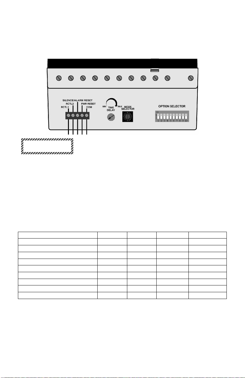
Figure 1. Typical Wiring for Duplex Pump Down - Mode 1
Switch State
Mode Selector Switch 1
Time Delay Adjustment MIN
Option Selector Switch
1 High Alarm ON
2 Low Alarm ON
3 Pump 1 ON
4 Pump 2 ON
5 Pump 3 NA
6 Pump 4 NA
7 Fail-Safe OFF
8 ALS-0 ON
9 ALS-1 ON
10 ALS-2 ON
Table 6. Typical Duplex Pump Down Setup
11
12/04
Page 12

Figure 2. Typical Wiring for Triplex Pump Down - Mode 2
Switch State
Mode Selector Switch 2
Time Delay Adjustment MIN
Option Selector Switch
1 High Alarm ON
2 Low Alarm OFF
3 Pump 1 ON
4 Pump 2 ON
5 Pump 3 ON
6 Pump 4 NA
7 Fail-Safe OFF
8 ALS-0 ON
9 ALS-1 ON
10 ALS-2 ON
Table 7. Typical Triplex Pump Down Setup
12
12/04
Page 13
Figure 3. Typical Wiring for Quadplex Pump Down - Mode 3
Switch State
Mode Selector Switch 3
Time Delay Adjustment MIN
Option Selector Switch
1 Hi gh Alarm NA
2 Low Alarm NA
3 Pum p 1 ON
4 Pum p 2 ON
5 Pum p 3 ON
6 Pum p 4 ON
7 Fail-Safe OFF
8 ALS-0 ON
9 ALS-1 ON
10 ALS-2 ON
Table 8. Typic al Quadplex Pump Down Setup
13
12/04
Page 14
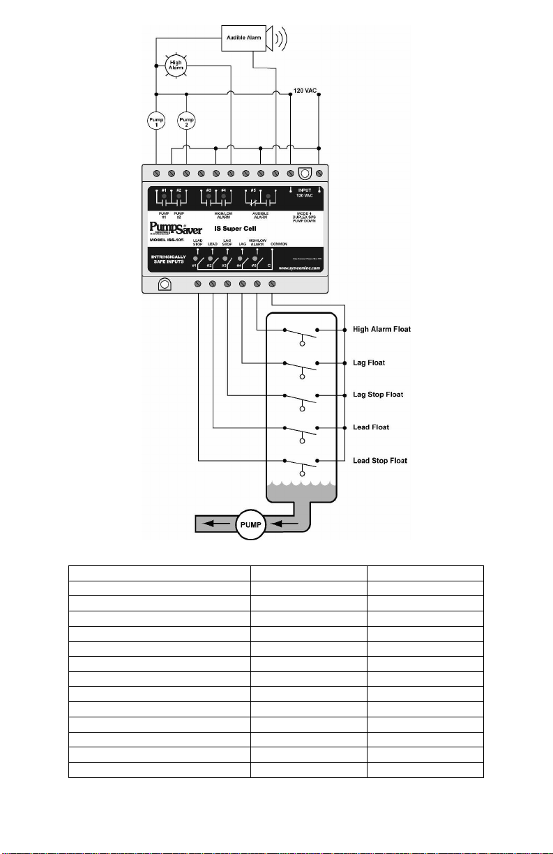
Figure 4. Typical Wiring for Duplex SPS Pum p Down - Mode 4
Switch State
Mode Selector Switch 4
Time Delay Adjustment MIN
Option Selector Switch
1 High Alarm ON
2 Low Alarm OFF
3 Pump 1 ON
4 Pump 2 ON
5 Pump 3 NA
6 Pump 4 NA
7 Fail-Safe OFF
8 ALS-0 ON
9 ALS-1 ON
10 ALS-2 ON
Table 9. Typi cal Duplex SPS Pump Down Setup
14
12/04
Page 15

Figure 5. Typical Wiring for Duplex Pump Up - Mode 5
Switch State
Mode Selector Switch 5
Time Delay Adjustment MIN
Option Selector Switch
1 Hi gh Alarm ON
2 Low Alarm ON
3 Pump 1 ON
4 Pump 2 ON
5 Pump 3 NA
6 Pump 4 NA
7 Fail-Safe OFF
8 ALS-0 ON
9 ALS-1 ON
10 ALS-2 ON
Table 10. Typic al Duplex Pump Up Setup
15
12/04
Page 16

Figure 6. Typical Wiring for Triplex Pump Up - Mode 6
Switch State
Mode Selector Switch 6
Time Delay Adjustment MIN
Option Selector Switch
1 Hi gh Alarm OFF
2 Low Alarm ON
3 Pum p 1 ON
4 Pum p 2 ON
5 Pum p 3 ON
6 Pum p 4 NA
7 Fail-Safe OFF
8 ALS-0 ON
9 ALS-1 ON
10 ALS-2 ON
Table 11. Typic al Triplex Pump Up Setup
16
12/04
Page 17
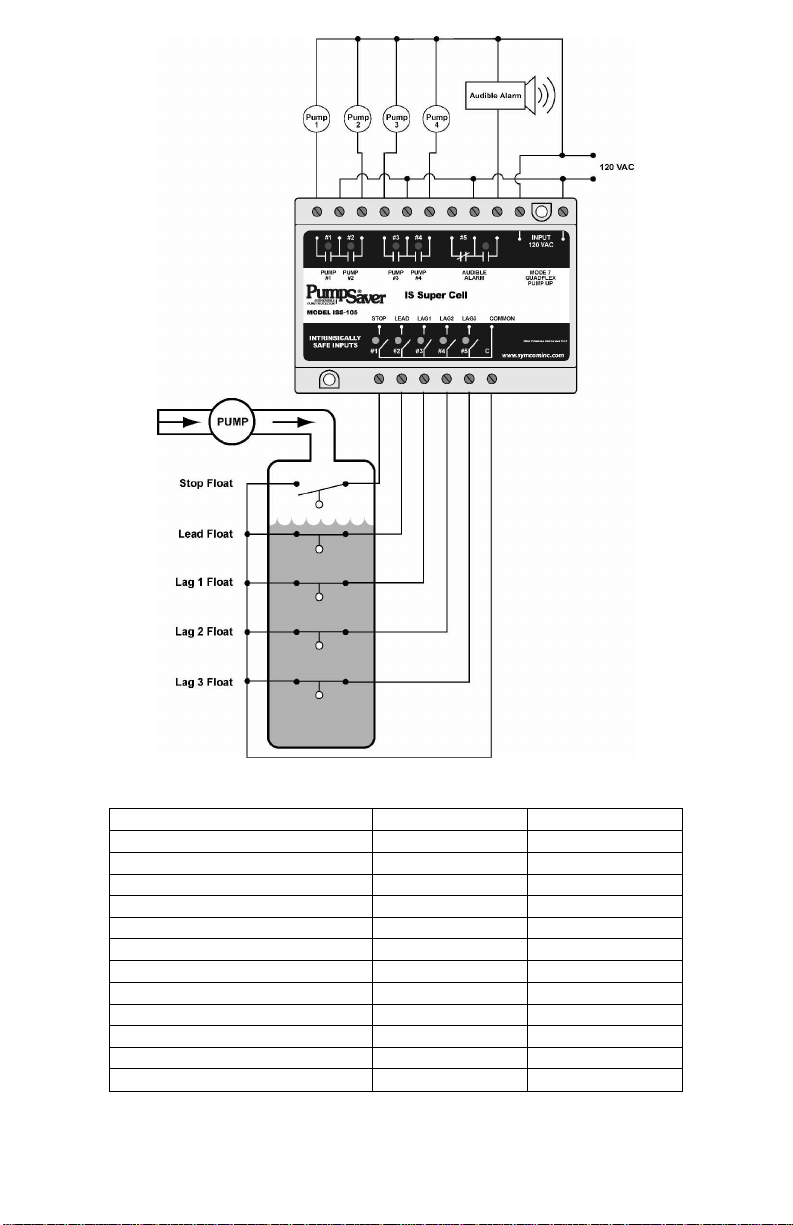
Figure 7. Typical Wiring for Qua dplex Pump Up - Mode 7
Mode Selector Switch 7
Time Delay Adjustment MIN
Option Selector Switch
1 High Alarm NA
2 Low Alarm NA
3 Pump 1 ON
4 Pump 2 ON
5 Pump 3 ON
6 Pump 4 ON
7 Fail-Safe OFF
8 ALS-0 ON
9 ALS-1 ON
10 ALS-2 ON
Table 12. Typic al Quadplex Pump Up Setup
17
12/04
Page 18
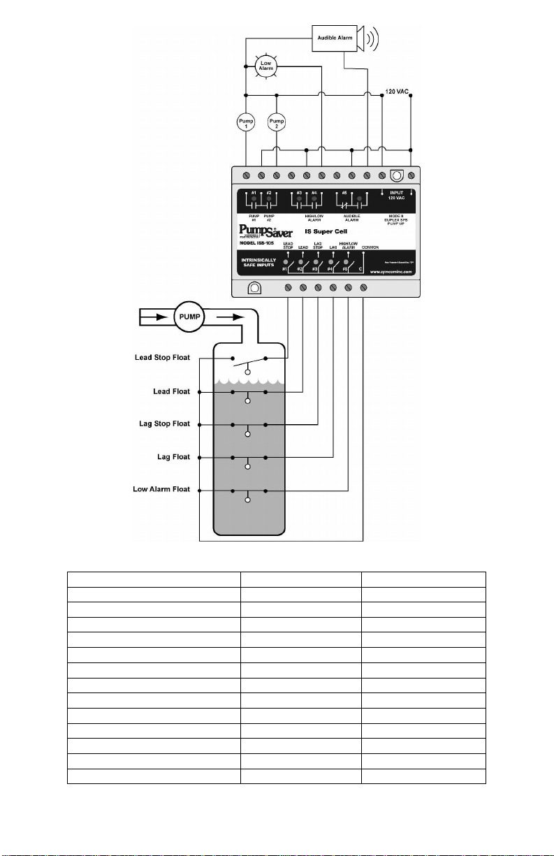
Figure 8. Typical Wiring for Duplex SPS Pum p Up - Mode 8
Switch State
Mode Selector Switch 8
Time Delay Adjustment MIN
Option Selector Switch
1 High Alarm OFF
2 Low Alarm ON
3 Pump 1 ON
4 Pump 2 ON
5 Pump 3 NA
6 Pump 4 NA
7 Fail- Safe OFF
8 ALS-0 ON
9 ALS-1 ON
10 ALS-2 ON
Table 13. Typical Duplex SPS Pum p Up Setup
18
12/04
Page 19

Figure 9. Typical Wiring for Duplex Pump Down with a Jockey
Pump - Mode 1
Switch State
Mode Selector Switch 1
Time Delay Adjustment MIN
Option Selector Switch
1 High Alarm ON
2 Low Alarm ON
3 Pump 1 ON
4 Pump 2 ON
5 Pump 3 NA
6 Pump 4 NA
7 Fail- Safe OFF
8 ALS-0 OFF
9 ALS-1 ON
10 ALS-2 OFF
Table 14. Typic al Duplex Pump Down w/ Jockey Setup
19
12/04
Page 20
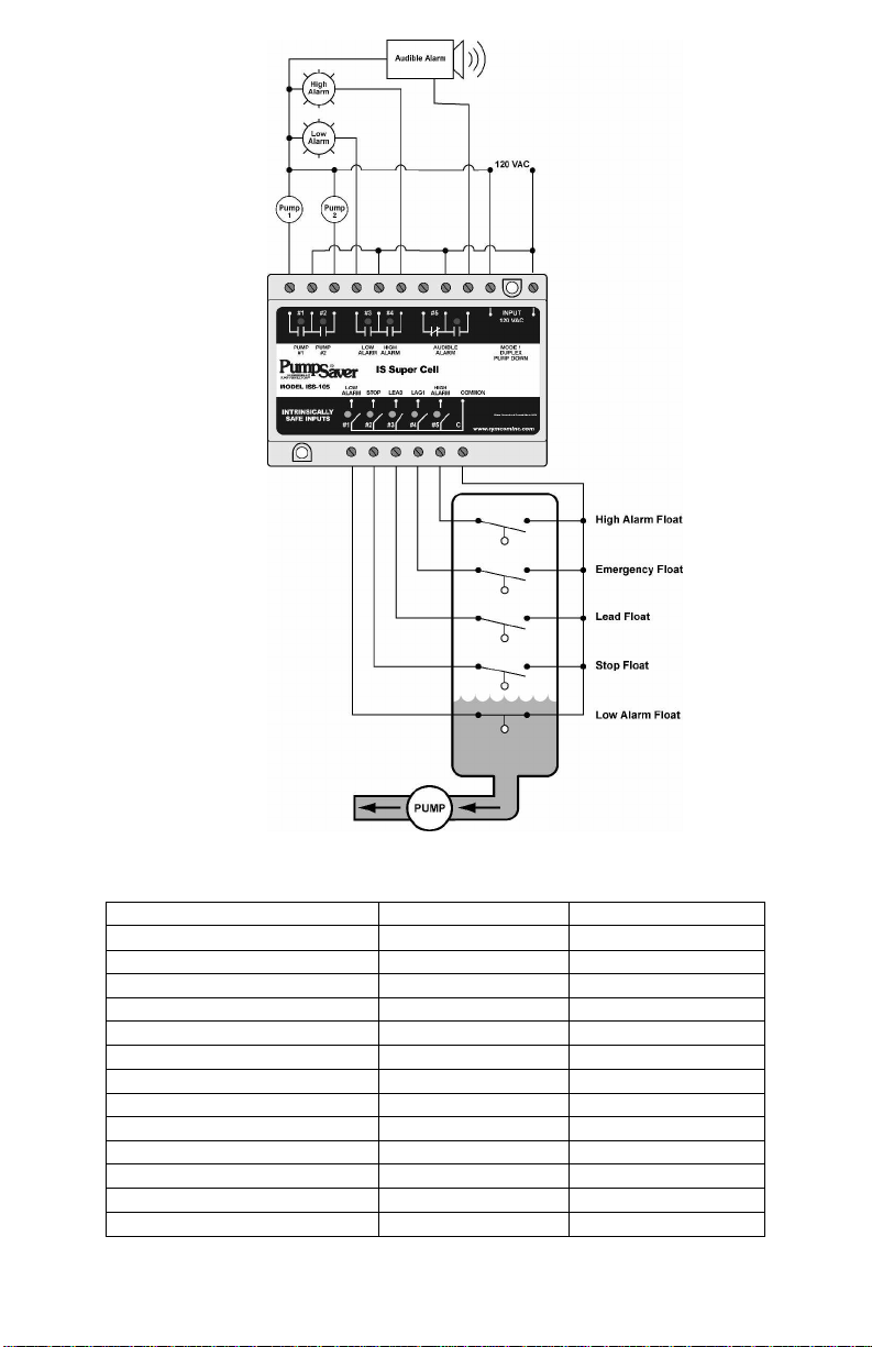
Figure 10. Typical Wiring for Duplex Pump Down with an
Emergency Pump - Mode 1
Switch State
Mode Selector Switch 1
Time Delay Adjustment MIN
Option Selector Switch
1 High Alarm ON
2 Low Alarm ON
3 Pump 1 ON
4 Pump 2 ON
5 Pump 3 NA
6 Pump 4 NA
7 Fail- Safe OFF
8 ALS-0 OFF
9 ALS-1 OFF
10 ALS-2 ON
Table 15. Typic al Duplex Pump Down Setup
20
12/04
Page 21

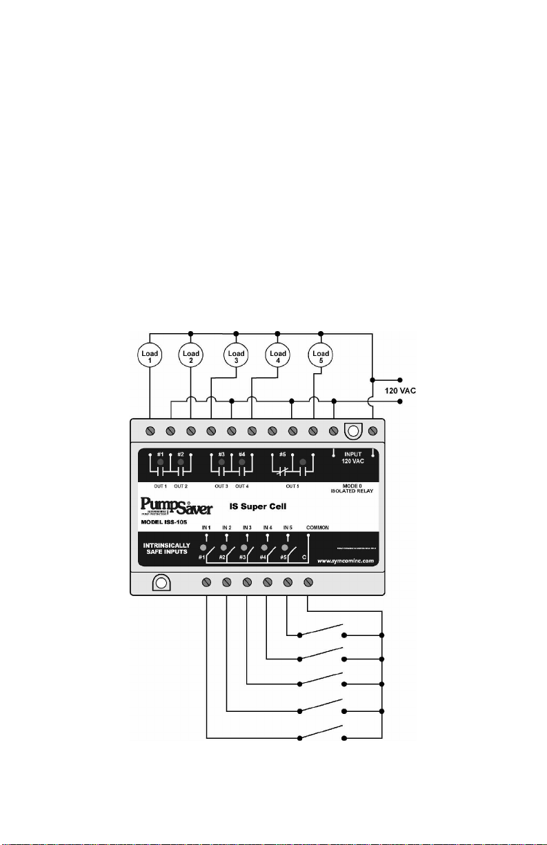
4. Five-Channel Relay Mode
Some unique features of th e Five-Channel Relay mode are descr i bed
below. To use the IS Super Cell in this mode, the Mode Selector
dial must be set to position 0.
Option
Selector
Position
1
2
3 Relay 1 Logic Positive Negative
4 Relay 2 Logic Positive Negative
5 Relay 3 Logic Positive Negative
6 Relay 4 Logic Positive Negative
7 Relay 5 Logic Positive Negative
8
9
10 Not Used ----- -----
Function
Description
Enables Channel 2
Latch
Enables Channel 4
Latch
Selects
Make/Break
Enables Delay-On-
Make/Break Timer
Table 16. Five-Channel Relay Options
ON Function OFF Function
Channel 1 and 2
function normally
Channel 3 and 4
function normally
Delay-On-Break Delay-On-Make
Make/Break Timer
Disabled
Channel 1
Latches Channel 2
Channel 3
Latches Channel 4
Make/Break Timer
Enabled
Positive/Negative Logic
Using positive logic will give the same output as input – if the input is
closed, the corresponding output relay will al so be closed.
If using negative logic, the out put will be the opposite of the input – if
the input is closed, the output relay will be open.
Latched Output
Relays 2 and 4 can be configured as latched relays. Input 2 will cause
relay 2 to close, but this relay will not open until input 1 opens. Relay 4
will close when i nput 4 closes, but will not open until input 3 opens.
21
12/04
Page 22
Time Delay Output
Relay 5 can be confi gured as a Delay-On-Make or a Delay-On-Break
time delay output. All timing starts when the input switch opens or
closes. The time base for this output is adjustable using th e Time Delay
knob and ranges fr om 2-255 seconds.
· Delay-On-Make
If Input 5 closes, the Time Delay will start and LED 5 will flash.
Once the Time Delay has expired, Output Relay 5 will close and the
LED will be on. If Input 5 opens at any point during the timing
cycle, the Time Delay stops and Output Relay 5 remains open.
· Delay-On-Break
If Input 5 opens, the Tim e Delay will start and LED 5 will flash.
Once the Time Delay has expired, Output Relay 5 will open and the
LED will be off. If Input 5 closes at any point during the timing
cycle, the Time Delay stops and Output Relay 5 remains closed.
Figure 11. Typical Wiring for 5-c hannel Relay - M ode 0
22
12/04
Page 23
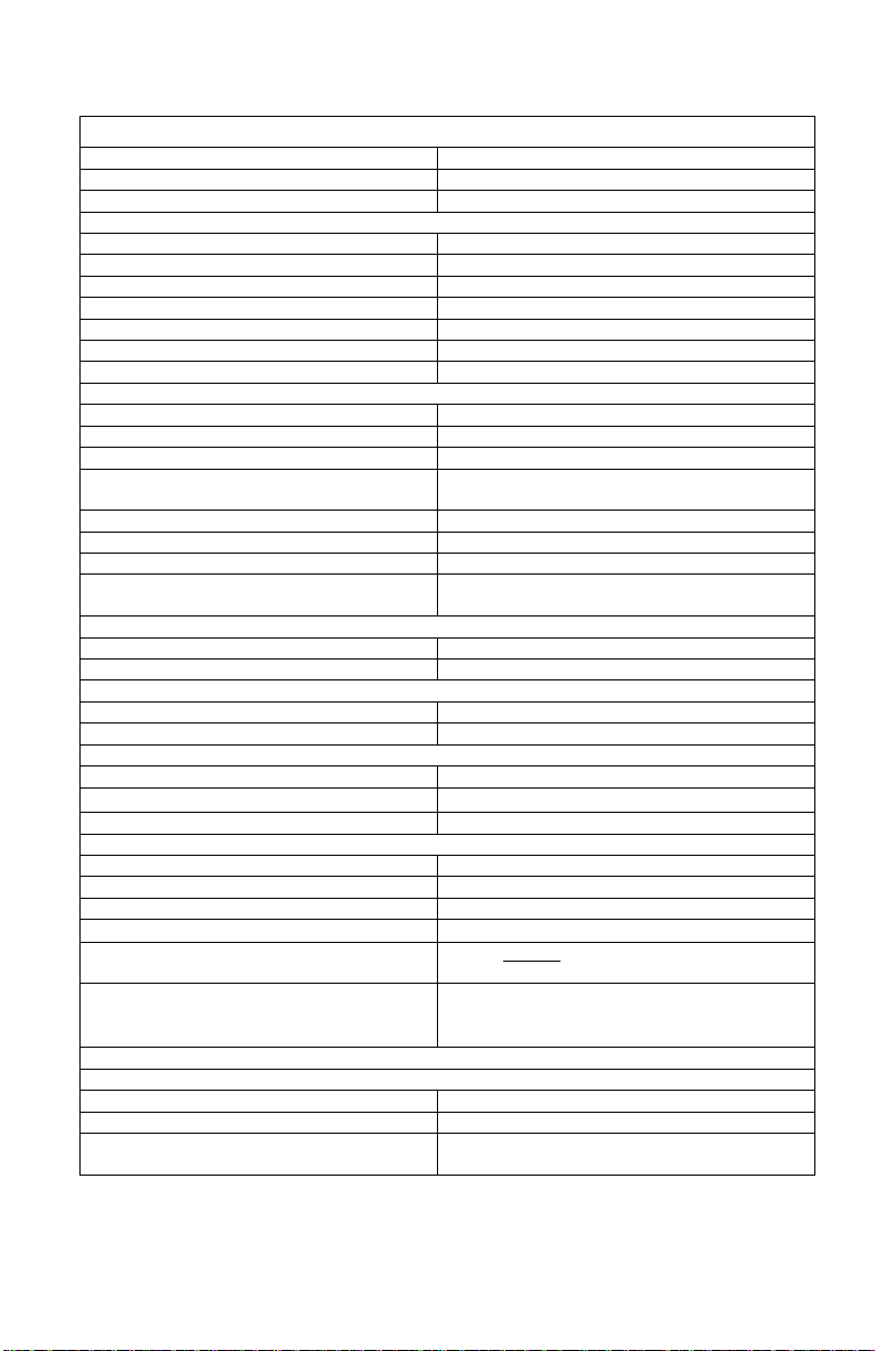
Model ISS-105 Specifications
Control Voltage 108–132VAC
Frequency 50/60 Hz
Power 4 Watts (max.)
Adjustments
Time Delay/Lag Pump Delay 2–255 sec.
Mode Selector 0–8 (9–F: force mode 0)
Opt ion Selector 1–10, ON/OFF
Silence Button dry input only / non IS
Reset Button dry input only / non IS
External Alternation Configuration ALS-1
External Alternation Configuration ALS-2
Pumping Modes A vailable
Duplex Pump Down 2 pumps w/ high and low alarm s
Triplex Pump Down 3 pumps w/ high alar m (typical)
Quadplex Pump Down 4 pumps
Duplex Pump Down SPS
(Sepa rate Pump Stop)
Duplex Pump Up 2 pumps w/ high and low alarms
Triplex Pump Up 3 pump s w/ low alarm (typical)
Quadplex Pump Up 4 pumps
Duplex Pump Up SPS
(Sepa rate Pump Stop)
5-Channel Relay Mode
5-Channel 1 relay latched / time delay output
Operating Temperature -20 to 55°C
Terminals
Wire AWG 12–20 AWG
Torque 6 in.-lbs.
Relay Contacts
Pump Inrush Delay 2 sec.
Entity Parameters
Provides Intrinsically Safe Circuits in
the Following Locations:
Standards Passed
2 pumps w/ high alar m (typical)
2 stop floats
2 pumps w/ low alar m (typical)
2 stop floats
B 300 or 480VA @ 240VAC, Pilot Duty
240 VAC, 7A (max.), General Purpose
Voc=16.8 V
Isc=1.2 mA
La=100mH
Ca=0.39µF
Po = Voc * Isc
4
Class I, Divisions I & II, Groups A, B, C & D;
Class II, Divisions I & II, Groups E, F & G;
and Class III lo cations
Electrostatic Discharge (ESD) IEC 61000-4-2, Level 3, 6 kv contact, 8 kv air
Radio Frequency Immunity (RFI) IEC 61000-4-2, Level 3, 10V/m
Fast Transients
IEC 61000-4-4, Level 3, 4 kv input power
2 kV inputs/outputs
23
12/04
Page 24

ASSOCIATED APPARATUS / APPAREILLAGE CONNEXE
NITION OF FLAMMABLE OR COMBUST ABLE
ATMOSPHERES, DISCONNECT POWER BEFORE SERVICING.
COMPROMETTRE LA SÉCURITÉ INTRINSÈQUE.
See Note 3
pparatus
shall be calculated and must be included in the system calculations as shown in the table above. Cable
capacitance, Ccable, plus intrinsically safe equipment capacitance, Ci, must be less than the marked capacitance,
iated apparatus used. T he same applies for inductance (Lcable, Li a nd La or Lo,
respectively). Where the cable capacitance and inductance per foot are not known, the foll owing values shall be
Load
Load
1
2
RELAY#1RELAY#2REL AY#3RELAY#4RELAY
MODEL ISS-105
I1I2I3I4I5IC
CONTROL DRAWING ISS-105
Non-Hazardous Location
Supply Voltage
120VAC
Load
3
ISSuperCell
Load4Load
#5
5
INPUT
120 VAC
Relay Output Rating
7 Amps @ 240VAC General Purpose
Pilot Duty 480VA @ 2 40VAC, B300
11 5 VAC
Maximum Ambient Temperature Rating
55°C
DEVICE MUST BE INSTALLED IN A SUITABLE ENCLOSURE
WARNING!
TO PREVENT IG
DEVICE MAY ONLY BE REPAIRED BY THE MANUFACTURER
WARNING!
SUBSTITUTION OF COMPONENTS MAY IMPA IR INTRINSIC
SAFETY.
AVERTISSEMENT!
LA SUBSTITUTION DE COMPOSANTS PEUT
See Notes 1 & 2
Capacitance and inductance of the field wiring from the intrinsically safe equipment to the associated a
Ca (or Co), shown on any ass oc
used: Ccable = 60pF/ft., Lcable = 0.2µH/ft.
(800) 843-8848 · (605) 348-5580 · fax (605) 348-5685
www.symcom.com
Class I, Divisions I & II, Groups A, B, C & D;
Class II, Divisions I & II, Groups E, F & G; and
Class III locations
NOTES:
1. Maximum distance between unit and switch contact is
10,000 feet.
2. All non-intrinsically safe wiring shall be separated from
intrinsically safe wiring. Description of special wiring
methods can be found in the National Electrical Code
ANSI/NFPA 70, Article 504 I ntrinsically Safe Systems.
Check your state and local codes for additional
requirements.
3. All switch contacts shall be non-energy storing,
containing no inductance or capacitance.
4. Entity Parameters:
Voc = 16.8V Ca = 0.39µF
Isc = 1.2mA Po = Voc * Isc
La = 100mH 4
5. Entity Parameter Relationships:
IS Equipment
Associated Apparatus
Vmax (or Ui) ≥ Voc or Vt (or Uo)
Imax (or Ii) ≥ Isc or It (or Io)
Pmax, Pi ≥ Po
Ci + Ccable ≤ Ca (or Co)
Li + Lcable ≤ La (or Lo)
2880 North Plaza Drive, Rapid City, South Dakota 57702
Hazardous Location
 Loading...