

INSTALLATION INSTRUCTIONS FOR SYMCOM’S MOTOR SAVER MODEL CP-5
BE SURE POWER IS DISCONNECTED PRIOR TO INSTALLATION!!
FOLLOW NATIONAL, STATE AND LOCAL CODES!
CONNECTIONS
1. Mount the MotorSaver in a convenient location in the pump control panel and near the wires supplying the center pivot
control panel. If the location is wet or dusty, then mount the MotorSaver in a NEMA 3R or 4 enclosure.
2. Run one of the wires supplying the center pivot control panel through the center of the current transformer supplied
with the Model CP-5. DO NOT REMOVE THE CURRENT TRANSFORMER FROM THE MODEL CP-5.
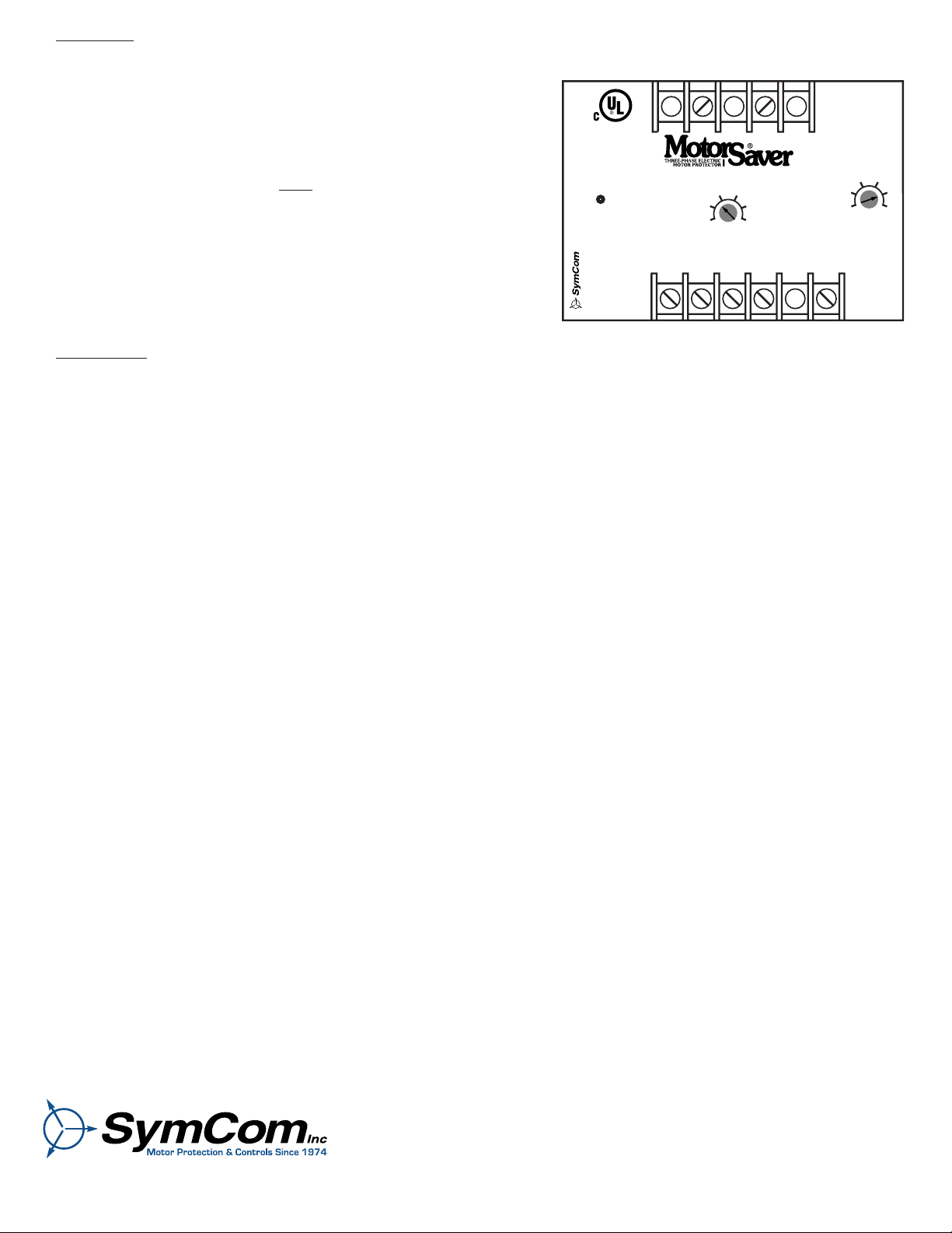
3. Connect the pump control power to the Model CP-5’s internal power terminals marked "L1" and "L2" on the MotorSaver
(See Figure No. 1).
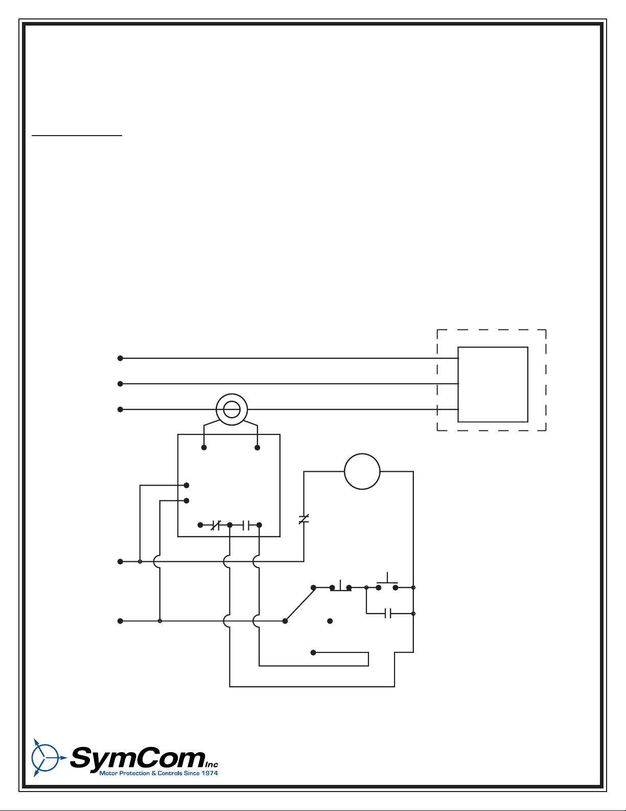
4. Connect the normally open output contact in series with the pump controls as shown in Figure No. 1
FIGURE NO. 1: Typical Wiring Diagram for the Model CP-5.
TYPICAL WIRING DIAGRAM FOR MODEL CP-5
L1
L1
L2
L2
L3
CT1
PUMP
CONTROL
POWER
CT2
MAG.
CENTER
PIVOT
PANEL
COIL
STOP
OFF
M
HAND
AUTO
START
OLs
2880 North Plaza Drive, Rapid City, SD 57702 • (800) 843-8848
SETTINGS
1. Set the trip level by first turning the "TRIP AMPS" pot fully clockwise.
Second, turn on the power to the Model CP-5 ("L1" and "L2"). Third,
turn on the power to the pivot control panel. Be sure the pivot motors
are not running. Fourth, slowly rotate the "TRIP AMPS" pot counterclockwise until the Model CP-5’s output relay energizes (signified by an
audible click and a green color on the LED after a one second delay).
Fifth, turn the "TRIP AMPS" pot back
1/16 of a turn clockwise. This is
the proper set point.
2. Set the "TRIP DELAY" pot to the desired position. The trip delay is
the amount of time after the pivot motors stop running before the pump
is turned off. The Model CP-5 will wait this amount of time before its
output contacts de-energize after setting the "TRIP LEVEL" pot in step
#1 above.
This setting should not normally be lower than 3.5 minutes.
OPERATION
The Model CP-5 will not allow the pump to run until the current feeding the pivot control panel is above the "TRIP AMPS"
setting. After the current to the pivot control panel exceeds the "TRIP AMPS" setting, the output contact will energize, thus
turning on the pump after a 1.0 second reset delay. When the current feeding the pivot control panel drops below the "TRIP
AMPS" setting (signifying shut-down of the pivot motors), the output contact will de-energize, thus turning off the pump after
a trip delay as set on the "TRIP DELAY" dial.
CONGRATULATIONS!!!! YOU HAVE JUST INSTALLED
THE FINEST PIVOT MOTOR CONTROL AVAILABLE!!!
IF YOU HAVE ANY QUESTIONS OR COMMENTS,
PLEASE CONTACT SYMCOM AT
1-800-843-8848
- 2 -
STATUS
OK
GREEN
STATUS
TRIPPED
RED
TRIP DELAY
BLINK RED
TRIP DELAY (MIN)
Pilot Duty Rating
470VA at 600VAC
TRIP AMPS
1
05
4
23
010
28
46
NC C
CT1 CT2
L1 L2
460 VAC
MODEL CP - 5
TOWER MONITOR
Rapid City, SD
IND. CONT. EQ.
LISTED
784X
4/17/03
2880 North Plaza Drive, Rapid City, SD 57702 • (800) 843-8848
 Loading...