

Page 1
BE SURE POWER IS DISCONNECTED PRIOR TO INSTALLATION!
FOLLOW NATIONAL, STATE AND LOCAL CODES.
READ THESE INSTRUCTIONS ENTIRELY BEFORE INSTALLATION.
The CIO-777-PR Module is a convenient and cost-effective Profibus interface capable of providing
discrete control and monitoring of motor starters, drives, and other devices over a Profibus network.
The design of the CIO-777-PR provides the following benefits in both new and existing installations:
reduced field wiring
greater operator efficiency
ease in system startup and commissioning
The CIO-777-PR Profibus module can be DIN rail mounted, or mounted directly to a back panel. The
CIO-777-PR’s compact size, ease of wiring and Profibus communications capability makes the use
of traditional discrete devices on Profibus cost-effective and simple.
The CIO-777-PR Module is compatible with SymCom’s Model 777-P Series overload relays. It simply
connects to the side of the 777-P Series and permits remote monitoring and control of the 777-P
Series unit over a Profibus network.
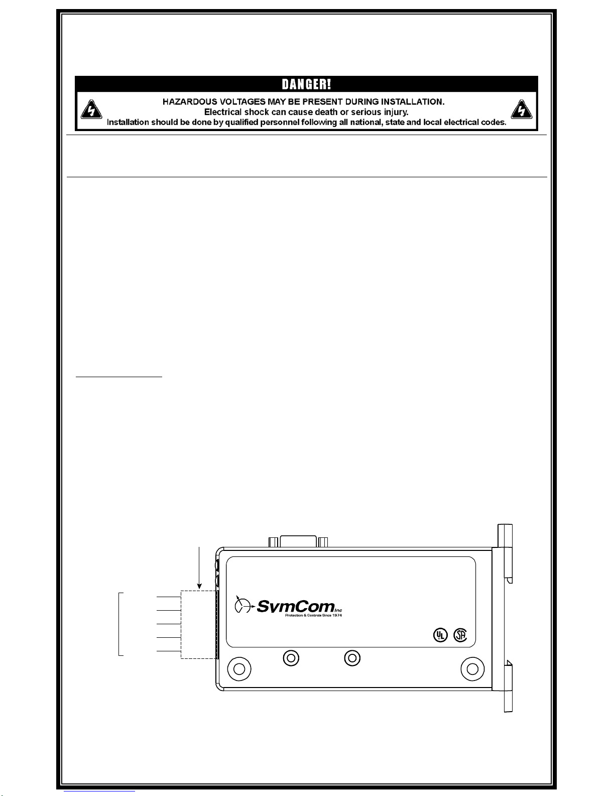
CONNECTIONS
1. Mount the CIO-777-PR in a convenient location in a properly rated enclosure. The CIO-777-PR
can be mounted to a back panel using screws or can be snapped onto DIN rail.
2. Connect the five Profibus wires to the 5-pin connector on the front of the CIO-777-PR Module.
24VDC should be connected to V+ and V-. Connect the other three wires to A, B and Shield.
3. The PBus LED indicates that communication is established between the CIO-777-PR and the
Profibus master, and OLC LED indicates communication is established with the 777-P Series
overload.
4. Connect the Profibus SUB-D connector to the Profibus network.
FIGURE 1: Typical Wiring Diagram
MODEL CIO-777-PR
PROFIBUS COMMUNICATIONS MODULE
PROGRAMMING GUIDE
DEPLUGGABLE
TERMINAL BLOCK
PROFIBUS
SUB-D CONNECTOR
PROFIBUS
NETWORK
VA
SHIELD
B
V+
IND. CONT. EQ.
LI STED
784X
¨
PROFIBUS NETWORK S TATUS
OVERLOAD COMM. S TATUS
PROFIBUS CommunicationCIO-E777-PR
SCREW TOR QUE RATING 0.5 Nm (5.0 in.-lbs.)
Phone: 800.894.0412 - Fax: 888.723.4773 - Web: www.clrwtr.com - Email: info@clrwtr.com
Page 2

DIAGNOSTIC INDICATOR LIGHTS
The unit is energized when power is applied between V+ and V- on the connector. The PBus and
OLC LEDs will flash until communication is established. The PBus communication status indicator
light will come on steady when a Profibus master is communicating with the unit. The OLC
communications status indicator light will come on steady when it is communicating to a 777-P
Series overload relay.
OPERATION
The CIO-777-PR Module is a DP-V0 device. Cyclical I/O is supported for the transfer of input and
output information.
PROFIBUS NETWORK CONFIGURATION
Cable Routing
Follow these general cable-routing guidelines:
Avoid areas of high temperature, moisture, vibration, or other mechanical stress.
Secure the cable where necessary to prevent damage.
Use cable ducts, raceways, or other structures to protect the cable.
Never route cables over, under or around sharp edges.
Avoid sources of electrical interference that can induce noise into the cable. Use the maximum
practical separation from such sources.
Maintain a minimum separation of 3.3 ft. (1m) from the following equipment:
o air conditioners and large blowers
o elevators and escalators
o radios and televisions
o intercom and security systems
o fluorescent, incandescent, and neon lighting fixtures
Maintain a minimum separation of 10 ft. (3m) from the following equipment:
o Line and motor power wiring
o Transformers
o Generators
o Alternators
Terminating Resistors
Profibus segments must be bus terminated as shown.
FIGURE 3: Bus Termination
390Ω
220Ω
390Ω
+5V
Li ne B
Li ne A
Data Ground
Phone: 800.894.0412 - Fax: 888.723.4773 - Web: www.clrwtr.com - Email: info@clrwtr.com
Page 3
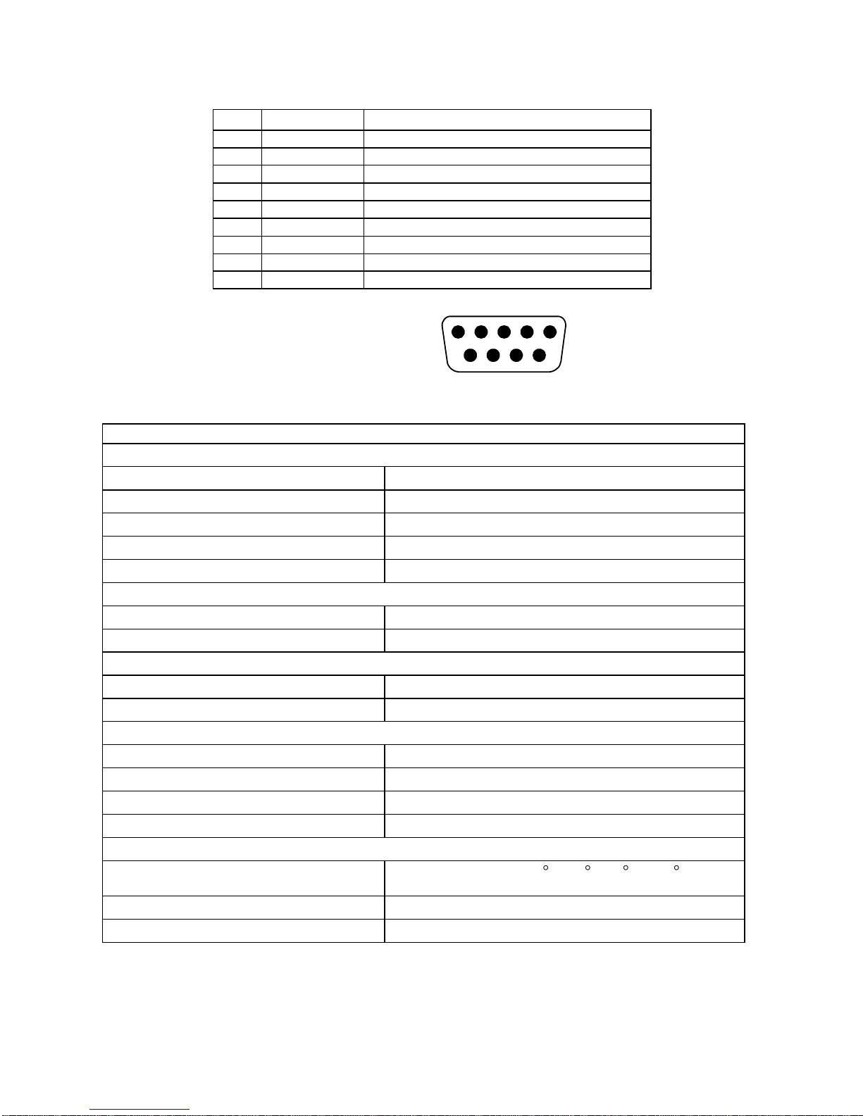
Profibus Cable
The Profibus Cable must be connected as follows:
Pin
Signal
Description
1
–––
–––
2
–––
–––
3
RxD/TxD-P
Receive/Transmit data; line B (red)
4
CNTR-P
Control of repeater direction
5
DGND
Data ground (reference voltage to VP)
6
VP-
Power supply +5V (e.g. bus termination)
7
–––
–––
8
RxD/TxD-N
Receive/Transmit data; line A (green)
9
-----
------
CIO-777-PR SPECIFICATIONS
Power Requirements
Voltage
12–24VDC
Current
150mA (max.)
Power
3.6 Watts (max.)
Weight
3 oz.
Enclosure
Polycarbonate
Terminal (depluggable terminal block)
Torque
4.5 in.-lbs. (max.)
Wire AWG
12–20 AWG
Safety Marks
UL
UL508 (File #E68520)
CSA
C 22.2
Standards Passed
Electrostatic Discharge (ESD)
IEC 1000-4-2, Level 3, 6kV contact, 8kV air
Radio Frequency Immunity, Radiated
159 MHz, 10V/m
Fast Transient Burst
IEC 1000-4-4, Level 3, 4 kV input power
Hi-Potential Test
Meets UL508 (2 x rated V +1000V for 1 minute)
Environmental
Temperature Range
Ambient Operating: -20 to 70 C (-4 to 158 F)
Ambient Storage: -40° to 80°C (-40° to 176°F)
Class of Protection
IP20, NEMA 1 (Finger Safe)
Relative Humidity
10-95%, non-condensing per IEC 68-2-3
1 2 3 4 5
6 7 8 9
FIGURE 3: 9-Pin Sub-D
Connector Pin Assignment
Phone: 800.894.0412 - Fax: 888.723.4773 - Web: www.clrwtr.com - Email: info@clrwtr.com
Page 4
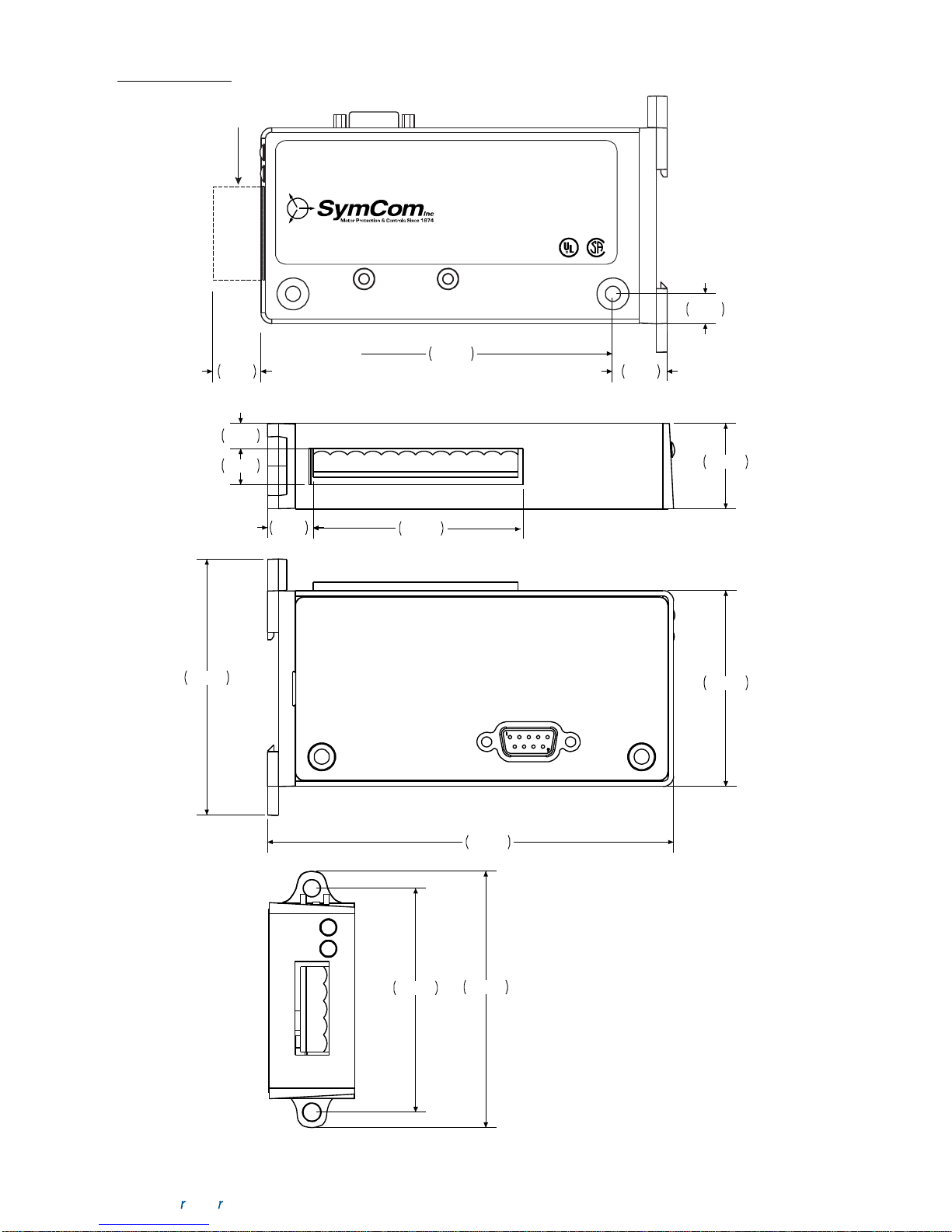
2.999
2.300
4.760
2.628
3.006
1.000
.535
3.500
.297
.420
3.750
.635.700
.350
DEPLUGGABLE
TERMINAL BLOCK
PROFIBUS
SUB-D CONNECTOR
IND. CONT. EQ.
LIS TED
784X
¨
PROFIBUS NETWORK S TATUS
OVERLOAD COMM. S TATUS
PROFIBUS CommunicationCIO-E777-PR
SCR EW T ORQUE R ATING 0.5 Nm (5.0 in-lbs. )
DIMENSIONS
Phone: 800.894.0412 - Fax: 888.723.4773 - Web: www.clrwtr.com - Email: info@clrwtr.com
 Loading...