

Page 1
INSTALLATION
INSTRUCTIONS
Rapid City, SD, USA, 02/2010
MODEL ALT-XXX-1-SW
Revision C1
II_ALT-XXX-1-SW_C1
2880 North Plaza Drive, Rapid City, South Dakota 57702
(800) 843-8848 · (605) 348-5580 · fax (605) 348-5685
Page 2

BE SURE POWER IS DISCONNECTED PRIOR TO INSTALLATION!
FOLLOW NATIONAL, STATE AND LOCAL CODES.
SymCom’s PumpSaver
commonly used in duplex pumping applications to balance the run time of two pumps (loads). The
voltage designation must be specified in the part number.
The ALT-XXX-1-SW gives the user the option to allow the unit to automatically select the load, to
balance the run time of the two loads, or to manually select Load 1 or Load 2. This gives the user the
option to force one load to be the lead at all times when one load has been removed for maintenance
or repair.
An additional feature is the ability to output to two remote indicator lights.
READ THESE INSTRUCTIONS ENTIRELY BEFORE INSTALLATION.
®
Model ALT-XXX-1-SW is designed to alternate between two loads. It is
CONNECTIONS
1. The ALT-XXX-1-SW requires an 11-pin socket part number OT11 (sold separately).
2. Mount the PumpSaver
If the location is wet or dusty, it should be mounted in a NEMA 4 or 12 enclosure.
NOTE: The ALT-XXX-1-SW can be connected in many different ways using many different
switching devices. The following is a typical configuration for alternating between two pumps
and two indicator lights. See Figure 2 for a typical wiring diagram showing the following
connections.
3. Connect one pump’s magnetic contactor coils (M1) between socket terminal 11 and L2 of
the power supply.
4. Connect the other pump’s magnetic contactor coil (M2) between socket terminal 9 and L2
of the power supply.
5. Connect the indicator light for M1 (LT1) between socket terminal 3 and L2 of the power
supply.
6. Connect the indicator light for M2 (LT2) between socket terminal 1 and L2 of the power
supply.
7. Connect the power supply L2 to socket terminal 8 and power supply L1 to socket terminal
4.
8. Connect the control switch device between the power supply L1 and the socket terminals
10, 2, and 6.
9. Plug the Model ALT-XXX-1-SW into the socket.
© 2010 SymCom, Inc. All Rights Reserved 2
®
socket in a convenient location in or near the pump control panel.
Page 3
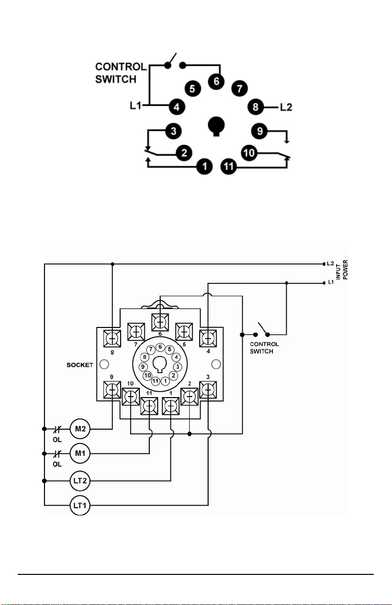
Figure 1: Pin-out Diagram
Figure 2: Typical Pump Control Wiring Diagram
© 2010 SymCom, Inc. All Rights Reserved 3
Page 4

SETTINGS
Figure 3: User-Selectable Options
The unit itself has one adjustable setting for load selection. Any additional configurations must be set
by connections to user-selected external switches.
To let the unit automatically select the load to be activated next, set the dial to “AUTO”. Turn the dial
to the selected load to allow only that specific load to be activated. This de-activates the other load if
it is currently activated. This allows one pump to be taken out of the circuit for repair or replacement.
Lock-out power to the ALT-XXX-1-SW before attempting to repair or replace
wiring or loads
OPERATION
Apply power to the system. Indicator lights on the unit will show which load is currently active.
Output to the corresponding remote light will also be activated.
When set to “AUTO”, the active load will continue to run until the control switch is opened. Each time
the control switch is opened, the output contacts will switch to activate the opposite load and light
the next time the control switch closes.
© 2010 SymCom, Inc. All Rights Reserved 4
INDICATOR LIGHTS STATUS
LD1 ON LOAD 1 ACTIVE
LD2 ON
Table 1: Diagnostic Indicator Lights
LOAD 2 ACTIVE
Page 5

TROUBLESHOOTING
SYMPTOM
Device is not functional
Only one load runs
when the control switch
closes. Device does not
alternate between the
two loads.
LIGHT
PATTERN
NO LIGHTS ON
ONE LIGHT ON
SOLUTION
Measure the line voltage. If the voltage is
below the minimum listed in the Specification
Table, the PumpSaver
power to operate its internal electronics. If the
voltages are correct, call SymCom at (800)
843-8848 or (605) 348-5580.
Check the adjustment knob setting on the ALTXXX-1-SW to make sure it is set to the AUTO
position.
®
does not have enough
Neither load runs.
ONE LIGHT ON
Check the control switch to make sure it is
closing properly. Check wiring between ALTXXX-1-SW and motor controls.
© 2010 SymCom, Inc. All Rights Reserved 5
Page 6

DIMENSIONS
*Use of the OT11-PC or RB11-PC octal socket, manufactured by Custom Connector Corp., is
required for the MotorSaver to qualify as a UL Listed device. The OT11-PC is 35mm DIN rail
compatible.
© 2010 SymCom, Inc. All Rights Reserved 6
Page 7

PUMPSAVER® ALT-XXX-1-SW SPECIFICATIONS
Functional Characteristics
Debounce Time Delay 1 second Input Characteristics Line Supply Voltage
ALT-100-1-SW 95-120VAC ALT-200-1-SW 190-240VAC Frequency 50/60Hz
Output Characteristics Output Contact Rating
Pilot Duty 480VA @ 240VAC General Purpose 10A @ 240VAC
General Characteristics Environmental
Ambient Operating Temperature Relative Humidity 10-95%, non-condensing per IEC 68-2-3 Maximum Input Power 5 W Standards Passed Electrostatic Discharge (ESD) IEC 61000-4-2, Level 3, 6kV contact, 8kV air Radio Frequency Immunity, Radiated 150 MHz, 10V/m Fast Transient Burst IEC 61000-4-4, Level 3, 3.5kV input power and
Surge Immunity IEC IEC 61000-4-5, Level 3, 4kV line-to-line; Level 4, 4kV
ANSI/IEEE C62.41 Surge and Ring Wave Compliance to a level
Hi-Potential Test Meets UL508
Safety Marks UL listed (OT11 octal socket
required) CE IEC 60947-6-2 Dimensions 2.330” H x 2.375” W x 4.125” D (with socket) Weight 9 oz Enclosure Polycarbonate Mounting Method Plugs into OT11 Socket; can be mounted to DIN rail
Wire Gauge 12-22 AWG Solid or Stranded Terminal Torque for P/N OT11 Socket 12 in. – lb
1
-40° to 70°C (-40° to 158°F)
controls
line-to-ground
of 6kV line-to-line
(2 x rated V +1000 V for 1 minute)
UL508 (File #E68520)
or surface mount
1
The ambient air temperature is the air temperature directly surrounding the product.
© 2010 SymCom, Inc. All Rights Reserved 7
Page 8

For warranty information, please see Terms and Conditions at
www.symcom.com
Visit us at www.symcom.com to see
our complete product listing!
Need something special?
Contact SymCom today
for your custom solution!
800-843-8848
© 2010 SymCom, Inc. All Rights Reserved 8
 Loading...