

#1
#2
L1 L2
INSTALLATION
INSTRUCTIONS
FOR SYM COM'S
DEVICE
L2
L1
MODEL ALT
BE SURE POWER IS DISCONNECTED PRIOR TO INSTALLATION!!
FOLLOW NATIONAL, STATE AND LOCAL CODES!
The Model ALT alternating relay is used to
alternate between two loads. It is commonly
used in duplex pumping applicati ons to
balance the runtime of both pumps. The
voltage must be specified in the ALT part
number—Table 1 identifies all available
Model ALTs.
ALT-24-S 20–26VAC, SPDT relay
ALT-24-X 20–26VAC, DPDT relay
ALT-24-S-SW 20–26VAC, SPDT relay w/ manual/automatic switch
ALT-24-X-SW 20–26VAC, DPDT relay, w/ manual/automatic switch
ALT-115-S 95–125VAC, SPDT relay
ALT-115-X 95–125VAC, DPDT relay
ALT-115-S-SW 95–125VAC, SPDT relay, w/ manual/automatic switch
ALT-115-X-SW 95–125VAC, DPDT relay, w/ manual/automatic switch
ALT-230-S 195-250VAC, SPDT relay
ALT-230-X 195–250VAC, DPDT relay
ALT-230-S-SW 195–250VAC, SPDT relay, w/ manual/automatic switch
ALT-230-X-SW 195–250VAC, DPDT relay, w/ manual/automatic switch
TABLE 1: ALT Model Numbers
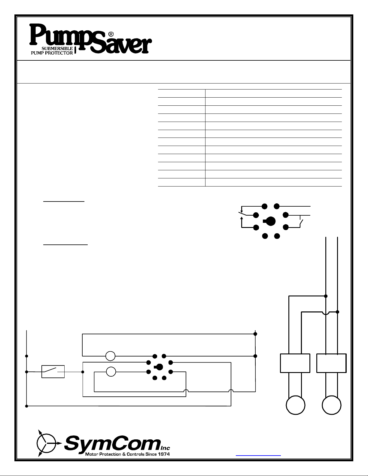
MODEL ALT-S
The Model ALT-S has a single-pole, double-throw output relay and is used in
single high-level float applications. When the float switch opens, the alternating
relay changes state forcing the other pump to run the next time the float closes.
23
14
58
76
CONNECTIONS (MODEL ALT-S)
1. Mount the Model OT08 octal socket in a convenient locati on inside the pump control panel.
2. Connect one of the pump's magnetic contactor coils (#1) between socket terminal 2 and L1 of the
power supply (see Figure 1).
3. Connect the other pump's magnetic contactor coil (#2) between socket terminal 8 and L1.
4. Connect the power supply L1 to socket t erminal 3 and L2 to terminal 4.
5. Connect socket terminals 1 and 5 to one side of the pilot device (pressure switch, float
switch or other isolated contact).
6. Connect the unconnected side of the pil ot device to L2.
7. Plug the Model ALT into the socket.
SUPPLY
PILOT
PRESSURE SWITCH,
FLOAT SWITCH OR
OTHER ISOLATED
CONTACT
FIGURE 1: Typical Wiring Diagram for the Model ALT-S
MAG. COIL
#1
MAG. COIL
#2
NC
C
NO
23
14
58
76
MAGNETIC
CONTACTOR
#1
PUMP
2880 North Plaza Drive, Rapid City, SD 57702
(800) 843-8848 · (605) 348-5580
www.symcom.com
MAGNETIC
CONTA CTOR
#2
PUMP
S1
L1
L2
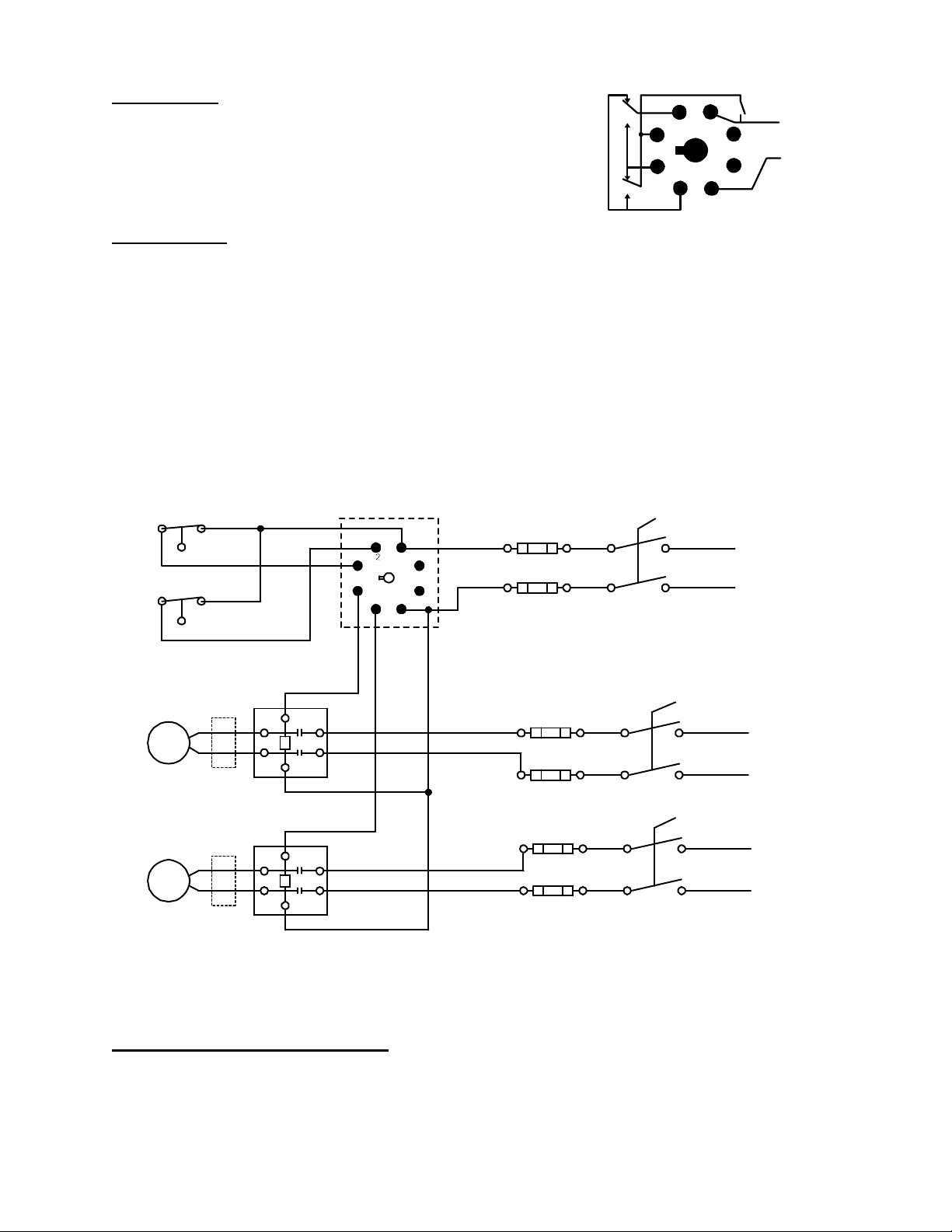
MODEL ALT-X
PILOT
MODEL ALT-X
OPTIONAL
The Model ALT-X has an internal double-pole, double-throw, cross-connected
relay and is used in dual high-level float applications. The pumps alternate as
in the ALT-S version, but the cross-connected relay configuration allows both
pumps to run simultaneously when both the lead and lag floats are closed.
2 3
1 4
7 6
58
CONNECTIONS (MODEL ALT-X)
1. Mount the Model OT08 octal socket in a convenient l ocation inside the pump control panel.
2. The control circuit should be separately fused to avoid disabling the control circuit when one pump is
disconnected for service.
3. Connect Pump #1’s magnetic contactor coil between socket terminal 8 and L2 of th e power supply.
4. Connect Pump #2’s magnetic contactor coil between socket terminal 7 and L2 of th e power supply.
5. Connect the LEAD pilot device, S1 (pressure switch, float switch or other i solated contact), between
socket terminals 1 and 3. Each time S1 opens, the relay changes state forcing the other pump to run
the next time the float closes.
6. Connect the LAG pilot devi ce, S2, between socket terminals 2 and 3.
7. Connect L2 of the power supply to socket terminal 6 and L1 to terminal 3.
8. Plug the Model ALT into the socket.
DEVICE
SUPPLY
LEAD
LAG
S2
PUMPSAVER® PUMP
PROTECTOR
PUMP
#1
MAGNETIC CONTACT ORS
PUMP
#2
OPTIONAL
PUMPSAVER® PUMP
PROTECTOR
23
1
8
F1
L1
4
5
67
1–2A TYPICAL SIZE
FOR CONTACTOR COILS
SIZE FOR INDIVIDUAL
PUMP APPLICATION
F2
F1 & F2:
F3
F4
F5
F6
F3–F6:
L2
L1
L2
MANUAL/AUTOMATIC SWITCH
The ALT is also available with a built-in switch (-SW option) that can be used to manually force one pump to run every
time the float closes. This is useful when a pump has been removed for repair or for test purposes. In the case of the
Model ALT-X-SW, the switch essentially forces one pump to be the lead pump, while still allowing the second pump to
run if both floats are closed.
FIGURE 2: T ypical W iring D iagram for the Model ALT-X
 Loading...