

INSTALLATION INSTRUCTIONS FOR SYMCOM'S
MODEL 777-LR-TS ELECTRONIC OVERLOAD RELAY, 2 - 10 AMPS
BE SURE POWER IS DISCONNECTED PRIOR TO INSTALLATION!!
FOLLOW NATIONAL, STATE AND LOCAL CODES!
READ THESE INSTRUCTIONS ENTIRELY BEFORE INSTALLATION.
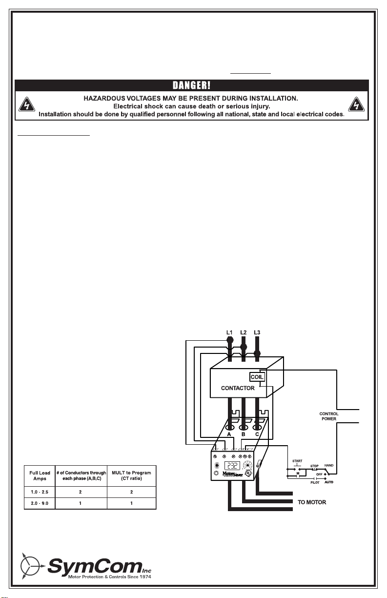
FIGURE 1: Typical Wiring Diagram
TABLE 1: Wiring Configuration
Based on Motor Amps
CONNECTIONS
1. Using the four corner tabs OR the DIN rail mounting bracket, mount the Model 777-LR-TS directly
above or below the magnetic contactor. To use the DIN rail bracket, hook the top clip first, then apply
downward pressure until the lower clip "clicks" onto the rail.
2. Insert the motor conductors through the round holes marked "A", "B", and "C." Terminate the
conductors at the line or load side of the magnetic contactor. Note: For motors with full load
amps less than 2.0 Amps, loop the conductors through the holes marked "A", "B", and "C"
according to Table 1 below. The rectangular holes behind the holes marked "A", "B" and "C"
are provided for wire looping (see Figure 1).
3. Connect the three-phase power from the line side of the contactor to "L1", "L2" and "L3".
First insert a #14 - #18 AWG wire into the top of the terminal marked L1 and tighten the screw on
the front of the overload relay. Then, connect the other end of the wire to the line side of the
contactor. Repeat these two steps for L2 and L3 (see Figure 1).
4. Connect the output relay to the circuitry to be controlled (see Figure 1). To control a motor,
connect the normally open contact in series with the magnetic coil of the motor starter as shown.
To sound an alarm, connect the normally closed contact in series with the alarm (not shown).
277 VAC
DISPLAY / PROGRAM
L3-L1L3-L1
L
B
E
+
O
V
AV
G
VG
T
L
1
-
L
2
L1-L2
L
2
L
3
L2-L3
C
N
T
C
E
A
A
G
AV
G
VG
R
R
U
RD2 UCTD
CUB
LV
MULT
UC
OC
HV
VUB
RD1TCGF
RUN
#RU / ADDR
RD3
#RF
MODE SELECT
L1 L2
L3
NO C NC
MODEL 777-LR
OVERLOAD RELAY
LOW RANGE, 2-10 AMPS
DISPLAY MESSAGE
RESET/
PROGRAM
800-843-8848SYMCOM, INC. RAPID CITY, SD
2880 North Plaza Drive, Rapid City,SD 57702 • (800) 843-8848
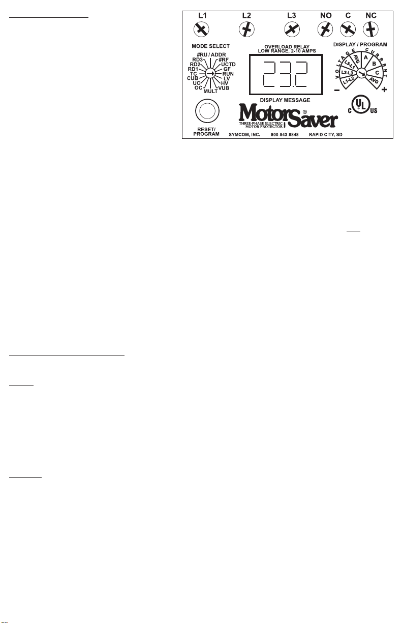
FIGURE 2: Unit Face and Display
PROGRAMMING
1. Select the feature to program by rotating the
"MODE SELECT" switch to the desired
position. The "MULT" setting must be
programmed before any of the current
settings to ensure proper display of actual
current setpoints. Therefore, SymCom
recommends programming the "LV" setting
first, then move clockwise through the
postions to complete the process.
2. Push and hold the “RESET / PR OGRAM”button.
3. Rotate the “DISPLAY / PROGRAM”adjustment to the desired setting of the feature as shown in the LED display.
4. Release the “RESET/PROGRAM” button.The Model 777-LR-TS is programmed when the button is released.
5. Continue steps 1-4 until all features are programmed.
NOTE: Some "MODE SELECT" positions are dual function such as the "#RU / ADDR" position. When
the "MODE SELECT" switch is pointed at "#RU / ADDR," y ou may view and program "#RU" and
"ADDR."
To view the two settings, rotate the "DISPLAY / PROGRAM" adjustment across its entire range. You will
see the "#RU" setting when the "DISPLAY / PROGRAM" adjustment is between approximately 7 o'clock
and 11 o'clock. You will see the "ADDR" setting when the "DISPLAY / PROGRAM" adjustment is
between approximately 11 o'clock and 5 o'clock.
To program "#RU" or "ADDR,# follow the programming instructions above. The "#RU" setting will only
be progrrammed when the "DISPLAY / PROGRAM" adjustment is between approximately 7 o’clock and
11 o’clock. Likewise, the "ADDR" setting will only be programmed when the "DISPLAY / PROGRAM"
adjustment is between approximately 11 o’clock and 5 o’clock. "ADDR" settings will be an "A" followed
by a number between 1 and 99.
SUGGESTED SETTINGS (Consult the Motor Manufacturer for their recommendations.)
[Be sure to read the programming example on page 5.]
LV/HV- The recommended settings for "LV" (low voltage) and "HV" (high voltage) depend on many
factors such as motor usage, motor size, environmental factors and tolerance of the motor. The
motor manufacturer should be consulted for "HV" and "LV" settings. However, the NEMA MG1
standard recommends that "LV" and "HV" be set to no more than ±10% of the motor's nameplate
voltage. The setting can be determined by multiplying the motor's nameplate voltage by the
recommended percent over and under voltage. (eg., The motor nameplate voltage is 230 V,
set "LV" to 0.9x230=207, set "HV" to 1.10x230=253) "LV" can not be set higher than "HV",
so "HV" may have to be adjusted higher before the proper "LV" setting can be programmed.
VUB/TS- "VUB" is the voltage unbalance trip point. The NEMA MG1 standard does not recommend
operating a motor above a 1% voltage unbalance without derating the motor.Voltage unbalance
is determined from the following formula:
% Voltage Unbalance = [(Maximum Deviation from the Average) / Average] x 100%
The NEMA MG1 standard also recommends against operating a motor above a 5% voltage
unbalance under any circumstances. Therefore, a setting of "5" is a good place to start but
SymCom recommends consulting the motor manufacturer for specific tolerances.
Note: A setting of "999" in this position will eliminate voltage unbalance and single phase protection.
"TS" allows the user to turn the temperature sensor trip function on or off. The 777-LR-TS will
only detect high temperatures when used with a *Subtrol®-equipped submersible motor.
*Subtrol is a registered trademark of Franklin Electric Co., Inc.
IND. CONT. EQ.
LISTED
784X
/TS
MODEL 777-LR-TS
4/03 - 2 -

TABLE 2: Trip Class Descriptions
MUL
T- "MULT" is the multiplication factor for determining true current settings and represents the
number of conductors passing through the main current windows marked "A", "B" and "C," or
current transformer ratio of external CTs. The appropriate number can be determined from
Table No.1 on page 1. "MULT" must be correctly programmed in order to accurately program the
current settings.
OC- Represents the manufacturer's maxim
um service factor amperage.
The "OC" (overcurrent)
setting depends on many factors such as motor usage, motor size, environmental factors and
tolerance of the motor. The motor manufacturer should be consulted for "OC" settings.
However, "OC" is typically between 110% and 125% of full load amperage (FLA).
UC- The "UC" (undercurrent) setting is typically set to 80% of full load amperage (FLA). The overload
relay with a "UC" setting of 80% of FLA will typically detect a loss of load for many pumps and
motors such as a dry well condition for submersible pumps. The "UC" setting may be set to 0.00
to disable undercurrent (loss of load) protection.
CUB- "CUB" is the current unbalance trip point. Most motor manufacturers recommend operating under
no more than 5% current unbalance, therefore, a setting of "5" is a good place to start. However,
your motor manufacturer should be contacted for exact settings.
Note: A setting of "999" in this position will eliminate current unbalance and single phase protection.
TC- "TC" designates the trip class for overload protection. The tr ip class defines the trip delay when
an overload is detected (see Table 2). Trip class is determined by the type of motor and
application. Your motor manufacturer should be consulted for the proper setting. The following
table shows the trip class and a general description of the applications.
RD1- "RD1" is the rapid cycle timer. It will engage when the motor is first powered-up or after the motor
controls shut down the motor. An "RD1" setting of 20-30 seconds will generally protect the motor
from rapid, successive power outages or short cycling caused by the motor controls. A setting
of 0 seconds will allow the motor to start immediately after power-up or after a normal shutdown.
RD2- "RD2" is the restart delay after the overload relay trips on current unbalance, single phasing and
overload (if "oc" is programmed in "#RF"). This delay allows the motor to cool down after
experiencing the above faults. It is also known as a motor cool down timer. Your motor
manufacturer should be contacted to determine this setting. Under normal circumstances, a
setting of 5-10 minutes will give the motor enough time to cool down between faults.
RD3- "RD3" is the restart delay after an undercurrent. It is also known as a dry well recovery timer and
is usually used in submersible pumping applications. The setting of "RD3" depends on the
recovery time of the water well and varies widely from application to application.
ssalCpirTnoitpircseDnoitacilppA
5
rosuoenatnatsnitsomlaerasemitnoitareleccaerehwsrotomrewopesrohlanoitca
rfllamS
.deriuqererasemitpirtkciuqylemertxeerehw
01
larenegdnaspmupelbisrembus,srosserpmoc,srotomtnaregi
rfercitemreH)pirTtsaF(
.sdnoces4nahtsselnideepsdetarhcaertahtsrotomesoprup
51 .snoitacilppadezilaicepsni
atreC
02 .gnittessihtybdetcetorpeblliwsrotomesopruplarenegdetar-AMENtsoM)pirTdradnatS(
03 .sdaolaitrenihg
ihro)sdnoces01>(semitnoitareleccagnolhtiwsrotoM)pirTwolS(
xiferPJ
sihT.noitcetorpmajelbanelliwxiferPJeh
thtiwsessalcpirtehtfoynagnimmargorP
dnoces-2asedivorpdnastratsrotomehtretfaetunim1delbanesinoitcetorpl
anoitidda
.ssalcpirtfosseldrager,AFS%004gnideecxesrotomrofemitpirt
- 3 - 4/03

10000
1000
100
10
0 300 400 500
% of OC Setting
Trip Time (Seconds)
600 700 800 900 1000
Class 10
Class 30
Class 20
Class 15
Class 5
200100
1
Overload Trip Classes
FIGURE 3: Overload Trip Classes
#RU- "#RU" is the number of successive restart attempts allowed after an undercurrent fault before the
overload relay requires manual reset. A setting of "0" is manual reset and a setting of "A" is
continuously automatic reset.
ADDR- "ADDR" is the address setting for RS485 communications. Available settings are from A01 - A99.
This setting is programmed on the right half of the PROGRAM/DISPLAY adjustment
(see programming instruction note for explanation of dual function settings). You may ignore this
setting if RS485 communications are not used.
#RF- "#RF" is the number of successive restart attempts allowed after a current unbalance, single
phasing or overload fault. The following settings are available: "0", "1", "oc1", "2", "oc2", "3",
"oc3", "4", "oc4", "A", and "ocA". A setting which includes "oc" will allow the overload relay to
automatically reset after an overload fault (eg., a setting of "oc2" will allow the overload relay to
reset 2 times after an overload condition before locking out if an overload condition is detected
immediately after each of those two times.) A setting which does not include "oc" requires a
manual reset for all overload faults. A setting of "0" is manual reset and a setting of "A" is
continuously automatic.
UCTD- "UCTD" is the undercurrent trip delay timer. This setting represents the maximum time that the
Model 777-LR-TS will tolerate an under current condition. Typically, UCTD is set to 2 - 4 seconds.
GF- "GF" is the ground fault protection amperage threshold. This setting detects a leakage current to
ground and signals an insulation breakdown in the system. The "GF" setting should be some
where between 10% and 20% of the full load motor current. Short circuit protection is provided
by separate branch protective devices such as circuit breakers or fuses.
Ground fault protection is a Class II ground fault protector and should not be used for personnel
safety, but can be used to indicate motor degradation for maintenance purposes.
4/03 - 4 -

PROGRAMMING EXAMPLE
Motor To Be Protected: 3-phase, 460 Volt, 1/2 Hp submersible pump with a full load amperage of
1.2 A and maximum service factor amps of 1.6.
Use the following calculations and reasoning to determine the appropriate settings for this application.
LV- 460 x 0.90 = 414
HV- 460 x 1.10 = 506
VUB/TS- Manufacturer suggests 5. Turn on temperature sensor fault detection.
MULT- From Table No.1, MULT = 2, 1 loop of main conductor
OC- Service Factor Amperage = 1.6
UC- FLA x 0.80 = 1.2 x 0.80 = .96
CUB- Manufacturer suggests 5
TC- From Figure No. 3, for this (and most) submersible pumps, TC = 10 (fast trip)
RD1- To protect the pump from rapid cycling, RD1 = 60
RD2- Since the motor is small and submerged in water, the motor will generally cool down quickly.
RD2=5
RD3- The well history shows that it will fully recover in 2 hours. RD3 = 120
#RU- In this application, we know that the well will eventually recharge itself, #RU = A.
#RF- This well is known for sand to jam the impeller, therefore "oc" should be included so that the
pump will attempt to automatically restart after an overloaded condition. History shows that 2
or 3 starts and stops usually clears the sand out of the impeller. #RF = oc2 or oc3.
UCTD- This well may become airlocked on startup, but will usually re-prime itself in 5 seconds or less.
UCTD = 10
GF- Because it may take several days to get a new pump and schedule for a driller to remove and
replace the pump, GF setting of 10% of full load amperage will give the well o wner enough time
to prepare for pump replacement. GF = 1.2 x 0.15 = 0.18
MUL
TI-FUNCTION SYSTEM DISPLAY
The output display can show various system operating parameters:
• Average Voltage • Average Current
• L1-L2 Voltage • L1 Current (A)
• L2-L3 Voltage • L2 Current (B)
• L3-L1 Voltage • L3 Current (C)
When the "MODE SELECT" switch is in the "RUN" position, the LED will display one of the above operating parameters. To select or change the displayed parameter, turn the "DISPLAY / PROGRAM" adjustment
to the desired position as shown on its label.
The multifunction display also announces system faults such as low voltage, high voltage, single phasing,
voltage unbalance, current unbalance, and reverse phasing errors. Any time the "MODE SELECT" switch
is in the "RUN" position, the "RESET/PROGRAM" button may be pushed to view the last fault which
occurred. The table below shows the possible messages.
egasseMdeyalpsiD gninaeM
cotnerrucrevOnodeppirT
PSgnisahPelgniSnodeppirT
buecnalabnUtnerruCroegatloVnodeppir
T
cutnerrucrednUnodeppirT
FC)ylnOtupnIegatloVØ3(eruliaFrotcatnoCnodeppirT
FrGtluaFdnuorGnodeppirT
IHegatloVhg
iHnodeppirT
oLegatloVwoLnodeppirT
Pr )ylnOtupnIegatloVØ3(.detratsfidrawkcabnuryamrotomruoY.desreverneebev
ahsesahpgnimocnI
FFo.ecruosetomeramorfdeussisawdnammocpotsA
toH.rotommorflangiserutarepmethgihnodeppirT
TABLE 3: Displayed Messages
- 5 - 4/03

COMMUNICATIONS PORT / REMOTE RESET
The Model 777-LR-TS comes standard with a 9-pin sub-D connector for remote communications.
The Model 777-LR-TS supports RS-485 communication standard. This standard allows up to 99 777-LR-TS'
to be controlled and monitored from a single remote personal computer. NOTE: An RS485MS-2W
module and software is required to operate the communications bus.(Refer to RS485MS-2W Installation
Instructions for more information on this subject.)
The communications port also provides connections for remote reset as shown below.
OPERATION
Once the overload relay has been programmed, turn the "MODE SELECT" switch to the "RUN" position.
The LED display will flash "RUN" alternatively with a number representing the par ameter indicated by the
"DISPLAY / PROGRAM" adjustment. After the period of time programmed into RD1, the output contacts
will close and the value of the parameter indicated by the "DISPLAY / PROGRAM" adjustment will appear
on the LED display.
If a message other than those indicated above is shown on the LED display, see the
TROUBLESHOOTING section to diagnose the problem.
TROUBLESHOOTING
If you need further assistance, call us at 1-800-843-8848...we'd be happy to help.
5432
6789
1
Normally Open Push Button
MELBORPNOITULOS
yalpsiD.tratstonlliwtinuehT
/YALPSID"ehthtiw"Pr"setanretla
retemaraphctiws"MARGORP
.eulav
y
napaws,putratslaitiniehtsisihtfI.desahpesrevererastupniegatlovehT
fI.melborpehttcerrocot"3L"ro,"2L","1L"otdetcennocsdaelehtfoowt
neebsahmetsysrewopeht,gninnurylsuoiverpneebsahyalerdaolrevoeht
.senilrewopgn
imocniehtfoecneuqesesahpehtkcehC.desahpesrever
morf"3L"dna,Bmorf"2L",Aesahprotcudnocmorfdepatebtsum"1L":etoN
.snoitacinummocetomernostnemerusaemrotcafrewoptcerrocrfC
yalpsiD.tratstonlliwtinuehT
"oL"ro,"IH",
"Bu","PS"setanretla
"MARGORP/YALPSID"ehthtiw
.eulavretemaraphctiws
,"VH","BUV"ehtnidemmargorpstimilehtnihtiwtonsiegatlovgnimocniehT
ehtdaerothctiws"MARGORP/YALPSID"ehttsujdA.sgnittes"VL"dna
dnamelborprewopgn
imocniehttcerroC.seulavegatlovenilgnimocni
.tcerrocerayehtyfirevotstimildemmargorpkcehc
ro,"Bu","PS"set
anretlayalpsiD
".NUR"htiw"co"
sidnayalpsidDELehtnonwohstluafehtnodeppirtsahyalerdaolrevoehT
.gnitratsererofeb"2DR"nwodgnimit
".NUR"htiw"cu"setanretlayalpsiD
"3DR"nwodgnimitsidnatnerrucrednunodeppirtsahyalerd
aolrevoehT
sihtrofnoitidnoclamronatonsitnerrucrednufI.gnitratsererofeb
.cte,stlebnekorb,stfahsnekorbrofkcehc,noitallatsni
,"PS"dilosagniwohssiyalpsiD
."toH"ro,"co","Bu"
deriuqersiteserlaunamdnanwohstluafehtn
odeppirtsahtinuehT
rofmetsysehtkcehC."FR#"nignittesdemmargorpehtfoesuaceb
ro,gnitaehrevo,daolrevo,esahp
elgnisehtecudorpdluowtahtsmelborp
.majaekiltluafecnalabnutnerruc
".cu"dilosagniwohssiyalpsiD
esuacebderi
uqersiteserlaunamadnatnerrucrednunodeppirtsahtinuehT
aecudorpdluowtahtsmelborprofmetsysehtkcehC".UR#"n
ignittesehtfo
.diuqilfotuosipmuparotlebnekorbaekildaolfossol
".FC"dilosagniwohssiyalpsiD
elgnistonsawtub
,tnerrucehtfognisahpelgnisanodeppirtsahtinuehT
.gniriwesoolrostcatnocdegamadrofkcehC.rewopgnimocniehtybdesahp
".FrG"dilosagniwohssiyalpsiD
neebsaheulav"FG"demmargorpehtnahtretaergtnerructluafdnuorgA
.nwodka
erbnoitalusnirofrotomehtkcehC.detceted
"NUR"htiw"toH"setanretlayalpsiD .ST-RL-777ehtotlangisagnidnessid
nadetaehrevosahrotompmupehT
4/03 - 6 -

- 7 - 4/03
SPECIFICATIONS 777-LR-TS
Input Voltage 200 - 480 VAC, 3-phase (Standard)
(500-600 VAC, 3-phase Available)
Frequency 50 - 60 Hz
Motor Full Load Amp Range 1 - 9 Amps, 3-phase
Programmable Operating Points Range
LV - Low Voltage Threshold 170V (450V*) - HV Setting
HV - High Voltage Threshold LV Setting - 528V (660V*)
VUB - Voltage Unbalance Threshold 2 - 15% or 999%
TS - Temperature Sensor Fault Trip On or Off
MULT - # of Loops 1 or 2 Loops
OC - Overcurrent Threshold (2.0 - 10.0A) / MULT
UC - Undercurrent Threshold (0, 1.0 - 9.8A) / MULT
CUB - Current Unbalance Threshold 2 - 25% or 999%
TC - Overcurrent Trip Class ** 5, J5, 10, J10, 15, J15, 20, J20, 30, J30
RD1 - Rapid Cycle Timer 0, 2 - 500 Seconds
RD2 - Restart Delay After All Faults Except
Undercurrent (Motor Cool Down Timer)
2 - 500 Minutes
RD3 - Restart Delay After Under Current
(Dry Well Recovery Timer)
2 - 500 Minutes
#RU - Number of Restarts After Undercurrent 0, 1, 2, 3, 4, A (Automatic)
ADDR - RS485 Address
A01 - A99
#RF - Number of Restarts After All
Faults Except Undercurrent ***
0, 1, oc1, 2, oc2, 3, oc3, 4, oc4, A, ocA
UCTD - Undercurrent Trip Delay 2 - 60 Seconds
GF - Ground Fault Current Threshold (0.3 - 2.0A) / MULT or OFF
Physical Specifications
Output Contact Rating (Pilot Duty) SPDT 480 VA @ 240 VAC
Transient Protection (Internal) 2500 V for 10 mSeconds
Accuracy
Voltage ±1%
Current ±3% (<10.0 Amps Direct)
Timing 5% ± 1 Second
Repeatability
Voltage ±0.5%
Current ±1% (<10.0 Amps Direct)
Temperature Range 0 - 70 °C
Dimensions 3.0" H x 5.1" D x 3.6" W
Power Consumption 5 Watts (Max.)
Weight
1.2 lbs.
NOTES: SymCom's Overload Relay can be preprogrammed prior to installation by applying
120 VAC between the L1 and L2 terminals.
*575 Volt Model.
**If J Prefix is displayed in trip class setting, jam protection is enabled.
***If "oc" is displayed in the #RF setting, then overcurrent will be included as a normal fault
and the relay will automatically restart after RD2 expires, otherwise, manual reset is required
after an overcurrent fault.
Visit our website at www.symcominc.com for our
complete catalog and new product listings!

2880 North Plaza Drive, Rapid City, SD 57702 • (800) 843-8848
Clearing Last F
ault
The last fault stored can be cleared on the MotorSaver®.
This procedure is outlined as follows:
1. Rotate the Mode Select Switch to ‘GF’.
2. Press and hold the Reset/Program Button. Adjust the Display/Program adjustment until cLr appears
on the display. Release the Reset/Program Button.
To verify the last fault was cleared, place the Mode Select switch in the Run position. Then press and
hold the Reset/Program Button, cLr should be on the display.
Tamper Guard
The MotorSaver®can be protected from unauthorized program changes by locking in the setpoints.
This procedure is outlined as follows:
1. Rotate the Mode Select switch to ‘GF’.
2. Rotate Display/Program adjustment fully clockwise.
3.Press and hold the Reset Button. Adjust the Display/Program adjustment until ‘Loc’ appears in the display.
4. Release the Reset Button.
5.Turn Mode Select switch to ‘run’.
The program is now locked, but all settings can be viewed.The unit can be unlocked by following the
procedure above except step three. This step should say:Press and hold the Reset Button.Adjust the
Display/Program adjustment until ‘unL’ appears in the display.
SymCom Warrants its microcontroller based products against defects in material or workmanship for a
period of five (5) years from the date of manufacture. All other products manufactured by SymCom shall
be warranted against defects in material and workmanship for a period of two (2) years from the date of
manufacture. For complete information on warranty, liability, terms, returns, and cancellations, please
refer to the SymCom Terms and Conditions of Sale document.
Visit our website at www.symcominc.com
for our complete catalog and new product listings!
 Loading...