

Symcom 777-KW/HP, 777-LR-KW/HP, 777-575-KW/HP, 777-HVR-LR-KW/HP, 777-HVR-KW/HP Installation Guide
ALLATION INSTRUCTIONS FOR
MODELS 777-KW/HP
INST
, 777-LR-KW/HP,777-575-KW/HP,
777-HVR-LR-KW/HP, 777-HVR-KW/HP
POWER MONITOR/MOTOR PROTECTION RELAY
BE SURE POWER IS DISCONNECTED PRIOR TO INSTALLATION!
FOLLOW NATIONAL, STATE AND LOCAL CODES!
READ THESE INSTRUCTIONS ENTIRELY BEFORE INSTALLATION.
The Model 777-KW/HP is a solid-state power monitor/motor protection relay. It is fully-programmable
for customized protection. It is designed to protect three phase systems operating on voltages from
190 to 480 VAC (500-600VAC for 777-575-KW/HP). The output relay is a Form C contact, which can
control a contactor or other device within the output relay contact rating. The unit can be programmed
prior to installation by applying 120VAC to terminals ‘L1’ and ‘L2’ (except 777-575-KW/HP and
777-HVR-KW/HP). The unit can NOT be tested for proper operation using this voltage. For testing
purposes, three phase power needs to be used with a minimum voltage of 190VAC
(450VAC for 777-575-KW/HPand 777-HVR-KW/HP).
CONNECTIONS
1. Disconnect power and verify power is off.
2. Using the four corner tabs or the DIN rail mount, mount the 777 directly above or below the
contactor. To use the DIN rail mount, hook the top clip first then apply downward pressure
until the lower clip ‘clicks’ onto the rail.
3. A) For amperage ranging from 25-90 amps (2-9 Amps -LR types), insert the motor
conductors through the holes marked ‘A’, ‘B’, and ‘C’. Make certain that the conductor through
each hole corresponds to the right motor conductor, i.e. the ‘A’ phase conductor should go through
the ‘A’round hole. See Figure 1 for a typical wiring diagram.
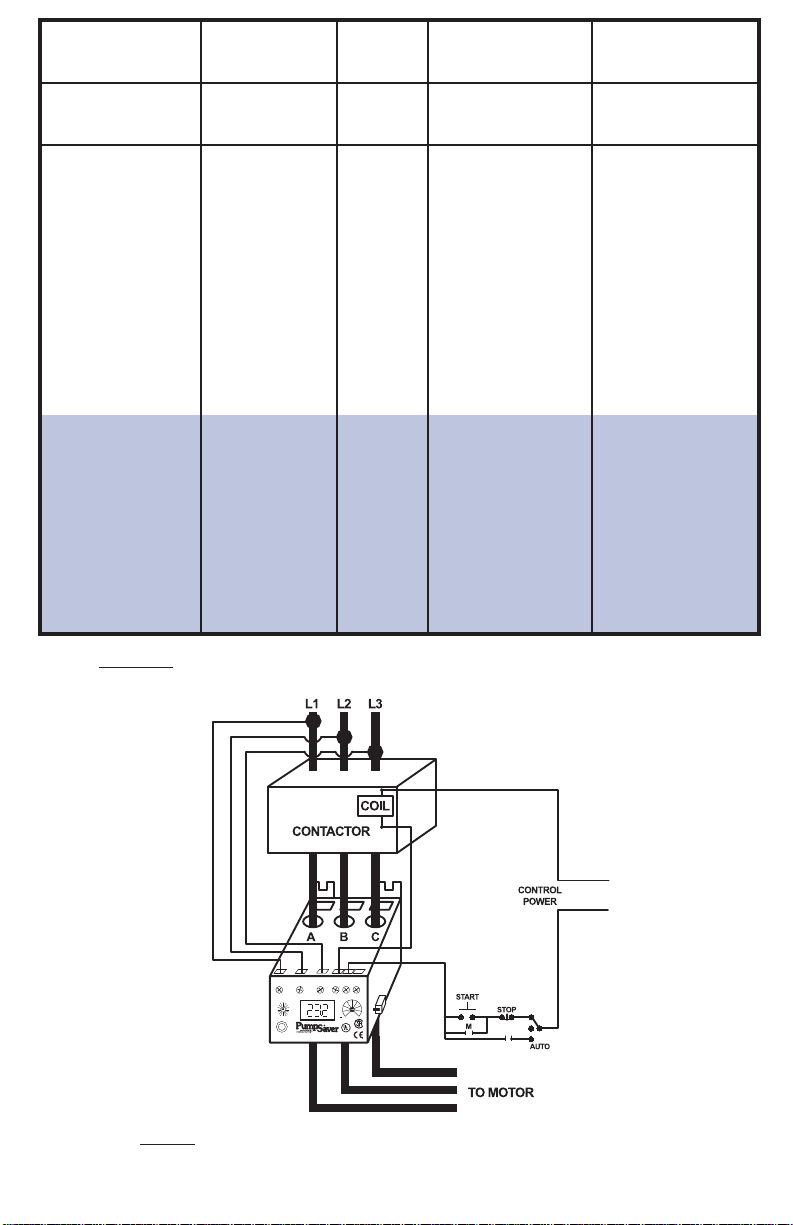
B) For amperage less than 25 amps, loop the motor conductors according to Table 1.
Figure 3 shows an example of the looping required for current ranging from 8.1 to 12 amps (MULT=3).
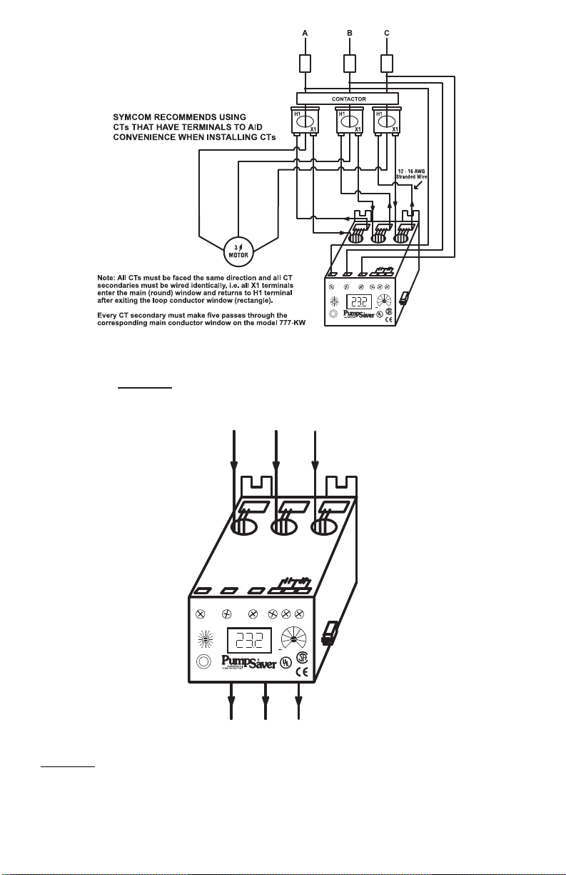
C) For amperage greater than 90 amps, external CT’s (current transformers) are required.
SymCom recommends CT’s with terminals be used for ease of installation. All CTsecondaries
must make five passes through the round holes on the PumpSaver. See Figure 2 for a typical
wiring diagram using external CT’s.
NOTE: Pay close attention to this diagram to eliminate any power factor errors that will create
errors in the horsepower measurements.
4. Connect the three phase power from the line side of the contactor to ‘L1’, ‘L2’, and ‘L3’ terminals
using 12-18AWG copper wire (See Figure 1). Figure 1 is drawn for a power system wired in
“ABC” phase sequence. For power systems with “ACB” phase sequence, switch L1 and L3
input.
connections on 777-KW
5. Connect the control circuit wires to the appropriate terminals. The relay is a fail safe design
so the ‘NO’ contact should be in series with the coil on the contactor for motor control
(see Figure 1). For alarm circuits, the ‘NC’ contact is in series with the alarm circuitry.
Visit our website at www
/HP
.symcominc
.com for our
complete catalog and new product listings!
2880 North Plaza Drive, Rapid City, SD 57702 • (800) 843-8848
L1 L2 L3 NO C NC
MODEL 777-KW/HP
OVERLOAD RELAY 20-90A
RESET/
PROGRAM
RD3
#RF
VUB
OC
#RU/ADDR
MULT
RD2 PWS
HV
LPS
RD1
CUB
GF
LV
TC
RUN
DISPLAY / PROGRAM
MODE SELECT
SUITABLE 10 KA RMS, 600 VAC MAX
SYMCOM INC. 800-243-8848 RAPID CITY
, SD
®
IND. CONT. EQ.
LISTED
784X
LR46510
L3-
L1
L
E
+
O
V
HP
T
L1-
L2
L2-
L3
N
T
C
E
B
A
C
KW
A
G
R
R
W
R
E
P
O
U
Model
Full Load Amps
# of Loops
# of Conductors
through A, B and C
MULT to Program
(CT Ratio)
777-XXX-LR-KW/HP
777-KW/HP
777-HVR-KW/HP
777-575-KW/HP
External CTs required.
See wiring diagram for
external CTs.
able 1: Wiring Configuration Based on Motor Full Load Amps
T
1 - 2
2 - 9
2 - 2.5
2.5 - 3
3 - 3.5
3.5 - 4
4 - 5
5 - 6
6 - 8
8 - 12
12 - 25
25 - 90
80 - 110
110 - 160
160 - 220
220 - 320
320 - 420
400 - 520
480 - 600
560 - 800
1
0
9
8
7
6
5
4
3
2
1
0
4
4
4
4
4
4
4
4
2
1
10
9
8
7
6
5
4
3
2
1
5
5
5
5
5
5
5
5
2
1
10
9
8
7
6
5
4
3
2
1
100 (100:5)
150 (150:5)
200 (200:5)
300 (300:5)
400 (400:5)
500 (500:5)
600 (600:5)
800 (800:5)
Figure 1: Typical Wiring Diagram for FLAof 26-90 (“ABC” phase sequence*)
- 2 -
*For input power configuration of “ACB” phase sequence, invert the L1 and L3 terminals on the 777-KW/HP
02/04
.
L1
L2 L3 NO C NC
MODEL 777-KW/HP
OVERLOAD RELAY 20-90A
RESET/
PROGRAM
DISPLAY / PROGRAM
MODE SELECT
SUITABLE 10 KA
RMS, 600 VAC MAX
SYMCOM INC. 800-243-8848 RAPID CITY, SD
®
IND. CONT. EQ.
LISTED
784X
LR46510
/HP.
RD3
#RF
VUB
OC
#RU/ADDR
MULT
RD2 PWS
HV
LPS
RD1
CUB
GF
LV
TC
RUN
L3-
L1
L
E
+
O
V
HP
T
L1-L
2
L2-
L3
N
T
C
E
B
A
C
KW
A
G
R
R
W
R
E
P
O
U
Figure 2: Typical Wiring Diagram Using External CTs.
L1 L2 L3 NO C NC
MODEL 777-KW/HP
OVERLOAD RELAY 20-90A
RESET/
PROGRAM
DISPLAY / PROGRAM
MODE SELECT
SUITABLE 10 KA RMS, 600 VAC MAX
SYMCOM INC. 800-243-8848 RAPID CITY, SD
®
IND. CONT. EQ.
LISTED
784X
LR46510
RD3
#RF
VUB
OC
#RU/AD
DR
MUL
T
RD2 PWS
HV
LPS
RD1
CUB
GF
LV
TC
RUN
L3-L
1
L
E
+
O
V
HP
T
L1-
L2
L2-L
3
N
T
C
E
B
A
C
KW
A
G
R
R
W
R
E
P
O
U
Figure 3:
Looping Example Showing Three Conductors (MUL
(No other necessary connections are shown.)
- 3 -
T=3 from T
able 1)
02/04

PROGRAMMABLE PARAMETERS
The programmable parameters are the parameters which the user MUST program to provide the correct
protection for the application.
All parameters are actual values except for the “VUB” and the “CUB” settings.
These are programmed as percentages. The range these parameters can be programmed to is found on
the electrical specifications on page 11. See page 7 for programming examples.
LV/HV - The recommended settings for LV (low-voltage) and HV (high-voltage) according to the NEMA
MG1 standard are ±10% of the motors nameplate voltage. For other settings the motor
manufacturer should be contacted. Example: The motor nameplate voltage is 230 volts. If we
take 90% and 110% of 230 we get 0.9 x 230= 207 volts for the LV setting and 230 x 1.1= 253
volts for the HV setting. These parameters are based on the average voltage going to the motor.
VUB - VUB (voltage unbalance) is factory set at 6%. The NEMA MG1 standard says a motor should not
be operated above a 1% voltage unbalance without DERATING the motor. Most utility supplied
power sources have a difficult time sustaining a 1% VUB. The motor manufacturer should be
consulted for an exact VUB setting. A setting of 999 for VUB will disable the VUB protection and
SP (single phase protection).
The VUB is calculated as follows:
%VUB = [(Maximum deviation from the average)/Average] x 100%
Example:Measured line-line voltages = 203, 210, and 212, so the average = (203+210+212)/3 = 208.3,
the maximum deviation from the average is the biggest difference between the average voltage
(208.3) and any one voltage reading, 212-208.3 = 3.7, 210-208.3 = 1.7 and 208.3-203 = 5.3,
therefore the maximum deviation from the average is 5.3. The VUB is then = 5.3/208.3 x 100= 2.5%
MULT - MULT (multiplier) setting is found from table 1. The MULT setting is determined by the current the
unit will be monitoring. This allows the unit to display the correct current. Changing this setting will
also change the “OC”, and “GF” set points.
OC - OC (overcurrent) is usually set at the service factor amperage (typically 100-115% of motor FLA)
of the motor, which is determined by the motor manufacturer. If any one leg of current exceeds the
oc setting, the unit will follow its overload trip curve. (see Figure 4).
LP- LP (low power setting) is used to shut down the motor or pump on an underload condition.
Setting LP to 0 disables the underload trip feature. LP is set in either kilowatts (KW) or
horsepower (HP) depending on the PWS setting. NOTE: PWS must be set before setting LP.
HP- HP (high power setting) is used to shut down the motor or pump on an overpower condition.
The High Power trip uses the underload trip delay and dry well recovery timer (RD3) to delay trips
and restarts. The HP and underload trip delay settings can only be adjusted from the SymCom
Solutions software or another software utility that can send Modbus write commands.
The 777-KW/HP is shipped from the factory with this feature disabled.
CUB - CUB (current unbalance) is factory set to 7%. SymCom recommends the motor manufacturer be
contacted for an exact setting. The CUB is calculated the same way the VUB is determined above.
The CUB protection can be disabled by programming a 999 in this setting. This will disable current
unbalance protection and current single phasing protection.
TC - TC (trip class) is the parameter used to determine when the unit will trip when an overload
condition is detected. For standard motors, the
able 2 and Figure 4 show the range of TC settings and
should be contacted for exact
TC settings.
T
TC is typically set at 20.
The motor manufacturer
trip times.
02/04
- 4 -

RD1 - RD1 (restart delay one) is the rapid cycle timer in seconds. This timer is initiated when power is
Run time
Next Restart
Delay (min)
Starts/Hr
> 1hr 6 10
30 min - 59.99 min 15 4
15 min - 29.99 min 30 2
< 15 min 60 1
first applied to the unit. If everything is okay (voltages are within the programmed limits and no SP
or RP condition exists), after power is applied to the device and the RD1 time expires, the output
relay will energize (the NO will close and the NC will open). Typically, this is set to 20-30 seconds.
This will provide adequate protection for successive power outages or short cycling caused by
other motor controls. This timer is also initiated when another control shuts the motor off (current
goes to zero). If the user does not want the units’ relay to de-energize when another control shuts
the motor off, then RD1 should be set to zero. This will also assure that when an alarm circuit is
used, an alarm will sound only when there is a true problem or when power is lost.
RD2 - RD2 (restart delay two) is the restart timer, in minutes, used when the unit has shut off due to a
current unbalance, current single phasing, or an overload condition (if “oc” is the prefix to the
number in #RF, see #RF description). This timer is known as a motor cool down timer. A setting of
5-10 minutes will give most motors adequate time to cool down after an overload condition. The
motor manufacturer should be contacted for an exact value.
RD3- Restart Delay 3 (Dry Well Recovery Timer) RD3 can be set from 2-500 minutes or to ‘A’ to enable
the Automatic Dry Well Recovery Calculator. The RD3 timer causes a restart delay after an under
load (LP) trip.
The Automatic Dry Well Recovery Calculator allows the 777 to automatically select a restart delay
based on the run time of the last run cycle. Table 2 shows the next restart delay vs. run time.
In general a longer run time produces a shorter restart delay. This feature allows the 777 to
optimize running and rest times automatically.
Table 2: State Table
#RU - The #RU/ADDR is a dual function setting. #RU can only be set to 0, 1, 2, 3, 4, or A. ADDR
settings have the following format: Axx. The “xx” is any number combination from 01-99. This is
how to identify which parameter is being programmed. The #RU settings cover from the 7 o’clock
position to the 11 o’clock position. ADDR settings start after the 11 o’clock position. #RU (# of
restarts after an underload) is the number of restarts after a low power trip condition before the
unit locks and requires a manual restart. This counter will be cleared one minute after start-up if
the unit does not trip again on LPR. Asetting of zero means no automatic restarts after an under
load. Asetting of “A” means the unit will always automatically restart after an underload.
ADDR - ADDR (address) is the RS485 address of the particular device. This is only used when
communicating with an RM-2000 (set ADDR=A01), RM-1000, a PLC, or PC. The ADDR can be
programmed from A01-A99.
#RF - #RF (# of restarts after a fault) is the number of restarts allowed after a current unbalance, current
single phasing, or an overload condition. Asetting, which includes an “oc” prefix, will include over
current in the number of successive restarts. If “oc” is not a prefix to the programmed setting, the
unit will require a manual restart after an overcurrent. Asetting of zero means the unit will not try
to restart after a CUB, OC, or SP. A setting of “ocA” means the unit will always try to restart after
a CUB, OC, or SP.
PWS - PWS (power scale) is the range setting for the LP setting.
1=0.01 - 0.99 KW; 2=1.00 - 9.95 KW; 3=10.0 - 99.5 KW; 4=100 - 650 KW
5=0.01 - 1.30 HP; 6=1.34 - 13.3 HP; 7=13.4 - 133.0 HP; 8=134 - 871 HP
Settings 1-4 will allow the LP
setting to display in KW
.
Settings 5-8 will allow the LP setting to display in HP.
- 5 -
02/04

GF - GF (ground fault) is the maximum allowable current, which can flow to ground before the unit
de-energizes its relay. This is a residual, class II ground fault system and should not be used for
personnel safety. A typical setting for this is 10%-20% of the motor full load current. The real GF
current level is programmed into the unit. The GF test procedure on the last page of the
installation instructions must be conducted before the device is brought online.
PROGRAMMING
1. Rotate the mode select switch to the parameter to be programmed. SymCom recommends that “LV”
be programmed first and then move clockwise through the positions to complete the process.
2. Press and hold the “RESET/PROGRAM” button.
3. Rotate the “DISPLAY/PROGRAM” knob until the proper setting for the parameter that is being
programmed is displayed in the LED display.
4. Release the “RESET/PROGRAM” button. This stores the new parameter in the nonvolatile memory. If
the number changes back to what is was before programming, then the tamper guard is “on” and will
need to be unlocked before programming can be completed.(See page 11 for tamper guard pro cedure s.)
5. Continue steps 1-4 until all parameters are programmed.
6. The programming is now complete. Please see “Operations” section (p.6) for operating the unit.
Operation
The relay operation of the 777-KW/HP is a fail safe design. This means when everything is within the limits
progr am me dinto the unit, the relay will energize; the normally open (NO) contact will close and the normally
closed (NC) contact will open. Once the unit has been wired and programmed, the unit is ready to operate.
Turn the mode select to the “RUN” position. The display will show “RUN” alternating with some number
(the numbers displayed will be the number corresponding to where the “DISPLAY/PROGRAM” knob is
pointed). It will do this for the amount of time programmed into “RD1”. After this time has expired, the relay
will energize (normally open will close and normally closed contact will open). If something else is in the
display, see the troubleshooting section for more information. If the mode select is taken out of the “RUN”
position, the unit’s relay will de-energize.
Trip Class
5
10
15
20
30
J Prefix
02/04
Application Description
Small fractional horsepower motors where acceleration times are almost
instantaneous or where extremely quick trip times are required.
(Fast Trip) Hermetic refrigerant motors, compressors, submersible pumps and general
purpose motors that reach rated speed in less than 4 seconds.
Specialized applications.
(Standard Trip) Most NEMA-rated general purpose motors will be protected by this setting.
(Slow Trip) Motors with long acceleration times (>10 seconds) or high inertia loads.
Programming any of the trip classes with the J Prefix will enable jam protection.
This additional protection is enabled 1 minute after the motor starts and provides a
2 second trip time for motors exceeding 400% of the “OC” setting, regardless of trip class.
Table 3: Trip Class Descriptions
- 6 -

Figure 4: Overload Trip Curves
10000
1000
100
10
0 300 400 500
% of OC Setting
TripTime (Seconds)
600 700 800 900 1000
C
lass 10
Class 30
Class 20
Class 15
Class 5
200100
1
Programming Examples
Example
Pump To Be Protected: 3Ø, 460 Volt, 5 hp magnetic drive pump with a full load amperage rating of 7.1A
and maximum service factor amps of 8.2. Use the following calculations and reasoning to determine the
appropriate settings for this application. Use 777-LR-KW/HP from Table 1.
LV- 460 x 0.90 = 414
HV- 460 x 1.10 = 506
VUB- Standard NEMA motor = 5
MULT- From Table No. 1, Mult = 1 (777-LR-KW/HP)
OC- Service Factor Amperage = 8.2
LP- Normal pumping operation reads 2.86 KW
Pump with a momentarily restricted flow (dead head) reads 1.8 KW
Therefore setting is 2.0 KW (see PWS for proper range)
CUB- Standard NEMAmotor = 5
TC- General purpose motor = 20
RD1- To protect the pump from accidental rapid cycling, RD = 20 seconds.
RD2- Because the motor may be hot from running in an unbalance or single phase condition, a
motor cool down time of 10 minutes, RD2 = 10, should be appropriate.
RD3/#RU- Because an underload (low power) would signal a serious problem in this application
(dead head), #RU should be set = 0 for a manual reset. Therefore, RD3 does not have any function.
#RF- Because an overload (overcurrent) fault signals a serious problem in this application
(e.g., worn bearings), "oc" should not be included in the #RF setting so that a manual reset
after an overload fault is required. A#RF=1 will give the system 1 chance to recover from
an unbalance or single phasing problem before manual reset is required.
PWS- LP setting is 2.0 KW: therefore range = 2 (1.0 - 9.95).
GF- A ground fault setting of 15% of full load amps will be a significant indicator that the motor
should be evaluated for repair or replacement. Therefore, GF = 7.1A x 0.15 = 1.0.
- 7 -
02/04

5432
6789
1
Normally Open Push Button
System Display
The output display can show one of the following parameters when the “MODE SELECT” switch is
pointed at the “RUN” position: kilowatt or horsepower, each line current, or each individual line-line
voltage. The disp la y i s al s o used for programming the operating parameters of the device. The display also
identifies what caused the unit to de-energize its relay or what is keeping the unit from energizing its relay.
The last fault, not the current fault, can be displayed by pressing and holding the “RUN/RESET” button
while the “MODE SELECT” switch is in the “RUN” position. When the unit trips off or is holding the motor
off, the current fault condition will be shown in the display without pressing the button. Table 3 below lists
the fault codes the unit could display.
Displayed Meaning
Message
oc Tripped on Overcurrent
SP Tripped on current single phasing or unit won’t start because the voltage is sing phased.
ub Tripped on current unbalance or unit won’t start because the voltage is unbalanced.
LPR Tripped on Low Power
CF Tripped on Contactor Failure
GrF Tripped on Ground Fault
H I A high voltage condition exists.
Lo A low voltage condition exists.
rP Incoming phases have been reversed. Your motor may run backward if started.
oFF A stop command was issued from a remote source.
Table 4: Fault Codes and Their Meaning
Communications Port / Remote Reset
The unit comes with a 9-pin sub-D connector for remote communications and/or for using a remotely
located reset button.
If communications are desired, a communication module (part number RS485MS-2W) needs to be plugged
into this 9-pin connector (this is mandatory when communicating with the unit). This module provides
isolation, signal conditioning for compatibility with Modbus RTU and RS485 networks, and provides
terminals for terminating the shielded communications cable. Up to 99 units can be installed on one RS485
network. Further information can be obtained at http://www.symcominc.com or by calling in your request.
A remote reset button can be hooked up to the communications module (pn RS485MS-2W) or can be
hooked directly to the 9-pin connector using a male sub-D connector. It should be wired as shown
in Figure 5.
02/04
Figure 5: Remote Reset Button W
iring Diagram
- 8 -

Troubleshooting
The PumpSaver will display a fault code alternating with a number or with “run” when it is in a trip
condition. If the unit is showing a fault code (see Table 5) alternating with the word “run”, then this indicates
it has tripped on a current (amperage) condition. If the fault code is alternating with some number (voltage
reading or zero) then the unit will not allow the motor to start because there is a problem with the incoming
voltage. If the display is showing just a fault code, then the unit is in a mode that requires a manual reset.
This could be because the number of restarts (#RF, #RU) has expired or is not allowed. If the display is
showing ‘off’ then a stop command was issued through the communications network.
PROBLEM
The unit will not start. Display
alternates “rP” with the “DISPLAY /
PROGRAM” switch parameter value.
The unit will not start. Display
alternates “SP”, “ub”, “HI”, or “Lo”
with the “DISPLAY / PROGRAM”
switch parameter value.
Display alternates “SP”, “ub”, or
“oc” with “RUN”
Display alternates “LPR”
with “RUN”
Display is showing a solid “SP”,
“ub”, or “oc”
Display is showing a solid “LPR”
SOLUTION
The voltage inputs are reverse phased. If this is the initial start
up, swap the leads connected to “L1” and “L3” on the 777-KW/HP
to correct the problem. If the overload relay has been previously
running, the power system has been reverse phased. Check the
phase sequence of the incoming power lines. Note: “L1” must be
tapped from conductor Phase A, “L2” from B, and “L3” from C for
correct kilowatt measurements.
The incoming voltage is not within the limits programmed in
the “VUB”, “HV”, and “LV” settings. Adjust the “DISPLAY /
PROGRAM” switch to read the incoming line voltage values.
Correct the incoming power problem and check programmed
limits to verify they are correct.
The overload relay has tripped on the fault shown on the LED
display and is timing down “RD2” before restarting.
The overload relay has tripped on low power (LPS) and is
timing down “RD3” before restarting. If LPS is not a normal
condition for this installation, check for loss of liquid, closed
valves, broken belts, etc.
The unit has tripped on the fault shown and a manual reset is
required because of the programmed setting in “#RF”. Check
the system for problems that would produce the single phase,
overload or current unbalance fault like a jam.
The unit has tripped on low power and a manual reset is
required because of the setting in “#RU.” Check the system
for problems that would produce a loss of load like a broken
belt or a pump is out of liquid.
Display is showing a solid “CF”
Display is showing a solid “GrF”
Unit displays currents when the
motor starts but reads “0” KW or HP
and trips on “LPR”after 4 seconds.
Display alternates “HPR” with “RUN”
Display is showing solid “HPR”
Unable to change parameters
The unit has tripped on a single phasing of the current, but was
not single phased by the incoming voltage. Check for
damaged contacts or loose wiring.
A ground fault current greater than the programmed “GF” value
has been detected. Amanual reset is required. Check the motor
for insulation breakdown.
The unit is not wired properly to calculate correct power factor.
See Figures 1, 2 & 3 (pages 2 & 3) for proper wiring and review
step 4 in connection instructions (page 1).
The overload has tripped on high power and is timing
down RD3.
The overload has tripped on high power and requires a
manual reset.
See Tamper Guard Page 11
Table 5: Troubleshooting
- 9 -
02/04

Low Setpoint (LV) Nominal Voltage Range High Setpoint (HV)
777-KW/HP
777-LR-KW/HP
777-HVR
777-HVR-LR
777-575
777-575-LR
Nom. Current Range Overcurrent Setpoint (OC) Ground Fault Setpoint (GF)
777, 777-HVR, 777-575
2-25A Looped
(20 to 100A)/MULT OFF, (3 to 20A)/MULT
25-90A Direct 20 to 100A OFF, 3 - 2 0 A
80-800 A Ext CTs
80-120% of CT Prim OFF, 10-30% of CT Prim
777-LR, 777-HVR-LR, 777-575-LR
1-25A Looped
1-5A 0.15-1A
2-9A Direct 2-10A 0.3-2A
Frequency
Short Circuit
Power Consumption
Output Contact Rating SPDT (Form C)
All 777-XXX-XX KW/HP types except -HVR
777-HVR-KW/HP
777-HVR-LR-KW/HP
Expected Life
Mechanical
Electrical
Accuracy at 25° C (77° F)
Voltage
Current
GF Current
Timing
Repeatability
Voltage
Current
Ground Fault Trip Delay
101%-200% of Setpoint
201%-300% of Setpoint
301%-400% of Setpoint
401% or Greater
Current Unbalance Trip Delay
% Over Setpoint Trip Time
1% 30 sec
2% 15 sec
3% 10 sec
Safety Marks
UL
CSA
CE
Standards Passed
Electrostatic Discharge (ESD)
Radio Frequency Immunity (RFI), Conducted
Radio Frequency Immunity (RFI), Radiated
Fast Transient Burst
Surge
IEC 61000-4-5, Level 3, 2kv line-to-line; Level 4, 4kv line-to-ground
ANSI/IEEE C62.41 Surge and Ring Wave Compliance to 6kv line-line
Hi-potential Test Meets UL508 (2 x rated V +1000V for 1 minute)
Vibration IEC 68-2-6, 10-55Hz, 1mm peak-to-peak, 2 hours, 3 axis
Shock IEC 68-2-27, 30g, 3 axis, 11ms duration, half-sine pulse
MMeecchhaanniiccaal
l
Dimensions
Terminal Torque
Enclosure Material
Weight
Maximum Conductor Size Through 777-KW/HP
EEnnvviirroonnmmeennttaal
l
Pollution Degree
Class of Protection
Relative Humidity
3.0"H x 5.1 " D x 3.6"W
IEC 61000-4-4, Level 3, 3.5 kv input power
±15%
5% ± 1 second
± 0.5% of nominal voltage
± 1% (<100 amps direct)
100 kA
10W (Maximum)
Pilot duty rating: 480 VA @ 600 VAC
Nominal Motor Full Load Current and Overcurrent Setpoint
50-60 Hz
0.65" with insulation
1.2 lbs
Polycarbonate
7 inch•lb
10-95%, non-condensing per IEC 68-2-3
Temperature Range
EElleeccttrriiccaal
l
340-HV Setting
IP20, NEMA 1
3
Ambient Storage: -40° - 80° C (-40° - 176°F)
Ambient Operating: -20° - 70° C (-4° - 158°F)
380-480 VAC
LV Setting - 528
450-HV Setting
480-600 VAC
LV Setting - 660
Input Voltage Ranges and Low and High Voltage Setpoints
170-HV Setting
200-480 VAC
LV Setting - 528
% Over Setpoint Trip Time
10% 3 sec
8 sec. +/- 1 sec
4 sec. +/- 1 sec
3 sec. +/- 1 sec
General purpose: 10A @ 240 VAC
2 sec. +/- 1 sec
(30 seconds) / (% over setpoint) see examples below
1 x 10⁶ operations
1 x 10⁵ operations at rated load
±1%
±3%(<100 Amps Direct)
Pilot duty rating: 480 VA @ 240 VAC
Max Voltage: 277 VAC
5% 6 sec
6% 5 sec
IEC 61000-4-3, Level 3 10V/m
IEC 61000-4-6, Level 3 10V/m
IEC 61000-4-2, Level 3, 6kv contact, 8kv air
IEC 60947-1, IEC 60947-5-1
LR46510
UL508, UL1053
MODEL 777-KW/HP SPECIFICATIONS
02/04
- 10 -

PPrrooggrraammmmaabbllee OOppeerraattiinngg PPooiinntts
s
LV, HV, OC, GF
UB- Voltage Unbalance Threshold
MULT- # of Loops or CT Ratio (XXX:5)
LP- Low Power Setting
CUB- Current Unbalance Threshold
TC- Overcurrent Trip Class **
RD1- Rapid Cycle Timer
#RU- Number of Restarts After Underload
ADDR- RS485 Address
#RF-Number of Restarts After All Faults Except Underload***
1 = 0.01 - 0.99 KW 5 = 0.01 - 0.99 HP
2 = 1.00 - 9.95 KW 6 = 1.00 - 9.95 HP
(PWS = LP Range)
3 = 10.0 - 99.5 KW 8 = 10.0 - 99.5 HP
4 = 100 - 650 KW 9 = 100 - 650 HP
0, 1, 2, 3, 4, A(Automatic)
A01- A99
0, 1, oc1, 2, oc2, 3, oc3, 4, oc4, A, ocA
1-10 Loops or 100-800 Ratio
See Power Ranges Below or 0=off
2 - 25% or 999%
2 - 500 Minutes
2 - 500 Minutes
RD2- Restart Delay After All Faults Except Underload (motor cool
down timer)
RD3- Restart Delay After Underload (dry well
recovery timer)
5, J5, 10, J10, 15, J15, 20, J20, 30, J30
0, 2 - 500 Seconds
Low Power (LP) / Power Range Setting (PWS)
RRaanngge
e
See electrical specifications above
2 - 15% or 999%
MODEL 777-KW/HP SPECIFICATIONS CONTINUED
NOTES: SymCom's Power Monitor/Motor Protection Relay can be preprogrammed prior to installation by applying 120
VAC between the L1 and L2 terminals (except 575 Volt model). Power applied must be 110 VAC or greater.
* 575 Volt Model.
** If J Prefix is displayed in trip class setting, jam protection is enabled.
*** If "oc" is displayed in the #RF setting, then overcurrent will be included as a normal fault
and the relay will automatically restart after RD2 expires, otherwise, manual reset is
required after an overcurrent fault.
**** Given current range within nominal specified range and power factor must be > 60%
Clearing Last Fault
The last fault stored can be cleared on the PumpSaver.
This procedure is outline as follows:
1. Rotate the Mode Select Switch to ‘GF’.
2. Press and hold the Reset/Program Button. Adjust the Display/Program adjustment until cLr appears
on the display. Release the Reset/Program Button.
To verify the last fault was cleared, place the Mode Select switch in the Run position. Then press and
hold the Reset/Program Button, cLr should be on the display.
amper Guard
T
The PumpSaver can be protected from unauthorized program changes by locking in the setpoints.
This procedure is outlines as follows:
1. Rotate the Mode Select switch to ‘GF’.
2. Rotate Display/Program adjustment fully clockwise.
3.Press and hold the Reset Button. Adjust the Display/Program adjustment until ‘Loc’appears in the display.
4. Release the Reset Button.
5. Turn Mode Select switch to ‘run’.
The program is now locked, but all settings can be viewed.
The unit can be unlocked by following the
procedure above except step three. This step should say: Press and hold the Reset Button. Adjust the
Display/Program adjustment until ‘unL’ appears in the display.
Network T
amper Guard
The PumpSaver can be protected from unauthorized program changes by locking each set point via the
network. These set points can only be unlocked if the password is known. This feature is only available
with SymCom Solutions software. For more information please call the factory.
-11 -
02/04

The GF test must be performed before installing the PumpSaver as required by UL1053 and NEC,
ANSI/NFPA70.
Ground Fault Testing Procedure
1.Disconnect power
2.Hook up the three line voltages to L1, L2, and L3 as required by the installation instructions.
3.Program the desired parameters into the unit. For test purposes, set MULT to one and GF to
the minimum allowed setting.
4. Construct the circuit below, using an AC power supply. This circuit simulates a ground fault condition
by generating a current in one of the phases. Alternate test circuits may be used. The only requirement
is the current through the current transformer must be between 115% and 150% of the GF setting and
pass through only one CT window.
5. The values of V and R will be determined by the current required to generate a GF trip condition:
I = Vrms/R, where I = 115% of GF setting.
6.Place the unit in the run position, apply three phase power and allow the N.O. contact to close.
7.Energize the test circuit by pushing and holding the test push-button until the unit trips
(within 8.5 seconds). The display should show GrF and the N.O. contacts should be open.
Release the N.O. push button.
8.The results of the test are to be recorded on the test form provided. The form should be kept by those in
charge of the buildings electrical installation in order to be available to the authority having jurisdiction.
9.Confirm programmed parameters and proceed with installation instructions.
Ground Fault Test Results*
Date Performed by Results Location
*A copy of this form should be retained by buildings electrical foreman.
SymCom warrants its microcontroller based products against defects in material or workmanship for a
period of five (5) years from the date of manufacture. All other products manufactured by SymCom shall
be warranted against defects in material and workmanship for a period of two (2) years from the date of
manufacture. For complete information on warranty
refer to the SymCom Terms and Conditions of Sale document.
02/04
- 12 -
, terms, returns, and cancellations, please
, liability
 Loading...