

Page 1
2880 North Plaza Drive, Rapid City, SD 57702 • (800) 843-8848
INSTALLATION INSTRUCTIONS FOR SYMCOM’S
MOTORSAVER MODEL 50R
BE SURE POWER IS DISCONNECTED PRIOR TO INSTALLATION!!
FOLLOW NATIONAL, STATE AND LOCAL CODES!
SETTINGS
All models are not equipped with the same adjustments. Set the adjustments available on the front of your particular model.
1. LINE VOLTAGE ADJUSTMENT: Rotate the LINE VOLTAGE ADJUSTMENT to the nominal single-phase line voltage feeding the motor to be protected.
2. TIME DELAY RESTART (RESTART DELAY): Rotate the RESTART DELAY to the desired position. The restart delay is the time between MotorSaver
seeing acceptable power and MotorSaver closing its output contacts. For compressor applications, the restart delay should be set for the approximate
time it takes for the head pressure to bleed off of the compressor. For other applications, the restart delay is typically set at 2 seconds. If the
RESTART DELAY is in the MAN (manual) position, then the unit will not automatically restart until it is turned out of the MAN position.
3. TRIP DELAY ADJUSTMENT: Rotate the TRIP DELAY ADJUSTMENT to the desired setting. The adjustment does not affect the trip delay on phasing
faults. Typically, the TRIP DELAY ADJUSTMENT is set to 4 seconds. In areas where voltage fluctuations are frequent, the TRIP DELAY
ADJUSTMENT is set between 10 and 15 seconds.
4.OTHER OPTIONAL ADJUSTMENTS: If your MotorSaver is equipped with another optional adjustment, rotate the adjustment screw to the desired setting.
POWER-UP
Turn on the power to the motor. The MotorSaver then goes through it's restart delay and the LED will flash green. After the RESTART DELAY
(fixed or adjustable), the MotorSaver will energize its output contacts and the RUN LIGHT will turn solid green. If the contacts do not energize and
the RUN LIGHT does not turn solid green, then see the TROUBLESHOOTING section.
Congratulations!!! You have just installed the finest motor protection available!
TROUBLESHOOTING
If the output relay does not energize and the RUN LIGHT does not turn solid green after waiting for the RESTART DELAY time, then:
1. Rotate the Restart Delay Adjustment clockwise 1/8 turn, above "2." You may be pointed at "Manual" or close enough to the Manual reset position that
the unit will not automatically restart. If the light does not flash green, proceed to step 2.
2. If the MotorSaver still seems to be malfunctioning, measure the line-to-line voltage. If the voltage is 10% above (for units with optional high voltage
protection) or 10% below the voltage adjust set point, the MotorSaver is functioning properly, saving your motor from abnormal power conditions.
3. If the unit still seems to be malfunctioning, then contact SymCom at 1-800-843-8848 OR 1-605-348-5580 and we will be happy to help you.
MS50R
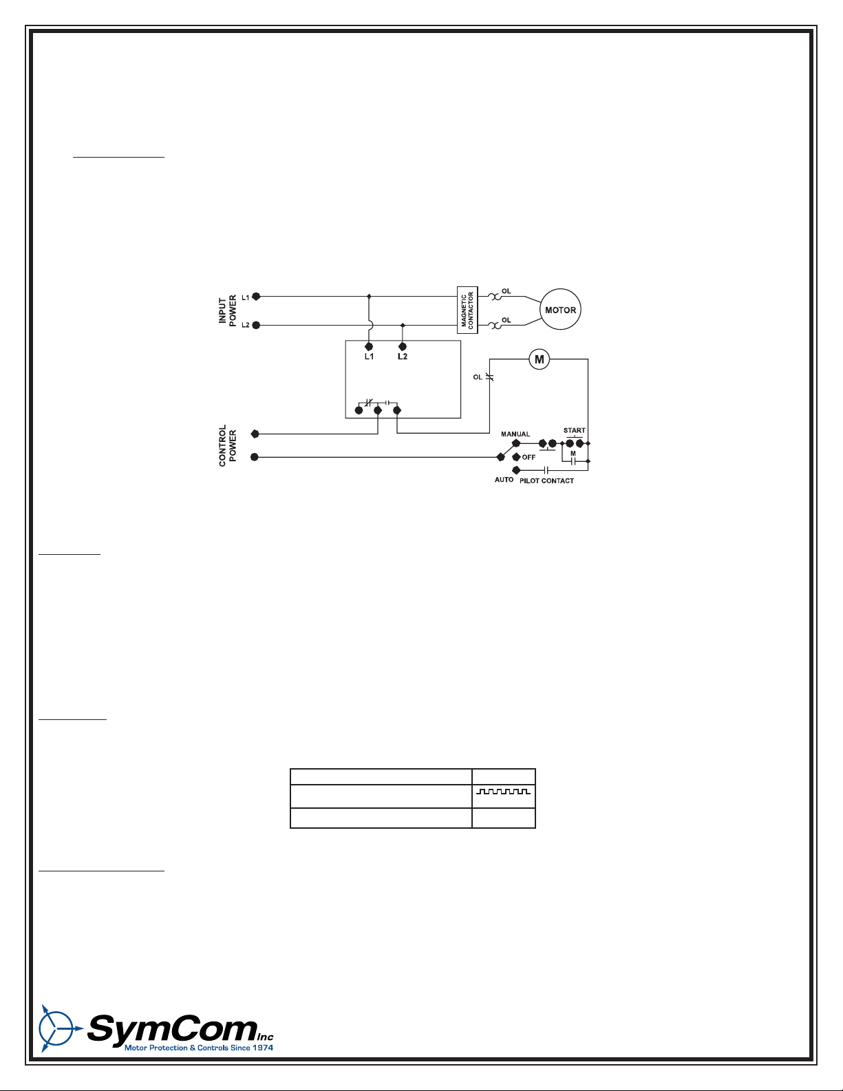
To control a motor: Connect the normally open contact in series with the magnetic coil of the motor starter.
Figure No. 1:Typical Wiring Diagram
CONNECTIONS
1. Mount the MotorSaver in a convenient location in or near the motor control panel. If the location is wet or dusty, then the MotorSaver
should be mounted in a NEMA 4 or 12 enclosure.
2. Connect the lines of the power supply to L1 and L2 on the MotorSaver’s terminal strip (see Figure No. 1).
3. Connect the output relay to the circuitry to be controlled (see Figure No. 1).
For motor control, use the ‘C’ and the ‘NO’ terminals.
For alarm circuits, use the ‘C’ and the ‘NC’ terminals.
RUN
RESTART DELAY
HIGH / LOW VOLTAGE
GREEN
GREEN
RED
INDICATOR LIGHT
DIAGNOSTICS
Page 2

WARRANTY
Seller warrants to the buyer that products furnished will be free from defects in material and workmanship, exclusive of corrosion, for a
period of five years from the date of shipment from its factory, provided said products have been installed, maintained and operated in
conformance with any applicable specifications and recommendations of the Seller. The sellers liability under this warranty shall be limited to
the replacement within the aforesaid time of any defective work or material limited at the Seller’s factory and shall not be liable for any labor
or other repair costs made outside the Seller’s factory without the written consent of the Seller. The Seller shall be liable for no other
damages or losses. The warranty described in this paragraph shall be IN LIEU OF ANY OTHER WARRANTY EXPRESSED OR IMPLIED
INCLUDING BUT NOT LIMITED TO ANY IMPLIED WARRANTY OF MERCHANTABILITY OR FITNESS FOR A PARTICULAR PURPOSE.
0.150" (3.81)
2.163"
(54.94)
2.913"
(73.99)
4.030" (102.36)
5.250" (133.35)
4.500" (114.30)
.375"
(9.53)
2.900"
(73.66)
SymCom, Inc.
RESTART
DELAY
(SECONDS)
70
2
MAN
150
220
300
C
IND. CONT. EQ
LISTED
784X
U
L
®
IND. CONT. EQ
LISTED
784X
U
L
®
GEN. PURPOSE RATING
10 A at 240 VAC
PILOT DUTY RATING
480 VA at 240 VAC
RUN
LIGHT
MODEL 50R
P/N- MS50R - 200
220208
200
190
230
240
LINE VOLTAGE
ADJUST
(VAC)
L1 L2
190-240 VAC, 1Ø, 50/60 HZ
Rapid City, SD
DIMENSIONS FOR MODEL 50R
SIDE
FRONT
 Loading...