

Page 1
460L
INSTALLATION INSTRUCTIONS FOR SYMCOM’S
MOTORSAVER
®
MODEL 460L
BE SURE POWER IS DISCONNECTED PRIOR TO INSTALLATION!!
FOLLOW NATIONAL, STATE AND LOCAL CODES!
CONNECTIONS
1. Mount the MOTORSAVER®in a convenient location in or near the motor control panel. If the
location is wet or dusty, then the MOTORSAVER
®
should be mounted in a NEMA 4 or 12
enclosure. The 460L can be mounted to a back panel using two #6 or #8 x 5/8 screws or can be
snapped on to a DIN rail.
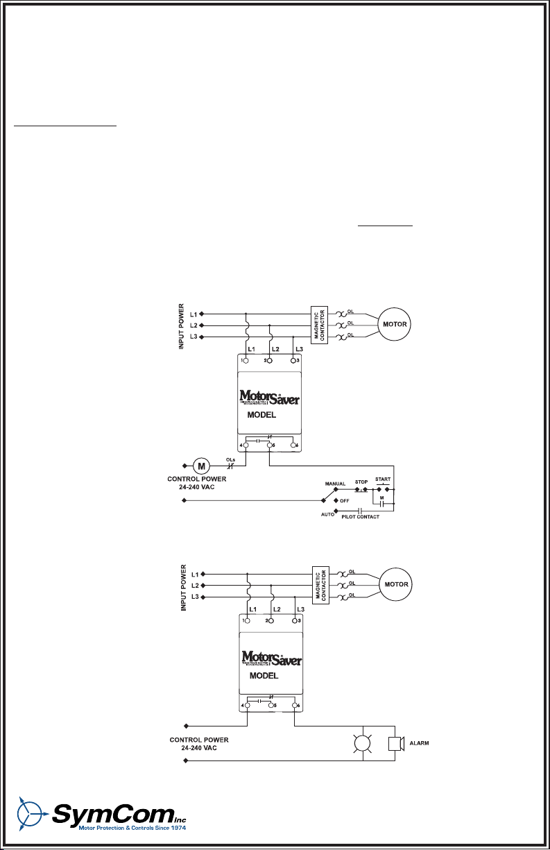
2. Connect L1, L2 and L3 on the MotorSaver’s terminal strip to the LINE SIDE
of the motor starter.
(See Figure No. 1).
3. Connect the output relay to the circuitry to be controlled. Connect the normally open contact in
series with the magnetic coil of the motor starter as shown in Figure No. 1 for motor control.
Connect normally closed contact in control circuit as shown in figure No. 2 for alarm operation.
Figure No. 1: Motor Control Wiring Diagram
LIGHT
460L
Figure No. 2: Alarm Wiring Diagram
2880 North Plaza Drive, Rapid City, SD 57702 • (800) 843-8848
Page 2
SETTINGS
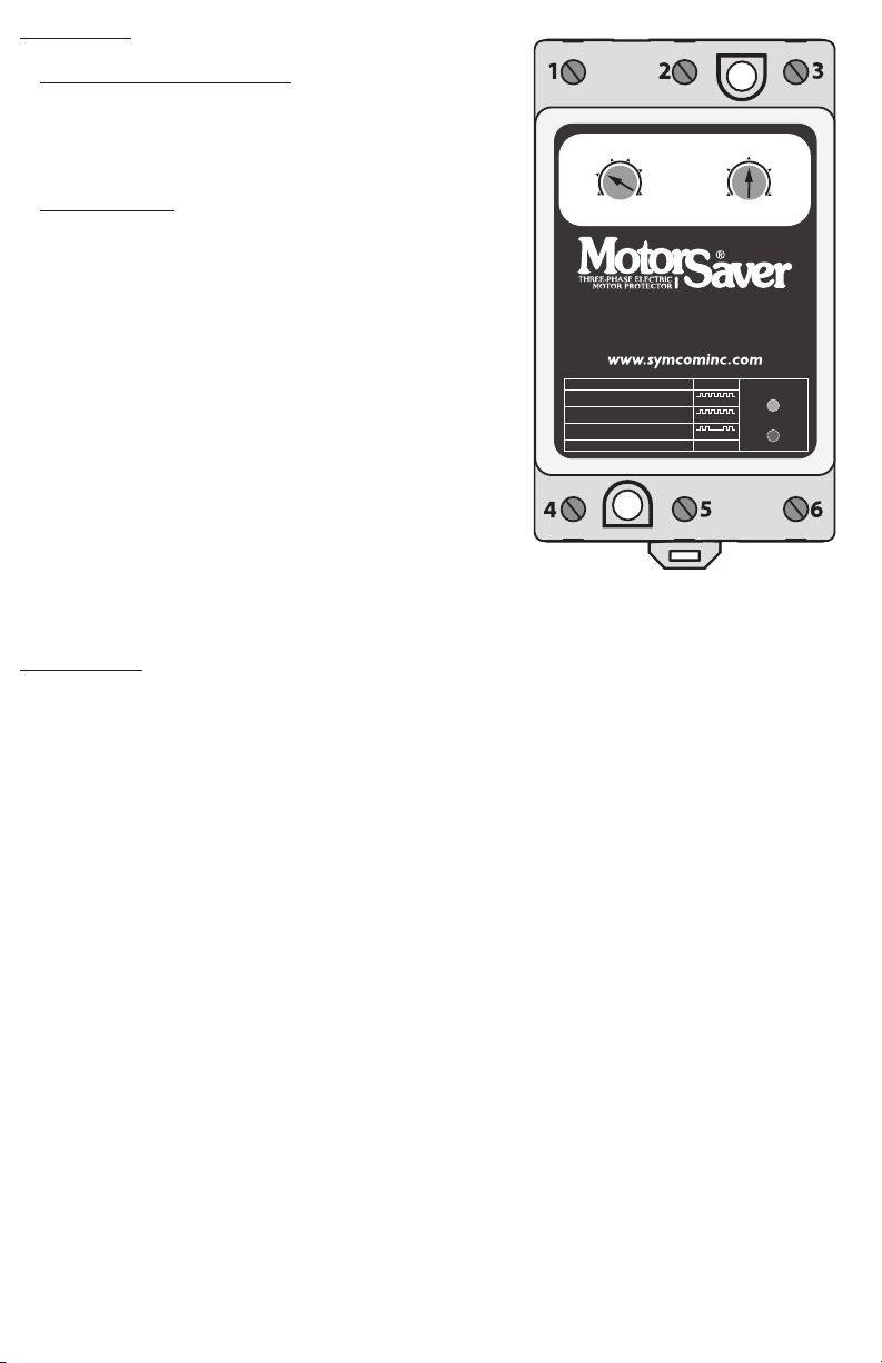
1. LINE VOLTAGE ADJUSTMENT: Rotate the LINE VOLTAGE
ADJUSTMENT to the nominal three-phase line voltage
feeding the motor to be protected. The Model 460L will
automatically sense whether it is connected to a 200V or
400V 60 Hz or 380V - 416V 50Hz power system.
2. RESTART delay: Rotate the RESTART delay to the
desired position. The restart delay is the time between the
MOTORSAVER
®
seeing acceptable power and the
MOTORSAVER
®
closing its output contacts. For compressor
applications, the restart delay should be set for the
approximate time it takes for the head pressure to bleed
off of the compressor. For other applications, the restart
delay is typically set at 2 seconds.
POWER-UP
Turn on the power to the motor. The green RUN LIGHT will blink during the RESTART delay.
After the RESTART delay, the MOTORSAVER
®
will energize its output contacts and the green RUN
LIGHT will light. If the contacts do not energize and the RUN LIGHT does not light, then see the
TROUBLESHOOTING section.
CONGRATULATIONS!!! YOU HAVE JUST INSTALLED
THE FINEST MOTOR PROTECTION AVAILABLE!
HAVE QUESTIONS? CALL 1-800-843-8848
100
5001
VOLTAGE ADJ. (VAC) RESTART (SEC)
MODEL 460L
P/N MS460L
220
440
230
460
20 250
240
480
200
400
190
380
208
416
LED STATUS
RUN
RESTART DELAY
REVERSE PHASE
HIGH / LOW VOLTAGE
UNBALANCE / SINGLE PHASE
GREEN
GREEN
RED
RED
RED
05/03 - 2 -
Page 3

MOTPMYS
THGIL
NRETTAPNRETTAP
NRETTAP
NRETTAPNRETTAP
NOITULOS
tinuehT.noerasthgiloN
.daedyletelpmocsmees
AN
eht,CAV051woleberasegatlovehtfoynafI.segatlovenil-ot-enileerhtehterusaeM
.scinortcelelanretnistietarepootrewophguoneevahtonseodL064ledoM
.metsysdesahp-elgnisanoruccoyamsihT
.8488-348-008-1@moCmySllac,tcerrocerasegatlovehtfI
nogniknilbsithgildeR
.purewopnoitallatsnilaitini
ro2L,1L:L064ledoMehtgnirewopsdaelowtynapawS.rewopesahp-eerhtehtffonruT
nruT.emittsrifehtyltcerrocpu3Ldna2L,1Lgnitcennocfoecnahc05-05aevahuoY.3L
.rewopesahp-eerhtehtno
gniknilbsithgildeR
neebsahrotomehtretfa
.gninnurylsuoiverp
ehtotsenilrewopgnimocniowtynapawS.desahpesreverneebevahsenilgnimocniehT
.rotcatnoccitengam
gniknilbsithgildeR
.nrettapsihtni
ecnalabnu%etaluclacdnasegatlovenilgnimocnierusaeM.ecnalabnuegatlovsetacidnI
ehtnotesecnalabnu%5.4ehtdeecxetonseodecnalabnuegatlovfI.wolebnwohssa
.8488-348-008-1tamoCmySllactnorf
.ydaetsnosithgildeRAN
ehtfI.segatloveerhtehtfoegarevaehtetaluclaC.segatlovenil-ot-enileerhtehterusaeM
neht,TSUJDAEGATLOVENILybtessaegatlovlanimonehtfo%7±foedistuosiegareva
.ylreporpgninoitcnufsiL064ledoMeht
.8488-348-008-1@moCmySllac,wodniwteserehtnihtiwsiegatlovehtfI
tubsknilbthgilneerG
.tratstonseodrotom
.yaledtratsernisiL064ledoMehT
tubydaetsnosithgilneerG
.tratstonseodrotom
AN.sehctiwsgninoitcnuflamroseriwesoolroftiucriclortnockcehC
INDICATOR LIGHT DIAGNOSTICS
TROUBLESHOOTING
- 3 - 05/03
NEMA MG1 UNBALANCE FORMULA
% Voltage Unbalance = [(Maximum Deviation from the Average) / Average] x 100%
Page 4

SymCom warrants its microcontroller based products against defects in material or workmanship for a
period of five (5) years from the date of manufacture. All other products manufactured by SymCom shall
be warranted against defects in material and workmanship for a period of two (2) years from the date of
manufacture. For complete information on warranty, liability, terms, returns, and cancellations, please
refer to the SymCom Terms and Conditions of Sale document.
05/03 - 4 -
Specifications
3-Phase Line Voltage ..................................190 - 480 VAC
......................................................................(475 - 600 VAC Optional)
......................................................................(95 - 120 VAC Optional)
Frequency ..................................................50* or 60 Hz
Low Voltage (% of set point)
•Trip ................................................................90% ±1%
•Reset ............................................................93% ±1%
High Voltage (% of set point)
•Trip ................................................................110% ±1%
•Reset ............................................................107% ±1%
Voltage Unbalance (NEMA)
•Trip ................................................................6%
•Reset ............................................................4.5%
Trip Delay Time
•Low & High Voltage and Unbalance ............4 seconds
•Single Phasing Faults (>25% UB) ................1 second
Restart Delay Time
•After a Fault ..................................................1 - 500 seconds adjustable
•After a Complete Power Loss ......................1 - 500 seconds adjustable
Output Contact Rating
•1-Form C ......................................................10 A General Purpose @240 VAC
......................................................................Pilot Duty 480VA @ 240 VAC, B300
Power Consumption ..................................6 Watts (Max.)
Weight ..........................................................14 oz.
Enclosure ......................................................polycarbonate
Terminal Torque............................................6lbs-in.
Wire Type ......................................................Stranded or solid 12-20 AWG, one per terminal
Safety Marks
•UL..................................................................UL508
•CE ................................................................IEC 60947-6-2
Standards Passed
•Electrostatic Discharge (ESD) ......................IEC 1000-4-2, Level 3, 6kV contact, 8kV air
•Radio Frequency Immunity, Radiated ..........150 MHz, 10V/m
•Fast Transient Burst......................................IEC 1000-4-4, Level 3, 3.5 kV input power & controls
Surge
•IEC ................................................................IEC 1000-4-5, Level 3, 4kV line-to-line;
......................................................................Level 4, 4kV line-to-ground
•ANSI/IEEE ....................................................C62.41 Surge and Ring Wave Compliance
......................................................................to a level of 6kV line-to-line
•Hi-potential Test ............................................Meets UL508 (2 x rated V +1000V for 1 minute)
Environmental
Temperature Range........................................Ambient Operating: -20° - 70° C (-4° - 158°F)
......................................................................Ambient Storage: -40° - 80° C (-40° - 176°F)
Class of Protection ........................................IP20, NEMA 1 (FINGER SAFE)
Relative Humidity ..........................................10-95%, non-condensing per IEC 68-2-3
*Note: 50 Hz will increase all delay timers by 20%
 Loading...