

Page 1
202 SERIES
3-Phase Voltage/Phase Monitor
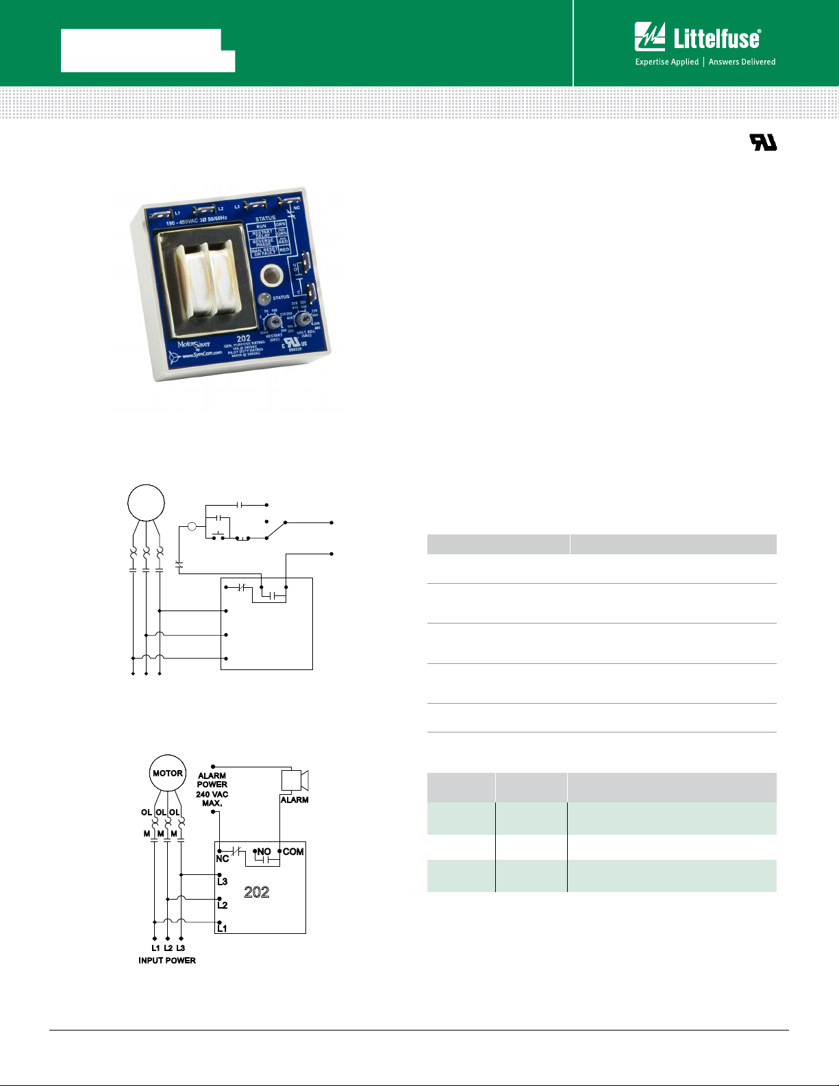
Wiring Diagram
202 WITH MOTOR CONTROL
MOTOR
OL OL OL
M M M
L1
L3
L2
INPUT POWER
MOTOR
OL OL OL
M M M
L1
L2
INPUT POWER
M
M
START
OL
202 WITH ALARM CIRCUIT
ALARM
POWER
240 VAC
MAX.
NC
L3
AUTO
OFF
HAND
STOP
NC
NO COM
L3
202
L2
L1
ALARM
NO COM
L3
202
L2
L1
CONTROL
VOLTAGE
240 VAC MAX.
Description
The 202 Series is a 3-phase, auto-ranging, dual-range voltage
monitor that protects 190-480VAC, 50*/60Hz motors regardless
of size. The 202-RP (and the 202-575-RP for 475-600VAC)
monitors the phase rotation of 3-phase systems and trips on
reverse-phase only. Critical applications include fan motors,
scroll compressors, grinders, conveyor systems, elevators and
escalators. Both products provide a user selectable nominal
voltage setpoint and automatically select between the 200V and
400V range.
This unique microcontroller-based voltage and phase-sensing
device constantly monitors the 3-phase voltages to detect
harmful power line conditions. When a harmful condition is
detected, the MotorSaver’s output relay is deactivated after a
specified trip delay. The output relay reactivates after power line
conditions return to acceptable levels for a specified amount of
restart delay time (or a manual reset). The 202 Series includes
advanced single LED diagnostics. Five different light patterns
distinguish between faults and normal conditions. The status
light turns green and the relay is activated when rotation is
correct.
Features & Benefits
FEATURES BENEFITS
Compact, quick
mounting design
Proprietary
microcontroller
based circuitry
Auto-sensing wide
voltage range
(202 & 202-RP
Advanced LED
diagnostics
Adjustable trip
delay (202)
1-screw mounting saves time and space. Small
footprint ideal for assembly into panels.
Constant monitoring of single-phase, low voltage,
high voltage, voltage unbalance, phase reversal,
harmful power line conditions.
Automatically senses system voltage between
90 - 480VAC. Saves setup time.
Quick visual indicator for cause of trip. LED
indications include: normal operation, restart delay,
reverse-phase trip, fault
Prevent nuisance tripping due to rapidly fluctuating
power line conditions.
Ordering Information
MODEL
202
202-RP
202-575-RP
LINE
VOLTAGE
190 -4 80 VAC
190 -4 80 VAC
475-600 VAC
DESCRIPTION
Standard protection with low/high voltage
trip, voltage unbalance
Trips on reverse-phase only
Designed for higher voltage systems and
trips on reverse-phase only
Rev: 1-A-062116
Page 2

202 SERIES
Specifications
Frequency 50*/ 60Hz
Functional Characteristics
Phase Sequence ABC
Low Voltage (% of setpoint)
Trip 90%
Reset 93%
High Voltage (% of setpoint)
Trip 110%
Reset 107%
Voltage Unbalance (NEMA)
Trip 6%
Reset 4.5%
Trip Delay Time
High and Low Voltage 4 seconds
Unbalance & Phasing Faults 2 seconds
Restart Delay Time
After a Fault Manual, 2-300 seconds adj.
After a Complete Power Loss Manual, 2-300 seconds adj.
Output Characteristics
Output Contact Rating (SPDT)
Pilot Duty 48 0VA @ 240 VAC
General Purpose 10A @ 240VAC
General Characteristics
Temperature Range -40° to 70°C (-40° to 158°F)
Trip & Reset Accuracy ±1%
Repeatability ±0.5%
Maximum Input Power 5 W
Relative Humidity 95%, non-condensing
Transient Protection IEC 61000-4-5, ±4kV
Hi-potential Test Meets UL508
(2x rated V+1000V for 1 minute)
Termination 0.25” male quick connect
Safety Marks
UL Recognized UL508 (File #E68520)
Dimensions H 63.5 mm (2.5”); W 63.5 mm (2.5”);
D 35.56 mm (1.4”)
Weight 0.5 lb. (8 oz., 226.8 g)
Mounting Method 1/4” socket head cap screw
(customer supplied)
*Note: 50Hz will increase all delay timers by 2 0%. CE Pending
Rev: 1-A-062116
 Loading...