

Page 1
2880 North Plaza Drive, Rapid City, SD 57702 • (800) 843-8848
INSTALLATION INSTRUCTIONS FOR SYMCOM’S
MOTORSAVER MODEL 202
BE SURE POWER IS DISCONNECTED PRIOR TO INSTALLATION!!
FOLLOW NATIONAL, STATE AND LOCAL CODES!
CONNECTIONS
1. Mount the MotorSaver in a convenient location in or near the motor control panel using a 1/4” socket head cap screw (customer supplied).
If the location is wet or dusty, then the MotorSaver should be mounted in a NEMA 4 or 12 enclosure.
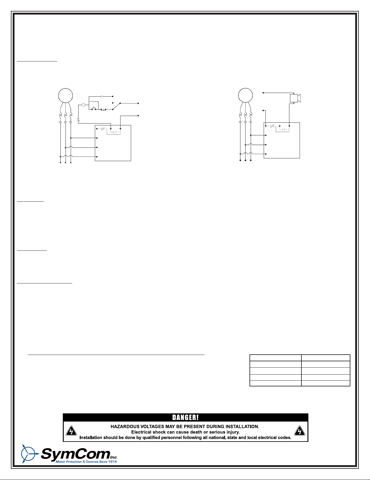
2. Connect the three lines of the motor’s three-phase power supply to L1, L2 and L3 using insulated 1/4” female, UL recognized quick connectors. (see Figure No. 1).
3. Connect the output relay to the circuitry to be controlled using insulated 1/4” female, UL recognized quick connectors. (see Figure No. 1).
SETTINGS
1. LINE VOLTAGE ADJUSTMENT: Rotate the LINE VOLTAGE ADJUSTMENT to the nominal three-phase line voltage feeding the motor to be protected.
2. TIME DELAY RESTART: Rotate the RESTART DELAY to the desired position. The restart delay is the time between the MotorSaver seeing
acceptable power and the MotorSaver closing its output contacts. For compressor applications, the restart delay should be set for the approximate
time it takes for the head pressure to bleed off of the compressor. For other applications, the restart delay is typically set at 2 seconds. If the
RESTART DELAY is in the MAN (manual) position, then the unit will not automatically restart until it is turned out of the MAN position.
Setting multiple units at staggered restart delays will enable sequential starting on a complete power loss.
POWER-UP
Turn on the power to the motor. During the restart delay the STATUS LIGHT will flash green. After the RESTART DELAY, the MotorSaver will energize its
output contacts and the STATUS LIGHT will turn solid green. If the contacts do not energize and the STATUS LIGHT does not turn solid green, then see
the TROUBLESHOOTING section.
Congratulations!!! You have just installed the finest motor protection available!
TROUBLESHOOTING
If the output relay does not energize and the STATUS LIGHT does not turn solid green after waiting for the RESTART DELAY time, then:
1. If the STATUS LIGHT turns solid red, upon applying power, the 202 may be in the manual reset mode. Rotate the Restart Delay Adjustment clockwise
1/8 turn, above "2." You may be pointed at "Manual" or close enough to the Manual reset position that the unit will not automatically restart. If the
light does not flash green, proceed to step 2.
2. If the STATUS LIGHT flashes red, turn off the three-phase power. Swap any two leads: L1-L2 or L2-L3 or L3-L1. You have a 50-50 chance of
connecting L1, L2 and L3 up correctly the first time. Turn on the three-phase power.
3. If the MotorSaver still seems to be malfunctioning and the STATUS LIGHT is solid red, measure the three line-to-line voltages. Calculate the
average of the voltages. If the average voltage is 7% above or 7% below the voltage adjust set point, the MotorSaver is functioning properly, saving
your motor from abnormal power conditions.
4. If the average of the three line voltages is within ±7%,
calculate the voltage unbalance using the NEMA method shown below:
% voltage unbalance = (max. deviation / Average of the three voltages) x 100
EXAMPLE:
Find the largest deviation from the average voltage and divide it by the average for the NEMA unbalance.
L1 - L2 = 460VAC, L2 - L3 = 466 VAC, L3 - L1 = 490 VAC
Average = (460 + 466 + 490)/3 = 472
490 is the largest deviation from the average voltage.
Max. deviation = 490 - 472 = 18
% voltage unbalance = (18/472) x 100 = 3.8%
If the percent voltage unbalance is greater than 4.5% , then MotorSaver is functioning properly, saving your motor from abnormal power conditions.
5. If the percent voltage unbalance is less than 4.5%, then contact SymCom at 1-800-843-8848 OR 1-605-348-5580 and we will be happy to help you.
L1
L1
MOTOR
START
HAND
OFF
AUTO
CONTROL
VOLTAGE
240 VAC MAX.
STOP
INPUT POWER
L2
L2
L3
L3
NC
NO COM
MS202
OL OL OL
OL
MMM
M
M
L1
L1
MOTOR
ALARM
ALARM
POWER
240 VAC
MAX.
INPUT POWER
L2
L2
L3
L3
NC
NO COM
MS202
OL OL OL
MMM
(A) To control a motor: Connect the normally open contact in series
with the magnetic coil of the motor starter as shown.
(B) To sound an alarm: Connect the normally closed contact in series
with the alarm as shown.
Figure No. 1:Typical Wiring Diagram
CONDITION
Run
Restart Delay
Reverse Phase
Manual Reset or Fault
LIGHT OPERATION
Solid Green
Flashing Green
Flashing Red
Solid Red
STATUS LIGHT
Page 2
WARRANTY
Seller warrants to the buyer that products furnished will be free from defects in material and workmanship, exclusive of corrosion, for a
period of five years from the date of shipment from its factory, provided said products have been installed, maintained and operated in
conformance with any applicable specifications and recommendations of the Seller. The Seller’s liability under this warranty shall be limited
to the replacement within the aforesaid time of any defective work or material limited at the Seller’s factory and shall not be liable for any labor
or other repair costs made outside the Seller’s factory without the written consent of the Seller. The Seller shall be liable for no other
damages or losses. The warranty described in this paragraph shall be IN LIEU OF ANY OTHER WARRANTY EXPRESSED OR IMPLIED
INCLUDING BUT NOT LIMITED TO ANY IMPLIED WARRANTY OF MERCHANTABILITY OR FITNESS FOR A PARTICULAR PURPOSE.
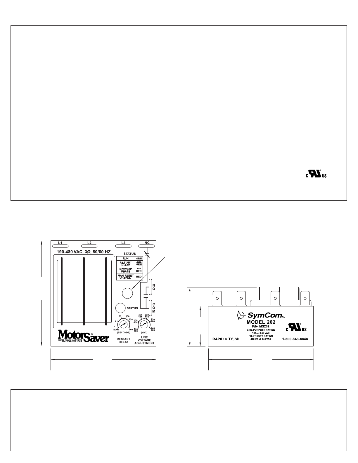
.25" Mounting Hole
2.5"
1.4"
.95"
2.5"
2.5"
3-Phase Line Voltage ......................190 to 480 VAC ± 10%
Frequency ........................................*50 or 60 Hz
Phase Sequence ..............................ABC
Nominal Voltage Set Points ............190, 200, 208, 220, 230, 240
............................................................380, 400, 416, 440, 460, 480
Low Voltage (% of set point)
•Trip ....................................................90%
•Reset ................................................93%
High Voltage (% of set point)
•Trip ....................................................110%
•Reset ................................................107%
Voltage Unbalance (NEMA)
•Trip ....................................................6%
•Reset ................................................4.5%
Trip Delay Time
•High and Low Voltage........................4 seconds
•Unbalance & Phasing Faults ............2 seconds
*Note: 50 Hz will increase all delay timers by 20%.
Restart Delay Time
•After a fault or complete power loss..MAN, 2-300 seconds adjustable
Output Contact Rating
•SPDT ................................................480 VA @ 240 VAC Pilot Duty
............................................................or 10A @240
VAC Gen. Purpose
Transient Protection ........................IEC 1000-4-5, ±4kV
Power Consumption ........................5 Watts (Max.)
Weight ..............................................8 oz.
Trip & Reset Accuracy......................± 1%
Repeatability......................................± 0.5%
Input to Output Dielectric ................1960 Vrms min.
Termination........................................0.25" Male Quick Connect
Humidity ............................................95% Relative Non Condensing
Operating Temperature ....................-40 to +70˚ C
CE Pending
UL Recognized
..................................File # E68520
DIMENSIONS FOR MODEL 202
Specifications
 Loading...