

Page 1
INSTALLATION
INSTRUCTIONS
Rapid City, SD, USA, 04/2010
MODELS 201-100-SP
201-200-SP
201-200-SP-T-9
Revision B1
II_201-SP_B1
2880 North Plaza Drive, Rapid City, South Dakota 57702
(800) 843-8848 · (605) 348-5580 · fax (605) 348-5685
Page 2

BE SURE POWER IS DISCONNECTED PRIOR TO INSTALLATION!
FOLLOW NATIONAL, STATE AND LOCAL CODES.
SymCom’s MotorSaver
READ THESE INSTRUCTIONS ENTIRELY BEFORE INSTALLATION.
®
Models 201-XXX-SP and 201-200-SP-T-9 are voltage monitors designed to
protect single-phase motors regardless of size. They can be used on 95-120VAC (201-100-SP) or
190-240VAC (201-200-SP and 201-200-SP-T-9) motors to prevent damage caused by low voltage.
High voltage detection is included only on the 201-200-SP-T-9 model.
CONNECTIONS
1. Locate a convenient location in or near the motor control panel. If the location is wet or
dusty, the MotorSaver
®
should be mounted in a NEMA 4 or 12 enclosure.
2. Mount an 8-pin socket to the motor control back panel (SymCom P/N OT08-PC, sold
separately, is required for UL rating).
3. Connect L1 and L2 (terminals 3 and 4 for Model 201-XXX-SP and terminals 6 and 7 for
Model 201-200-SP-T-9) to the LINE SIDE of the motor starter as shown in Figures 1 and 2.
4. Connect the output relay to the circuitry to be controlled. For motor control, connect the
normally open contact in series with the magnetic coil of the motor starter as shown in
Figures 1 and 2. For alarm operation, connect the normally closed contact in series with the
control circuit (terminals 1 and 2).
5. Plug the MotorSaver
®
into the socket.
© 2010 SymCom, Inc. All Rights Reserved 2
Page 3
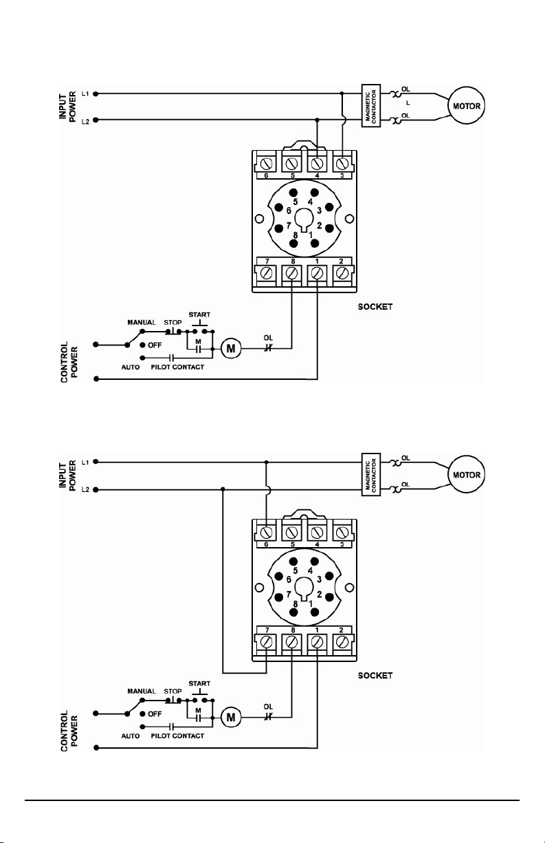
Figure 1: Typical Wiring Diagram for 201-100-SP, 201-200-SP
Figure 2: Typical Wiring Diagram for 201-200-SP-T-9
© 2010 SymCom, Inc. All Rights Reserved 3
Page 4

Figure 3: Pin-Out for 201-100-SP
and 201-200-SP
Figure 4: Pin-Out for 201-200-SP-T-9
SETTINGS
Rotate the LINE VOLTAGE ADJUSTMENT knob to the nominal line voltage feeding the motor to be
protected.
Figure 5: Adjustable Settings
OPERATION
After applying power to the MotorSaver®, the green RUN light will blink during the restart delay. After
the restart delay time has expired, the MotorSaver
normally closed and close the normally open contacts) and the RUN light will turn solid green.
If the contacts do not energize and the RUN light does not turn solid green, see the
TROUBLESHOOTING section.
®
will energize its output contacts (open the
INDICATOR LIGHT STATUS
GREEN RUN
GREEN
RED LOW VOLTAGE
RED
RESTART DELAY
HIGH VOLTAGE (201-200-SP-T-9 ONLY)
Table 1: Diagnostic Indicator Lights
© 2010 SymCom, Inc. All Rights Reserved 4
Page 5

TROUBLESHOOTING
SYMPTOM
No lights are on -
the unit seems
completely dead
Red light is blinking
in this pattern
(201-200-SP-T-9
ONLY)
Red light is on
steady
Green light blinks
and motor is not
running
Green light is on
steady, but motor
does not start
LIGHT
PATTERN
N/A
RED
RED
GREEN
GREEN
SOLUTION
Verify input power is connected to terminals as shown
in Figures 1 and 2. If the voltage is below the specified
operating voltage, the MotorSaver
®
does not have
enough power to operate its internal electronics. If the
voltage is correct, call SymCom at (800) 843-8848 or
(605) 348-5580.
The voltage is high. If the voltage is 7% above the line
voltage adjustment setting, the MotorSaver
functioning properly. If the voltage is within 7%, call
®
is
SymCom at (800) 843-8848 or (605) 348-5580.
The voltage is low. If the voltage is 7% below the line
voltage adjustment setting, the MotorSaver® is
functioning properly. If the voltage is within 7%, call
SymCom at (800) 843-8848 or (605) 348-5580.
®
The MotorSaver
and will energize its contacts when finished
is timing through the restart delay
The MotorSaver® is in run mode. Ensure other control
devices are allowing the motor to start. Check control
circuit for loose wires or malfunctioning switches.
© 2010 SymCom, Inc. All Rights Reserved 5
Page 6
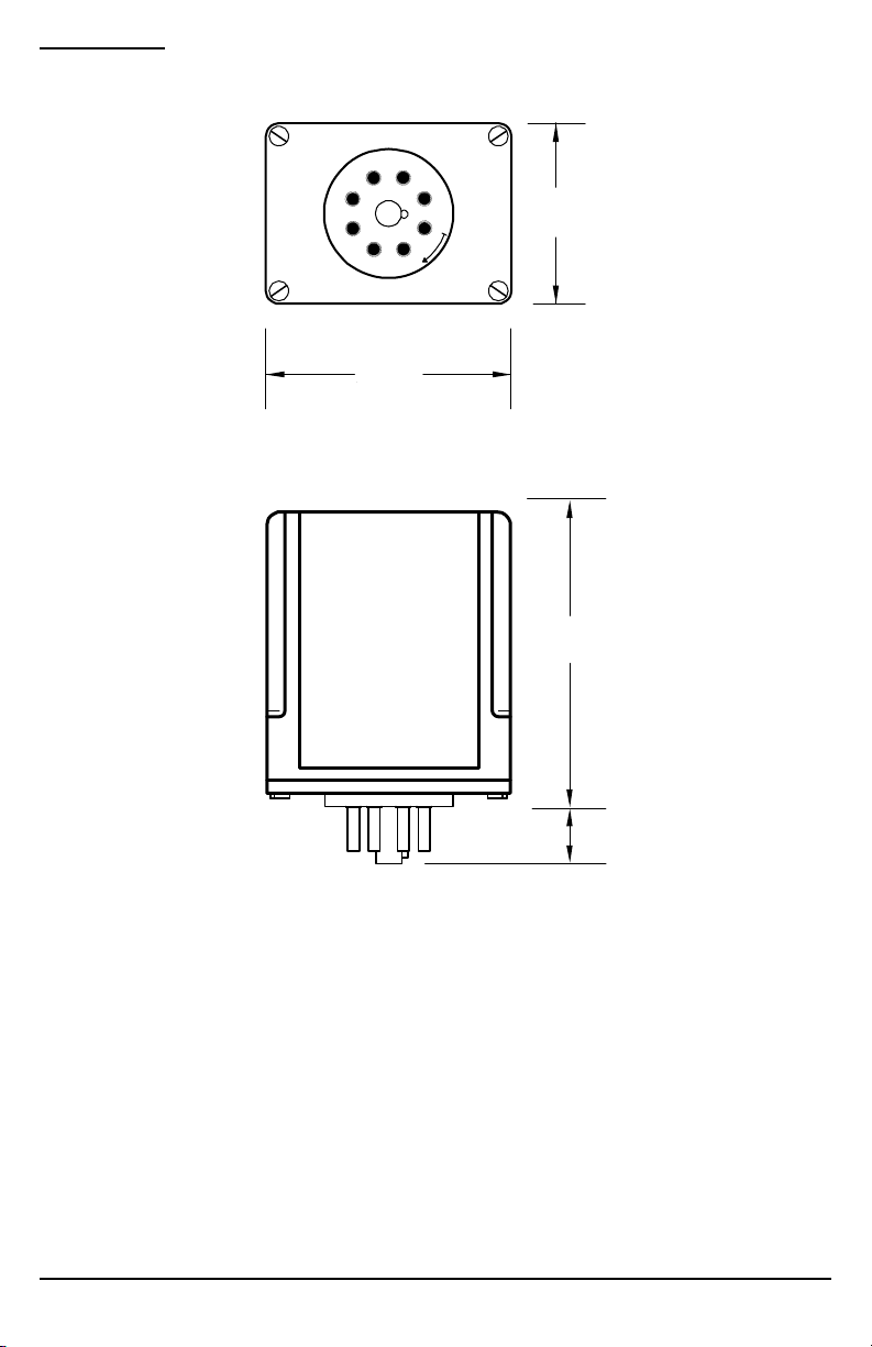
DIMENSIONS
S
NOTE: Use of the OT08-PC or RB08-PC octal socket, manufactured by Custom Connector Corp., is
required for the MotorSaver to qualify as a UL Listed device. The OT08-PC is 35mm DIN rail
compatible.
2.375
(60.331)
BOTTOM
IDE
.5
(12.7)
1.75
(44.55)
3.15
(80.01)
© 2010 SymCom, Inc. All Rights Reserved 6
Page 7
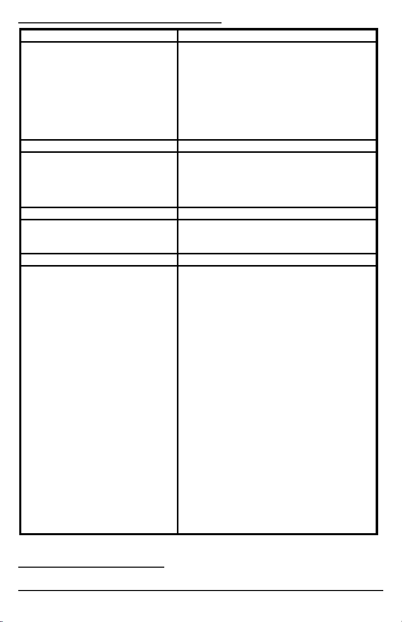
MOTORSAVER® 201-XXX-SP SPECIFICATIONS
Functional Characteristics
Low Voltage Trip 90% of setting Reset 93% of setting High Voltage (201-200-SP-T-9 ONLY) Trip 110% of setting Reset 107% of setting Trip Delay High/Low Voltage 4 seconds Restart Delay 2 seconds
Input Characteristics Line Supply Voltage
201-100-SP 95-120VAC 201-200-SP 190-240VAC 201-200-SP-T-9 190-240VAC Frequency 50/60Hz
Output Characteristics Output Contact Rating
Pilot Duty 480VA @ 240VAC General Purpose 10A @ 240VAC
General Characteristics Environmental
Ambient Operating Temperature Relative Humidity 10-95%, non-condensing per IEC 68-2-3 Maximum Input Power 5 W Standards Passed Electrostatic Discharge (ESD) IEC 61000-4-2, Level 3, 6kV contact, 8kV air Radio Frequency Immunity, Radiated 150 MHz, 10V/m Fast Transient Burst IEC 61000-4-4, Level 4, 4kV input power and controls Surge Immunity IEC IEC 61000-4-5, Level 4, 4kV line-to-line; Level 4, 4kV
ANSI/IEEE C62.41 Surge and Ring Wave Compliance to a level
Hi-Potential Test Meets UL508 Safety Marks
UL listed (OT08 octal socket
required) CE IEC 60947-6-2 Dimensions 1.750” H x 2.375” W x 4.125” D (with socket) Weight 9 oz. Enclosure Polycarbonate Mounting Method Plugs into OT08 Socket Wire Gauge 12-22 AWG Solid or Stranded Terminal Torque for P/N OT08 Socket 12 in. - lb
1
-40° to 70°C (-40° to 158°F)
line-to-ground
of 6kV line-to-line
(2 x rated V +1000 V for 1 minute)
UL508 (File #E68520)
1
The ambient air temperature is the air temperature directly surrounding the product.
© 2010 SymCom, Inc. All Rights Reserved 7
Page 8

For warranty information, please see Terms and Conditions at
www.symcom.com
Visit us at www.symcom.com to see
our complete product listing!
Need something special?
Contact SymCom today
for your custom solution!
800-843-8848
© 2010 SymCom, Inc. All Rights Reserved 8
 Loading...