

INSTALLATION INSTRUCTIONS
FOR SYMCOM’S MOTORSAVER
MODEL 102600
The Model 102600 is a three-phase voltage monitor designed to protect 600
VAC motors regardless of horsepower. It will protect 50 to 60 Hz motors from
damage caused by single phasing, phase reversal, voltage unbalance, and low
voltage.
CONNECTIONS
1.Mount the MotorSaver® in a convenient location in or near the motor
control panel. If the location is wet or dusty, the MotorSaver® should be
mounted in a NEMA 4 or 12 enclosure.
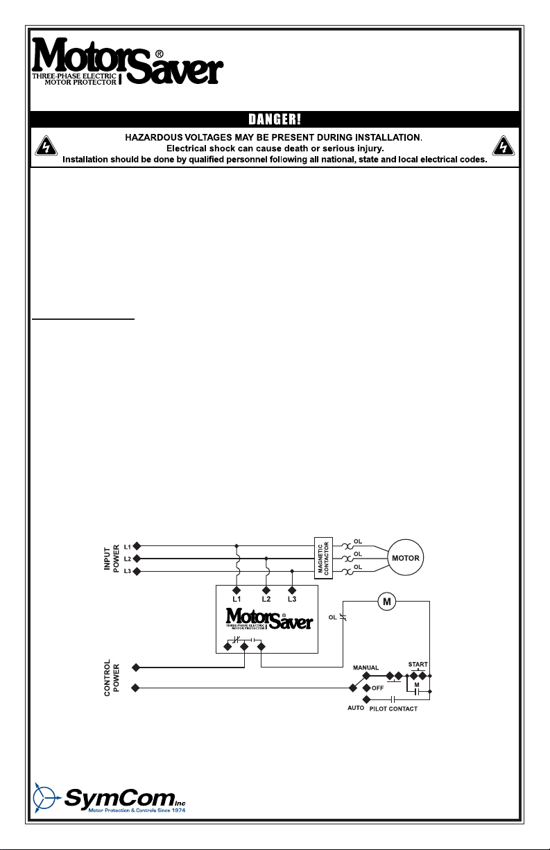
2.Connect the three lines of the motor’s three-phase power supply to L1, L2,
and L3 on the MotorSaver® (see Figure No. 1).
3.Connect the output relay to the circuitry to be controlled (see Figure No. 1
and Figure No. 2).
A. To control a motor, connect the normally open contact in series with the
magnetic coil of the motor starter as shown in Figure 1.
B. To sound an alarm, connect the normally closed contact in series with the
alarm as shown in Figure 2.
Figure No.1: Typical Motor Control Wiring Diagram
2880 North Plaza Drive, Rapid City, SD 57702 • (800) 843-8848
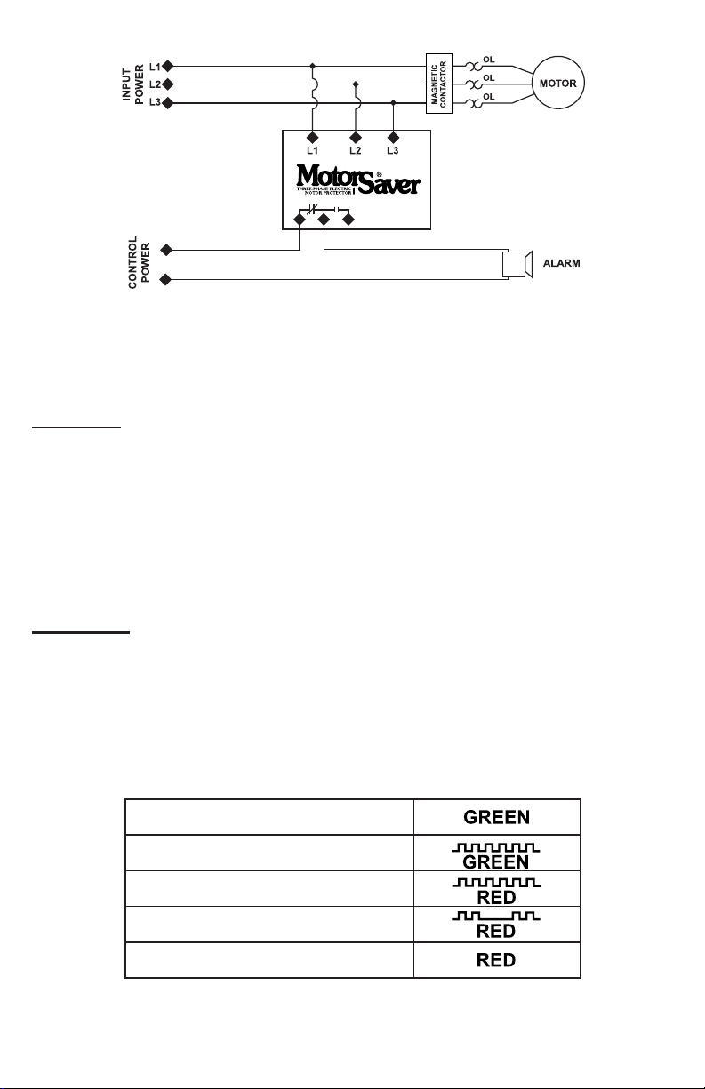
Figure 2: Typical Alarm Wiring Diagram
SETTINGS
1.LINE VOLTAGE ADJUSTMENT: Rotate the LINE VOLTAGE ADJUSTMENT to
the nominal three-phase line voltage feeding the motor.
POWER-UP
Turn on the power to the motor. The MotorSaver® then goes through its restart
delay and the LED will flash green (see Table 1). After the restart delay, the
MotorSaver® will energize its output contacts and the RUN LIGHT will turn solid
green. If the contacts do not energize and the RUN LIGHT does not turn solid
green, then see the TROUBLESHOOTING section.
RUN
RESTART DELAY
REVERSE PHASE
UNBALANCE / SINGLE PHASE
HIGH / LOW VOLTAGE
Table 1: Diagnostic Indicator Lights
07/09/03 -2-

TROUBLESHOOTING
SYMPTOM
No lights are on. The unit
seems completely dead
Red light is blinking
(On initial installation
power up).
Red light is blinking
(After the motor has been
previously running).
Red light is blinking in this
pattern.
Red light is on steady.
Green light blinks, but
motor is not running.
Green light is on steady,
but motor does not start.
LIGHT
PATTERN SOLUTION
Measure the three line-to-line voltages. If any of
the voltages are below 150 VAC, the MotorSaver
N/A
does not have enough power to operate its internal
electronics. This may occur on a single-phased
system. If the voltages are correct, call SymCom at
1-800-843-8848 or 1-605-348-5580.
Turn off the three-phase power. Swap any two
leads powering the MotorSaver (L1, L2, or L3).
There is a 50-50 chance of connecting L1, L2, and
L3 correctly the rst time. Re-apply the three-phase
power.
The incoming lines have been reverse phased. The
MotorSaver is preventing the motor from running
backwards. Correct the phase sequence.
The voltage is unbalanced or single-phased.
Measure the incoming line voltages and calculate
the % unbalance. If the voltage unbalance does not
exceed the % unbalance reset value, call SymCom
at 1-800-843-8848 or 1-605-348-5580.
The voltage is out of tolerance. Measure the three
line-to-line voltages. Calculate the average of
the three voltages. If the average is 7% above or
below the nominal voltage as selected by the LINE
VOLTAGE ADJUST, the MotorSaver is functioning
properly. If the voltage is within ±7% of the selected
line voltage, call SymCom at 1-800-843-8848 or
1-605-348-5580.
The MotorSaver is in restart delay.
The MotorSaver is in run mode. Ensure other control devices are allowing the motor to start. Check
control circuit for loose wires or
malfunctioning switches.
SymCom warrants its microcontroller based products against defects in material or workmanship
for a period of ve (5) years* from the date of manufacture. All other products manufactured by
SymCom shall be warranted against defects in material and workmanship for a period of two (2)
years from the date of manufacture. For complete information on warranty, liability, terms, and
conditions, please refer to the SymCom Terms and Conditions of Sale document.
* The 520 Series has a one (1) year warranty and the LSRU series has a two (2) year warranty.
-3- 07/09/03

SPECIFICATIONS
3-Phase Line Voltage 475 to 600 VAC
Frequency 50 or 60 Hz
Note: 50 Hz will increase all delay timers by 20%
Low Voltage (% of setpoint)
Trip 90%
Reset 93%
Voltage Unbalance (NEMA)
Trip 6%
Reset 4.5%
Trip Delay Time
Low Voltage Faults 4 Seconds
Unbalance / Phasing Faults 2 Seconds
Restart Delay Time
After a fault or complete power loss 2 Seconds
Output Contact Rating - SPDT
Pilot Duty
General Purpose
Transient Protection IEC 1000-4-5 ; 1995 ± 6 kv
Power Consumption 5 Watts (maximum)
Weight 14 Ounces
Terminal
Wire AWG 12-22 Gauge
Maximum Torque 7 inch-pounds
Operating Temperature -40o to +70o C
UL E68520
480 VA @ 240 VAC
10 A @ 240 VAC
Visit our website at www.symcominc.com for our
complete catalog and new product listings!
2880 North Plaza Drive, Rapid City, SD 57702
Phone:(800) 843-8848 or (605) 348-5580
FAX: (605) 348-5685
 Loading...