

Page 1
(1) (2)
(1) (2)
to persons or property.
shall in no way exceed the purchase price of said Product or the f air market value of said service, except in instances of injury
or service. Seller’s liability for damages to Buyer or others re sulting from the use of any Product or service furnished here under
limited to, special, indirect or conseque ntial damages arising out of or in connection wit h the use or performance of the Product
The stated express warranties are in l ieu of all obligations or liabilities on the part of Seller for damages, includin g but not
THIS LIMITED WARRANTY MAY NOT APPLY.
CONSUMER PRODUCTS. IN SUCH STATES OR COUNTRIES, FOR SUCH PRODUCTS, SOME EXCLUSIONS OR LIMITATIONS OF
IMPLIED WARRANTY LASTS OR THE EXCLUSION OR LIMITATION OF INCIDENTAL OR CONSEQUENTIAL DAMAGES FOR
TO THE LIMITED WARRANTY PERIOD. SOME STATES OR COUNTRIES DO NOT ALLOW A LIMITATION ON HOW LONG AN
FITNESS FOR A PARTICULAR USE. ANY IMPLIED WARRANTIES THAT MAY BE IMPOSED BY LAW ARE LIMITED IN DURATION
WARRANTIES ON PRODUCTS FURNISHED HEREUNDER INCLUDING ALL IMPLIED WARRANTIES OF MERCHANTABILITY AND
EXCEPT FOR THE WARRANTY OF TITLE AND THE EXPRESS WARRANTIES STATED ABOVE, SELLER DISCLAIMS ALL
as batteries, supplied with the Product.
applicable Product specification; nor shall the above warranty provisions apply to any expendable or consumable items, such
forces or exposure beyond normal use within the specified operational and environmental parameters set forth in the
instructions supplied by Seller; (iii) which has been subjected to unusua l physical or electrical stress, abuse, or accident, or
or accessories not approved or supplied by Sym bol, or failure to perform operator handling and scheduled maintenance
result from normal wear and tear, misuse, negligence, improper sto rage, water or other liquids, battery leakage, use of parts
with, altered or modified, except by Seller’s authorized service personnel; (i i) in which the defects or damage to the Product
(F) Warranty Provisions The above warranty provisions shall not apply to any Product (i) which has been repaired, tampered
had either been repaired or replaced by Seller.
as provided in Section C above, the aforementio ned provisions do not extend the original warranty period of any Product tha t
(E) Original Warranty Period Except for the warranty applying solely to the r epaired component arising from a repair service
if any, installed by Seller during manufacture of the Product.
removable data storage media, or the restoration or reinstallati on of any software programs or data other than the software,
replacement parts for warranty repairs. Selle r is not responsible for any damage to or loss of any software programs, data or
or for product returned that Seller determines is not eligible for warranty repair. No charge will be made to Buyer for
responsible for return shipment charges for product returned where Seller determines th ere is no defect (“No Defect Found”),
and risks associated with this transportation; return shipment to the Customer will be at Seller's expense. Customer shall be
to service depot” basis with prior Seller autho rization. Customer is responsible for shipment to the Sell er and assumes all costs
The sole obligation of Seller for defective har dware Products is limited to repair or replacement (at Seller’s option) on a “return
returned products and that have bee n tested as meeting applicable specifications for equivalent new mater ial and Products.
(D) Product Service Products may be serviced or manufactured with parts, co mponents, or subassemblies that originate from
Product, or until the end of the original warranty period, whichever is longer.
materials on the repaired comp onent of the Product for a period of thirty (30) days from the shipme nt date of the repaired
including repairs covered by warranty, the repair services provi ded are warranted against defects in workmanship and
(C) Repair of Symbol-branded hardware For repairs on Symbol-branded hardwa re Products under this Agreement,
shipment. Spare parts may be new or origina te from returned units under the conditions set forth in subsection D below.
of Products) are warranted aga inst defects in workmanship and materials for a period of thirty (30) days from the date of
(B) Spare Parts Spare parts (i.e. parts, components, or suba ssemblies sold by Seller for use in the service and maintenance
specification in effect at the time of purchase o r in the accompanying software license.
Products”), remanufactured products, and recondition ed or upgraded products, shall be as provided in the applicable Product
software, integrated installed systems, Produ ct modified or designed to meet specific customer specifications (“Custom
the Product remains unmodified and is op erated under normal and proper conditions. Warranty provisions and duration s on
materials for a period of twelve (12) months from the da te of shipment, unless otherwise provided by Seller in writing, provided
(A) Warranty Symbol Technologies (hereafter “Seller”) hardware Products are warranted against defects in workmanship and
Warranty
European Patent 367,299; 414,281; 367,300; 367,298; UK 2,072,832; France 81/03938; Italy 1,138,713rev. 07/04
Invention No. 55,358; 62,539; 69,060; 69,187 (Taiwan); No. 1,601,796; 1,907,875; 1,955,269 (Japan);
6,011873; 6,080,001; 6,234,389; 6,193,152B1;
D414,171; D414,172; D418,500; D419,548; D423,468; D424,035; D430,158; D430,159; D431,562; D436,104; 5,912,662;
D341,584; D344,501; D359,483; D362,453; D363,700; D363,918; D370,478; D383,124; D391,250; D405,077; D406,581;
6,330,244; 6,336,587; 6,340,114; 6,340,115; 6,340,119; 6,348,773; D305,885;
6,243,447; 6,244,513; 6,247,647; 6,308,061; 6,250,551; 6,295,031; 6,308,061; 6,308,892; 6,321,990; 6,328,213;
6,142,379; 6,172,478; 6,176,428; 6,178,426; 6,186,400; 6,188,681; 6,209,788; 6,209,789; 6,216,951; 6,220,514;
6,092,725; 6,101,483; 6,102,293; 6,104,620; 6,114,712; 6,115,678; 6,119,944; 6,123,265; 6,131,814; 6,138,180;
6,036,098; 6,047,892; 6,050,491; 6,053,413; 6,056,200; 6,065,678; 6,067,297; 6,082,621; 6,084,528; 6,088,482;
5,923,025; 5,929,420; 5,945,658; 5,945,659; 5,946,194; 5,959,285; 6,002,918; 6,021,947; 6,029,894: 6,031,830;
5,861,615; 5,874,720; 5,875,415; 5,900,617; 5,902,989; 5,907,146; 5,912,450; 5,914,478; 5,917,173; 5,920,059;
5,808,287; 5,811,785; 5,811,787; 5,815,811; 5,821,519; 5,821,520; 5,823,812; 5,828,050; 5,848,064; 5,850,078;
5,734,152; 5,734,153; 5,742,043; 5,745,794; 5,754,587; 5,762,516; 5,763,863; 5,767,500; 5,789,728; 5,789,731;
5,627,359; 5,637,852; 5,664,229; 5,668,803; 5,675,139; 5,693,929; 5,698,835; 5,705,800; 5,714,746; 5,723,851;
5,545,889; 5,552,592; 5,557,093; 5,578,810; 5,581,070; 5,589,679; 5,589,680; 5,608,202; 5,612,531; 5,619,028;
5,471,042; 5,478,998; 5,479,000; 5,479,002; 5,479,441; 5,504,322; 5,519,577; 5,528,621; 5,532,469; 5,543,610;
5,410,139; 5,410,140; 5,412,198; 5,418,812; 5,420,411; 5,436,440; 5,444,231; 5,449,891; 5,449,893; 5,468,949;
5,306,900; 5,324,924; 5,337,361; 5,367,151; 5,373,148; 5,378,882; 5,396,053; 5,396,055; 5,399,846; 5,408,081;
5,262,627; 5,262,628; 5,266,787; 5,278,398; 5,280,162; 5,280,163; 5,280,164; 5,280,498; 5,304,786; 5,304,788;
5,180,904; 5,216,232; 5,229,591; 5,230,088; 5,235,167; 5,243,655; 5,247,162; 5,250,791; 5,250,792; 5,260,553;
5,047,617; 5,103,461; 5,113,445; 5,130,520; 5,140,144; 5,142,550; 5,149,950; 5,157,687; 5,168,148; 5,168,149;
4,845,350; 4,896,026; 4,897,532; 4,923,281; 4,933,538; 4,992,717; 5,015,833; 5,017,765; 5,021,641; 5,029,183;
4,593,186; 4,603,262; 4,607,156; 4,652,750; 4,673,805; 4,736,095; 4,758,717; 4,760,248; 4,806,742; 4,816,660;
This product is covered by one or more of the following U.S. and foreign Patents:
Patents
+44 118 945 7360
Contact local distributor or call
+1-954-255-2610 Outside US
1-800-347-0178 Inside US
http://www.symbol.com
Holtsville, N.Y. 11742-1300
One Symbol Plaza
Symbol Technologies, Inc.
Outside Spain
+34 91 324 40 00
Inside Spain
respective companies and are hereby acknowledged.
product names mentioned in this manual may be trademarks or registered trademarks of their
Symbol and the Symbol logo are registered trademarks of Symbol Technologies, Inc. Other
subsystems contained in Symbol products.
Symbol products might be used. An implied license exists only for equipment, circuits, and
to any combination, system, apparatus, machine, material, method, or process in which
or by implication, estoppel, or otherwise under any patent right or patent, covering or relating
Symbol Technologies, Inc., intellectual property rights. No license is granted, either expressly
No license is granted, either expressly or by implication, estoppel, or otherwise under any
application or use of any product, circuit, or application described herein.
Symbol does not assume any product liability arising out of, or in connection with, the
improve reliability, function, or design.
subject to change without notice. Symbol reserves the right to make changes to any product to
permission in writing from Symbol Technologies (Symbol). The material in this manual is
No part of this publication can be modified or adapted in any way, for any purposes without
Access Port
WSAP-5110-100-WW
802.11a/b/g Access Port Internal Antenna Model
Quick Installation Guide
AP 300
Canada 905-629-7226
1-631-738-2400
© 2004 SYMBOL TECHNOLOGIES, INC. All rights reserved.
Revision 2 September 2004
72-69572-01
For the latest version of this guide go to: http://www.symbol.com/manuals
Distributor Operations
Europe/Mid-East
Sales Support
Latin America
Sweden/Sverige 84452900
South Africa 11-8095311 Spain/España 91 324 40 00
Netherlands/Nederland 315-271700 Norway/Norge +47 2232 4375
Italy/Italia 2-484441 Mexico/México 5-520-1835
France 01-40-96-52-21 Germany/Deutschland 6074-49020
Denmark/Danmark 7020-1718 Finland/Suomi 9 5407 580
Australia 1-800-672-906 Austria/Österreich 1-505-5794-0
United Kingdom 0800 328 2424 Asia/Pacific +65-6796-9600
United States 1-800-653-5350
contact the Symbol Support Center:
facility’s Technical or Systems Support. If there is a problem with the equipment, they will
applications. If you have a problem running your unit or using your equipment, contact your
Before using the unit, it must be configured to operate in the facility’s network and run your
Service Information
Introduction
The AP 300 Access Port, a component of the Symbol Wireless Switch System, links wireless
802.11a/b/g devices to the switch, enabling growth of your wireless network with a costeffective alternative to standard access points. The AP 300 Access Port provides two
placement options: wall and ceiling. Wall mount slots fit onto two screws provided. Arrows on
the case guide placement of the screws. Clips on the back of the case fit onto a suspended
ceiling T-bar.
The AP 300 Access Port receives all power and transfers data through the same CAT-5 cable.
There is no additional power supply required.
Technical Specifications
Operating Voltage 48VDC typical; 36-57VDC range
Operating Current 100mA to 165mA
Peak Current 250mA
Operating Temperature 0°C to 40°C (32°F to 104°F)
Operating Humidity 5% to 95% non-condensing
Operating Altitude (max ) 2438m (8,000ft.)
Storage Temperature -40°C to 70°C (-40°F to 158°F)
Storage Humidity 85%
Storage Altitude (max.) 4572m (15,000ft.)
Drop 91cm (36in.) to concrete
Electrostatic Discharge +/-15kV air; +/-8kV contact; +/-2kV pin
Note: The AP 300 Access Port (WSAP-5110-100-WW) supports UNII band 1.
Dimensions & Weight
Length 24.1cm (9.5in.)
Width 17.8cm (7.0in.)
Height 5.1cm (2.0in.)
Weight 0.45kg (1.0lbs)
(3) (4) (5) (6)
Radio Characteristics
The AP 300 Access Port is an IEEE 802.11-compliant device containing one 802.11a radio and
one 802.11b/g radio. The following table lists radio characteristics for each radio’s compliance.
The three supported 802.11g modes are simultaneous CCK and ODFM. CCK only, or ODFM only.
Device Mbps Data Rate Support Utilizing Diversity GHz
802.11a 6, 9, 12, 18, 24, 36, 48, 54 Transmit and receive 4.9 to 5.875 range
802.11b/g 1, 2, 5.5, 11 CCK
6, 9, 12, 18, 24, 36, 48, 54 ODFM
Transmit and receive 2.4 to 2.5 ISM range
AP 300 Access Port Package Contents
• AP 300 Access Port
• Two screws
• Two wall anchors
• Quick Installation Guide
Description
The AP 300 Access Port is an IEEE 802.11-compliant device containing one 802.11a radio and
one 802.11b/g radio. The unit contains internal 2.4-2.5GHz and 4.9-5.285GHz antennas and
supports UNII band 1, and it requires power from any UL-listed, 802.3af-compatible Power Over
Ethernet (PoE) power source.
Features
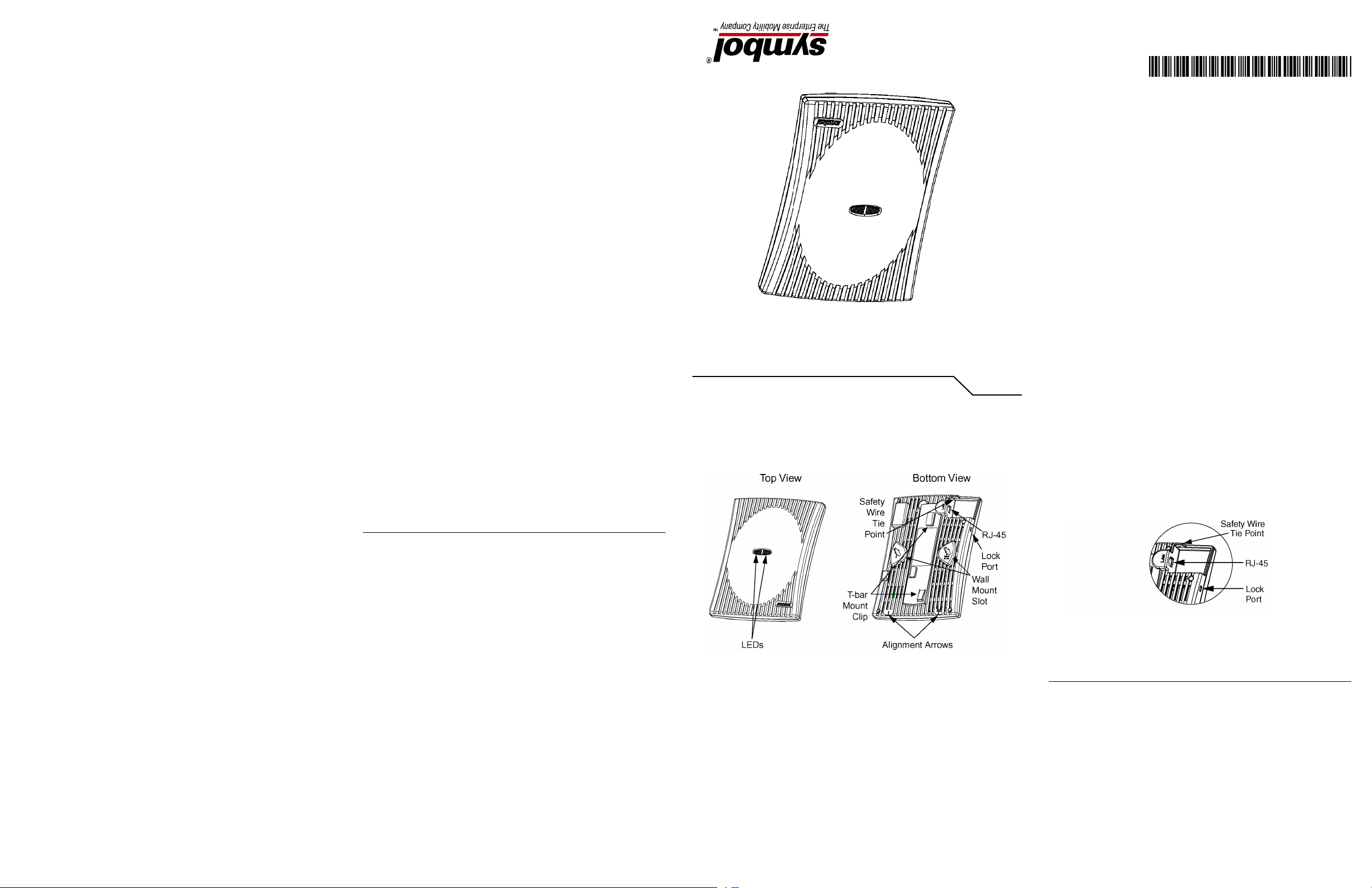
• One RJ-45 connector
• LED indicators
• Safety wire tie point
• Kensington-compatible lock port
• Slots for wall mounting
• Clips for mounting on a suspended ceiling T-bar
The AP 300 Access Port has one RJ-45 connector supporting an 10/100 Ethernet port and
requires 802.3af-compliant power from an external source.
The AP 300 Access Port comprises two 802.11 radios: an 802.11b/g radio operating in
the 2.4 to 2.5Ghz band and an 802.11a radio operating in the 4.9 to 5.875Ghz band. Each radio
has an embedded controller which runs local firmware used to perform the functions of the
lower 802.11 MAC. All upper MAC functions and MAC management are controlled by the
Wireless Switch.
Motherboard firmware enables the unit to boot after either a power up or a watchdog reset.
After self-boot, the motherboard sends an “I am alive” message into the network to be adopted
and loaded with the actual runtime code. The boot firmware on the motherboard and the
firmware downloaded from the switch can be updated via the Ethernet interface from the
Wireless Switch.
Lock Port
The lock port, compatible with Kensington-style security cables, is on the side of the case.
LED Indicators
The unit has LED activity indicators on the front of the case provide a status display indicating
error conditions, transmission, and network activity for the 802.11a (amber) radio or the
802.11b/g (green) radio.
Task 802.11a Activity LED Amber 802.11b/g Activity LED Green
Booting The amber LED flashes three times per second
until firmware is loaded. During boot, 802.11a
mobiles cannot associate.
Normal After adoption, the amber LED is steady or
flashes with 802.11a radio traffic.
Error The amber LED flashes once per second
if an error prevents the 802.11a radio from
operating normally.
The green LED flashes three times per second
until firmware is loaded. During boot,
802.11b/g mobiles cannot associate.
After adoption, the green LED is steady or
flashes with 802.11b/g radio traffic.
The green LED flashes once per second
if an error prevents the 802.11b/g radio from
operating normally.
Page 2
Installation Instructions
The AP 300 Access Port mounts either on a wall with wide-shoulder screws or on a suspended
ceiling T-bar. This unit is not designed for mounting on a desk.
To prepare for installation, perform the following steps:
1. Match the model number on the purchase order with the model numbers in the packing
list and on the case of the device shipped.
2. Verify that the contents of the box include the intended AP 300 Access Port and
mounting hardware:
Item Notes
WSAP-5110-100-WW 802.11a/b/g configuration.
3. Review site survey and network analysis reports to determine the location and
mounting position for the AP 300 Access Port.
4. Connect a CAT-5 cable to a compatible 802.3af power source and run the cable to the
installation site. Ensure that there is sufficient slack on the cable to perform the
installation steps.
Wall Mount
This mounting requires hanging the AP 300 Access Port along its width or length using the two
slots on the bottom of the unit. The AP 300 can be mounted onto any plaster, wood, or cement
wall surface using the provided wall anchors when necessary. The illustration shows a
lengthwise mount.
Mounting Hardware: Two wide-shoulder Phillips pan head self-tapping
screws.
(7) (9) (11) (13)
9. Verify the unit has power by observing that the LEDs are lit or flashing.
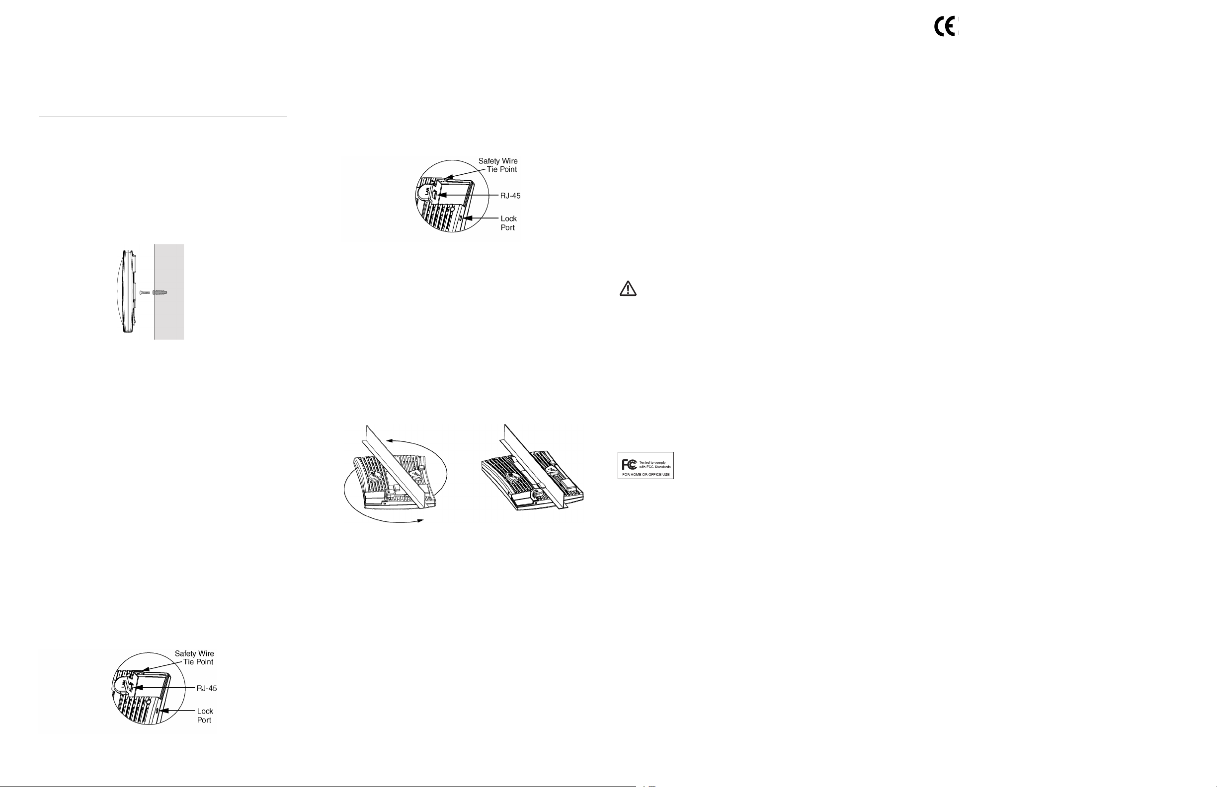
Suspended Ceiling T-Bar Mount
Ceiling mount requires holding the AP 300 Access Port up a gainst a T-bar of a suspended ceiling
grid and twisting the case onto the T-bar.
Ceiling Mount Hardware
• Safety wire (recommended) and security cable (optional)
Ceiling Mount Procedure
1. If required, loop a safety wire—with a diameter of at least .101cm (.04in.) but no more
than .158cm (.0625in.) —through the tie post and secure the loop.
2. If required, install and attach a security cable to the lock port.
3. Plug the Ethernet cable into the the unit and to a switch with an 802.3af-compatible
power source.
2
3
1
4. Face the bottom of the T-bar with the back of the case.
5. Orient the case by its length and the length of the T-bar.
6. Rotate the case in place 45 degrees clockwise, or about 10 o’clock.
7. Push the back of the case onto the bottom of the T-bar.
Regulatory Information
All Symbol devices are designed to be compliant with rules and regulations in locations they are
sold and will be labeled as required. Any changes or modifications to Symbol Technologies
equipment, not expressly approved by Symbol Technologies, could void the user’s authority to
operate the equipment.
Use only the approved antennas. Unauthorized antennas, modifications, or attachments could
cause damage and may violate regulations.
This device is to be used only with Symbol Technologies Wireless Switch.
Country Approvals
Regulatory markings are applied to the device signifying the radio (s) are approved for use in the
following countries: United States, Canada, Australia, Japan & Europe 1,2. Please refer to the
Symbol Declaration of Conformity (DoC) for details of other country markings. This is available at
http://www2.symbol.com/doc/.
Note 1: For 2.4GHz Products: Europe includes, Austria, Belgium, Croatia, Czech Republic, Croat-
ia, Cyprus, Denmark, Estonia, Finland, France, Germany, Greece, Hungary, Iceland, Ireland, Italy, Latvia, Liechtenstein, Lithuania, Luxembourg, Malta, Netherlands, Norway,
Poland, Portugal, Slovak Republic, Slovenia, Spain, Sweden, Switzerland, and the United Kingdom.
Note 2: The use of 5GHz RLAN’s has varying restrictions of use; please refer to the Symbol Dec-
laration of Conformity (DoC) for details.
Operation of the device without regulatory approval is illegal.
Frequency of Operation
The use on UNII (Unlicensed National Information Infrastructure) Band 1 5150-5250 MHz is restricted to indoor
use only.
FCC/EU RF Exposure Guidelines
Safety Information
The device complies with Internationally recognised standards covering Specific Absorption Rate
(SAR) related to human exposure to electromagnetic fields from radio devices. It is advisable to
use the device only in the normal operating position.
Remote and Standalone Antenna Configurations
To comply with FCC RF exposure requirements, antennas that are mounted externally at remote
locations or operating near users at stand-alone desktop or similar configurations must operate
with a minimum separation distance of 20 cm from all persons.
CE Marking and European Economic Area (EEA)
The use of 2.4GHz RLAN’s, for use through the EEA, have the following restrictions:
• Maximum radiated transmit power of 100 mW EIRP in the frequency range 2.400 -2.4835
GHz
• France, outside usage is restricted to 2.4-2.454 GHz
• Belgium, outside usage is restricted to 2.460-2.4835 GHz
• Italy requires a user license for outside usage.
The use of 5GHz RLAN’s has varying restrictions for use within the EEA; please refer to the
Symbol Declaration of Conformity (DoC) for details at http://www2.symbol.com/doc/
Statement of Compliance
Symbol Technologies, Inc., hereby, declares that this device is in compliance with the essential
requirements and other relevant provisions of Directive 1999/5/EC. A Declaration of
Conformity may be obtained from
http://www2.symbol.com/doc/
Other Countries
Mexico - Restrict Frequency Range to: 2.450 - 2.4835 GHz.
Sri Lanka - Restrict Frequency Range to: 2.400 – 2.430 GHz.
Wall Mount Hardware
• Two wide-shoulder Phillips pan head self-tapping screws
• Two wall anchors
• Safety wire (recommended) and security cable (optional)
Note: In the event that the original mounting screws are lost, the following screws
can be used instead:`(ANSI Standard) #6-18 X 0.875in. Type A or AB Self-Tapping Screw, or (ANSI Standard Metric) M3.5 X 0.6 X 20mm Type D Self-Tapping
Screw
Wall Mount Procedure
1. Orient the case on the wall by its width or length.
2. Using the arrows on one edge of the case as guides, move the edge to the midline of
the mounting area and mark points on the midline for the screws.
3. At each point, drill a hole in the wall, insert an anchor, screw into the anchor the wall
mounting screw and stop when there is 1mm between the screw head and the wall.
Note: When pre-drilling a hole the recommended hole size is 2.8mm (0.11in.) if the
screws are going directly into the wall and 6mm (0.23in.) if the provided wall
anchors are being used.
4. If required, loop a safety wire—with a diameter of at least .101cm (.04in.) but no more
than .158cm (.0625in.)—around the tie point and secure the loop.
5. If required, install and attach a security cable to the unit’s lock port.
6. Attach the Ethernet cable to the unit and to a switch with an 802.3af-compatible power
source.
5
6
4
7. Place the middle of each of the case’s mount slots over the screw heads.
8. Slide the case down along the mounting surface to hang the mount slots on the screw
heads.
(8) (10) (12) (14)
8. Rotate the case 45 degrees counter-clockwise. The clips click as they fasten to the T-bar.
9. Verify the unit has power by observing the LEDs.
Power Supply
This device is powered from a 802.3af compliant power source which is UL approved.
Radio Frequency Interference Requirements
This equipment has been tested and found to comply with the limits for a
Class B digital device, pursuant to Part 15 of the FCC rules. These limits are
designed to provide reasonable protection against harmful interference in a
radio frequency energy and, if not installed and used in accordance with the instructions, may
cause harmful interference to radio communications. However there is no guarantee that
interference will not occur in a particular installation. If this equipment does cause harmful
interference to radio or television reception, which can be determined by turning the equipment
off and on, the user is encouraged to try to correct the interference by one or more of the following
measures:
residential installation. This equipment generates, uses and can radiate
• Reorient or relocate the receiving antenna
• Increase the separation between the equipment and receiver
• Connect the equipment into an outlet on a circuit different from that to which the receiver is
connected
• Consult the dealer or an experienced radio/TV technician for help.
Radio Transmitters (Part 15)
This device complies with Part 15 of the FCC Rules. Operation is subject to the following two
conditions: (1) this device may not cause harmful interference, and (2) this device must accept any
interference received, including interference that may cause undesired operation.
Radio Frequency Interference Requirements – Canada
This Class B digital apparatus complies with Canadian ICES-003.
Cet appareil numérique de la classe B est conforme à la norme NMB-003 du Canada.
Radio Transmitters
This device complies with RSS 210 of Industry & Science Canada. Operation is subject to the
following two conditions: (1) this device may not cause harmful interference and (2) this device
must accept any interference received, including interference that may cause undesired operation.
Label Marking: The Term “IC:” before the radio certification only signifies that Industry Canada
technical specifications were met.
Customer Support
Symbol Technologies provides its customers with prompt and accurate customer support. Use
the Symbol Support Center as the primary contact for any technical problem, question or
support issue involving Symbol products.
If the Symbol Customer Support specialists cannot solve a problem, access to all technical
disciplines within Symbol becomes available for further assistance and support. Symbol
Customer Support responds to calls by e-mail, telephone or fax within the time limits set forth
individual contractual agreements.
When contacting Symbol Customer Support, please provide the following information:
• Device serial number
• Product name or model number
• Software type and version number
North American Contacts International Contacts
Inside North America, contact Symbol at:
Symbol Technologies, Inc.
One Symbol Plaza
Holtsville, New York 11742-1300
1-631-738-2400/1-800-SCAN 234
Fax: 1-631-738-5990
For warranty and service information, contact the Symbol Support Center: telephone 1-631738-6213 or 1-800-653-5350; fax: (631) 563-5410; or E-mail: support@symbol.com.
Web Support Sites and Additional Information
MySymbolCare http://www.symbol.com/services/msc/
Symbol Services Homepage http://symbol.com/services/
Symbol Software Updates http://symbol.com/services/downloads/
Symbol Developer Program http://software.symbol.com/devzone/
Symbol Knowledge Base http://kb.symbol.com/register.asp
Obtain additional information by contacting Symbol at:
• 1-800-722-6234, inside North America
• +1-631-738-5200, in/outside North America
• http://www.symbol.com/
Outside North America, contact Symbol at:
Symbol Technologies, Inc.
Symbol Place
Winnersh Triangle, Berkshire, RG41 5TP
United Kingdom
0800-328-2424 (Inside UK) /+44 118 945 7529 (Outside UK)
 Loading...