

Page 1

Wireless Switch 5000
Quick Setup Guide
WS 5000 Wireless Switch Version 1.1.4.30
72E-66722-01
Revision A
December 2003
www.symbol.com
Page 2

Copyright
Copyright © 2003 by Symbol Technologies, Inc. All rights reserved. No part of this publication
may be modified or adapted in any way, for any purposes without permission in writing from
Symbol Technologies, Inc. (Symbol). The material in this manual is subject to change without
notice. Symbol reserves the right to make changes to any product to improve reliability, function,
or design. No license is granted, either expressly or by implication, estoppels, or otherwise under
any Symbol Technologies, Inc., intellectual property rights. An implied license only exists for
equipment, circuits and subsystems contained in Symbol products. Symbol and the Symbol logo
are registered trademarks of Symbol Technologies, Inc.
Patents
This product is covered by one or more of the following U.S. and foreign Patents: U.S.
Patent No. 4,593,186; 4,603,262; 4,607,156; 4,652,750; 4,673,805; 4,736,095; 4,758,717;
4,760,248; 4,806,742; 4,816,660; 4,845,350; 4,896,026; 4,897,532; 4,923,281; 4,933,538;
4,992,717; 5,015,833; 5,017,765; 5,021,641; 5,029,183; 5,047,617; 5,103,461; 5,113,445;
5,130,520; 5,140,144; 5,142,550; 5,149,950; 5,157,687; 5,168,148; 5,168,149; 5,180,904;
5,216,232; 5,229,591; 5,230,088; 5,235,167; 5,243,655; 5,247,162; 5,250,791; 5,250,792;
5,260,553; 5,262,627; 5,262,628; 5,266,787; 5,278,398; 5,280,162; 5,280,163; 5,280,164;
5,280,498; 5,304,786; 5,304,788; 5,306,900; 5,324,924; 5,337,361; 5,367,151; 5,373,148;
5,378,882; 5,396,053; 5,396,055; 5,399,846; 5,408,081; 5,410,139; 5,410,140; 5,412,198;
5,418,812; 5,420,411; 5,436,440; 5,444,231; 5,449,891; 5,449,893; 5,468,949; 5,471,042;
5,478,998; 5,479,000; 5,479,002; 5,479,441; 5,504,322; 5,519,577; 5,528,621; 5,532,469;
5,543,610; 5,545,889; 5,552,592; 5,557,093; 5,578,810; 5,581,070; 5,589,679; 5,589,680;
5,608,202; 5,612,531; 5,619,028; 5,627,359; 5,637,852; 5,664,229; 5,668,803; 5,675,139;
5,693,929; 5,698,835; 5,705,800; 5,714,746; 5,723,851; 5,734,152; 5,734,153; 5,742,043;
5,745,794; 5,754,587; 5,762,516; 5,763,863; 5,767,500; 5,789,728; 5,789,731; 5,808,287;
5,811,785; 5,811,787; 5,815,811; 5,821,519; 5,821,520; 5,823,812; 5,828,050; 5,848,064;
5,850,078; 5,861,615; 5,874,720; 5,875,415; 5,900,617; 5,902,989; 5,907,146; 5,912,450;
5,914,478; 5,917,173; 5,920,059; 5,923,025; 5,929,420; 5,945,658; 5,945,659; 5,946,194;
5,959,285; 6,002,918; 6,021,947; 6,029,894: 6,031,830; 6,036,098; 6,047,892; 6,050,491;
6,053,413; 6,056,200; 6,065,678; 6,067,297; 6,082,621; 6,084,528; 6,088,482; 6,092,725;
6,101,483; 6,102,293; 6,104,620; 6,114,712; 6,115,678; 6,119,944; 6,123,265; 6,131,814;
6,138,180; 6,142,379; 6,172,478; 6,176,428; 6,178,426; 6,186,400; 6,188,681; 6,209,788;
6,209,789; 6,216,951; 6,220,514; 6,243,447; 6,244,513; 6,247,647; 6,308,061 6,250,551;
6,295,031; 6,308,061; 6,308,892; 6,321,990; 6,328,213; 6,330,244; 6,336,587; 6,340,114;
6,340,115; 6,340,119; 6,348,773; D305,885; D341,584; D344,501; D359,483; D362,453;
D363,700; D363,918; D370,478; D383,124; D391,250; D405,077; D406,581; D414,171;
D414,172; D418,500; D419,548; D423,468; D424,035; D430,158; D430,159; D431,562;
D436,104.
Invention No. 55,358; 62,539; 69,060; 69,187 (Taiwan); No. 1,601,796; 1,907,875;
1,955,269 (Japan); European Patent 367,299; 414,281; 367,300; 367,298; UK 2,072,832;
France 81/03938; Italy 1,138,713 (3/02)
ii
Page 3
Configuring the WS 5000 and Applying a WEP-128 Policy
Before using this quick setup guide, be sure to complete the tasks in the WS 5000 Wireless
Switch Quick Install Guide (QIG).
This document is written for the network installer or administrator who is familiar with their
Ethernet IP network but who is not necessarily trained on Symbol Technologies equipment. The
goal of this document is to show this user how to: (1) Connect the WS 5000 in a basic, flat switch
network topology and verify that it is properly connected, (2) Configure the WS 5000 to support
the network topology and (3) Apply a basic WEP 128 policy.
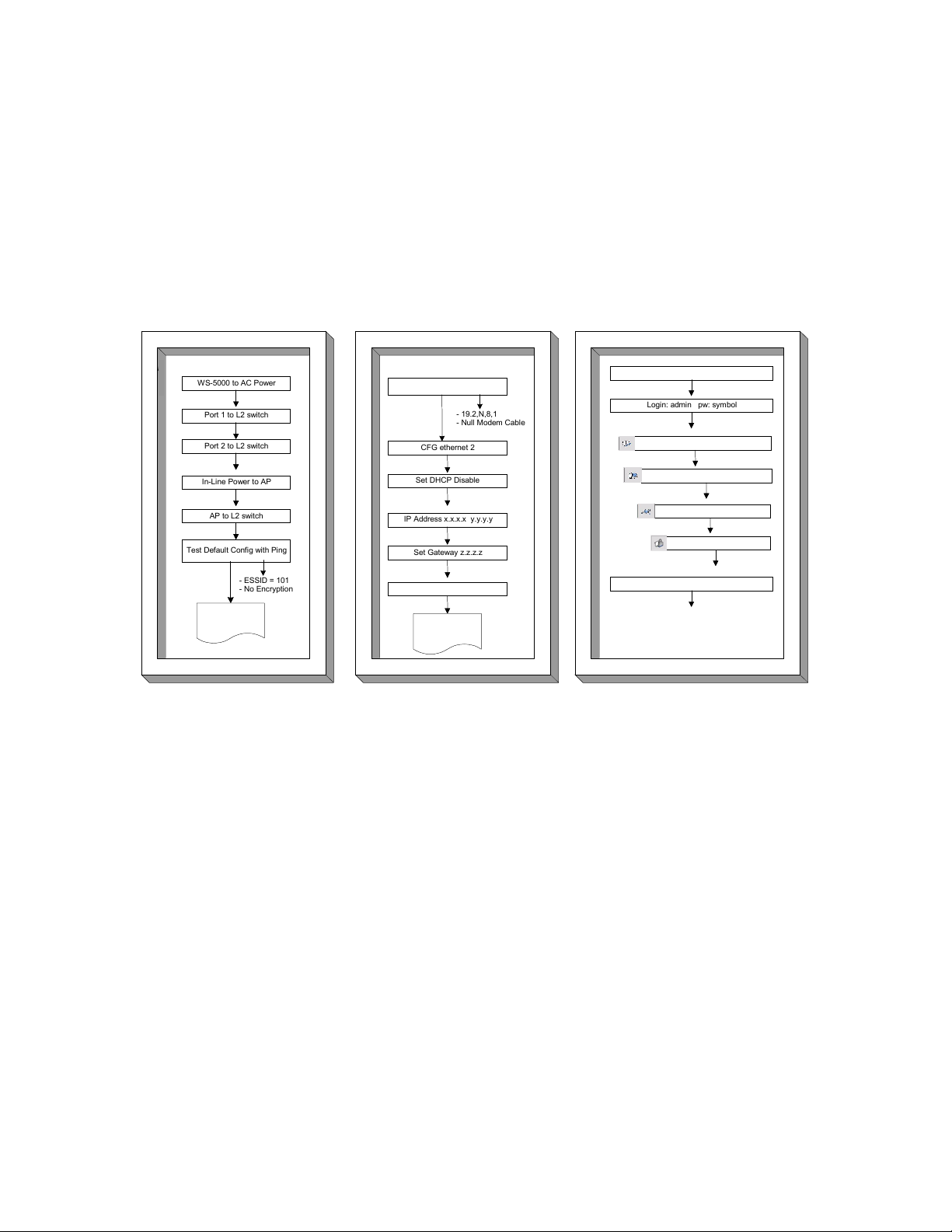
Step 2: Set IP Address of WS-5000
Step 1: Connect Hardware & Ping
Step 1: Connect Hardware & Ping
WS-5000 to AC Power
WS-5000 to AC Power
Port 1 to L2 switch
Port 1 to L2 switch
Port 2 to L2 switch
Port 2 to L2 switch
In-Line Power to AP
In-Line Power to AP
AP to L2 switch
AP to L2 switch
Test Default Config with Ping
Test Default Config with Ping
- ESSID = 101
- ESSID = 101
- No Encryption
- No Encryption
Step 2: Set IP Address of WS-5000
Serial Console to CLI
Serial Console to CLI
- 19.2,N,8,1
- 19.2,N,8,1
- Null Modem Cable
- Null Modem Cable
CFG ethernet 2
CFG ethernet 2
Set DHCP Disable
Set DHCP Disable
IP Address x.x.x.x y.y.y.y
IP Address x.x.x.x y.y.y.y
Set Gateway z.z.z.z
Set Gateway z.z.z.z
Show Ethernet 2
Show Ethernet 2
Step 3: Config Secure WLAN
Step 3: Config Secure WLAN
Connect HTTPS to WS-5000
Connect HTTPS to WS-5000
Login: admin pw: symbol
Login: admin pw: symbol
Create Wireless Switch Policy
Create Wireless Switch Policy
Create Access Port Policy
Create Access Port Policy
Create WLAN Policy
Create WLAN Policy
Create Security Policy
Create Security Policy
Test new secure WLAN with Ping
Test new secure WLAN with Ping
Goto Step #2
Goto Step #2
Goto Step #3
Goto Step #3
Done
Done
Figure 1: The WS 5000 Setup Steps
When the user has completed this setup guide, the WS 5000 switch will be able to support their
WLAN with the basic, minimum configuration recommended by Symbol Technologies, Inc. The
time required to complete these three steps is normally less than an hour.
Step 1: Connecting the WS 5000 to the Network
This step should take less than 15 minutes to complete.
Refer to Figure 2 for cabling details and specific device configurations (required for the ping test).
All the wireless LAN (WLAN) devices are connected to Layer-2 switch A and all the wired LAN
devices are connected to Layer-2 switch B. Connect Layer-2 switch A to Ethernet port 1 on the
WS 5000 (labeled WLAN 0) to connect the wireless traffic, and connect Layer-2 switch B to
Ethernet port 2 on the WS 5000 (labeled LAN 1) to connect the wired LAN traffic.
1
Page 4
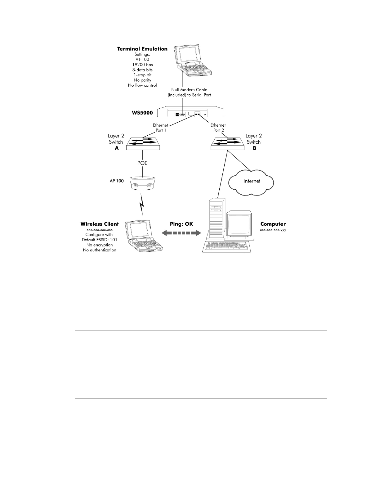
Figure 2: The Network Topology
Verifying the Connections
If the WS 5000 is connected correctly, devices on the wireless LAN should be able to connect to
devices on the LAN. To test the connection between the wireless client device and the computer
shown in Figure 2, from the wireless client, enter:
C:> ping xxx.xxx.xxx.yyy
PING xxx.xxx.xxx.yyy (xxx.xxx.xxx.yyy): 56 data bytes
64 bytes from xxx.xxx.xxx.yyy: icmp_seq=0 ttl=127 time=0.39 ms
64 bytes from xxx.xxx.xxx.yyy: icmp_seq=1 ttl=127 time=0.327 ms
64 bytes from xxx.xxx.xxx.yyy: icmp_seq=2 ttl=127 time=0.33 ms
64 bytes from xxx.xxx.xxx.yyy: icmp_seq=3 ttl=127 time=0.309 ms
--- xxx.xxx.xxx.yyy ping statistics --4 packets transmitted, 4 packets received, 0% packet loss
round-trip min/avg/max = 0.309/0.338/0.39 ms
C:>
Because the wireless client was able to connect to a computer on the network through the switch,
the network connections are functioning properly. If the ping test fails, make sure the target
computer is turned on, connected to the network, and is configured with the IP address used in
the ping.
2
Page 5

Step 2: Initial Configuration Using the CLI
This step should take less than 10 minutes to complete.
Note: In this guide, MAC and IP addresses have been changed to protect actual devices from
unauthorized access.
To configure the WS 5000 with site-specific IP addressing and network policies, connect the
administrative PC to the WS 5000 with the serial cable (as discussed in the QIG). Once the basic
WS 5000 network configuration is complete, administrators can create a policy as discussed in
“Basic WS 5000 Configuration.”
The terminal emulation window will display the Wireless Switch login screen (if the login prompt
does not display, press <Enter> until the Command Line Interface (CLI) appears:
Wireless Switch…
userid:
Enter admin at the userid prompt:
userid:admin<enter>
Enter symbol at the password prompt:
password:symbol<enter>
The system displays the following:
Retrieving user and system information...
Setting user permissions flags..
Checking KDC access permissions...
Welcome...
System information...
System Name : WS5000
Descriptions : WS 5000 Wireless Network
Software Ver. : 1.1.4.30
Licensed to : Symbol Technologies
Copyright : Copyright (c) 2000-2003. All rights reserved.
Serial Number : 00A0xxxxxxxx
Number of Licenses : 30
Max Access Port : 30
Max Mobile Clients : 4096
Active Switch Policy : Default Wireless Switch Policy
Emergency Switch Policy : Not defined
Switch Uptime : 00d:00h:00m
# of Unassigned Access Ports : 0
WS5000>
Verify that the software version shown in the Software Ver. field is the current version by
comparing this value with that on the Symbol website at:
http://www.symbol.com/services/downloads/download_switchwireless.html
If the WS 5000 software version is older than what is on the Symbol Technologies, Inc. website,
then refer to the Release Notes for this WS 5000 for instructions on upgrading the software.
The following steps create a typical network configuration. Modify this configuration as necessary.
3
Page 6

Configuring Ethernet Ports
WS5000>config<enter>
The system enters into the configuration mode and displays the following prompt:
WS5000.(Cfg)>
To change Ethernet port 2 configuration:
WS5000.(Cfg)>Ethernet<enter>
The system enters into Ethernet configuration mode. To configure the Ethernet port parameters,
enter the following:
WS5000.(Cfg).Ethernet> 2<enter>
Where: 2 is the port being configured. Only port 2 needs to be configured for this procedure.
To disable DHCP:
WS5000.(Cfg).Ethernet.[2]>set dhcp disable<enter>
Symbol recommends assigning static IP addresses for Ethernet ports.
To change the Ethernet port 2 IP address:
This step is required to manage the WS 5000.
WS5000.(Cfg).Ethernet.[2]>ipaddress <address><net_mask><enter>
Where: <address> is the IP address assigned to this port.
Where: <net_mask> is the subnet mask for this port.
For example:
WS5000.(Cfg).Ethernet.[2]>ipaddress 192.168.123.102 255.255.255.0
To configure a gateway:
WS5000.(Cfg).Ethernet.[2]>set gateway <address><enter>
Where: <address> is the IP address for the gateway device.
To specify a DNS server:
WS5000.(Cfg).Ethernet.[2]>set dns <address><enter>
Where: <address> is the IP address of the DNS server.
4
Page 7

To verify information about an Ethernet port:
WS5000.(Cfg)>show ethernet 2<enter>
The system displays information about Ethernet port 2 (as opposed to port 1):
WS5000.(Cfg)> show ethernet 2
Name : Ethernet 2
Network Interface Card # : 2
Description : Ethernet Adapter
MAC Address : 00:A0:xx:xx:xx:xx
Status : Enable
Online : Yes
Speed : 100
DHCP status : Disable
IP Address : 192.168.91.153
Network Mask : 255.255.255.0
Port type (trunk/non-trunk) : Non-Trunk
VLAN Tags seen : None
Up-Time : 00d:00h:16m
Transmit packets : 852
Received packets : 12783
Gateway details :
1. 192.168.91.2.
DNS details :
1. 192.168.95.1.
2. 192.168.95.229.
WS5000.(Cfg)>
After the Ethernet port has been configured and verified, type exit to return to the Console
command prompt.
The switch installation is complete. The serial cable can be disconnected from the administrative
PC. The next section describes a basic switch security policy configuration using the browser
interface of a PC connected to the same subnet as Ethernet port 2 on the WS 5000.
5
Page 8

Step 3: Creating a Policy Using the GUI
This step should take less than 15 minutes to complete. When you finish this step, the WS 5000
will be operating with a WEP 128 security policy.
The WS 5000 GUI simplifies creating policies. To use
the GUI, start a web browser on a computer
connected like the computer on the wired LAN in
Figure 2. Direct the browser to the secure connection
at 'https://nnn.nnn.nnn.nnn', (not http://) where
nnn.nnn.nnn.nnn is the IP address of the Ethernet
port 2 on the WS 5000. (In the example in “To
change the Ethernet port 2 IP address:” this IP
address is 192.168.123.102.) The browser should be
able to connect immediately, and display the login
screen as shown here.
Enter the User ID admin, and Password symbol. (Both are case-sensitive.) Then click the Login
button. The WS 5000 main window appears.
This section will explain how to replace the Default Wireless Switch Policy and the Default Access
Port Policy with a new switch-level WEP 128 policy. (The Default Ethernet Policy does not need
to be changed.) To do this, users will need to create a Security Policy and define a WLAN that will
use this new Security Policy. The policy wizard will guide the user through the procedures.
On the left panel of this
main window, notice
that the Default
Wireless Switch Policy
(highlighted) includes a
Default Ethernet Policy,
which applies to both
Ethernet ports, and a
Default Access Port
Policy which applies to
any connected Access
Ports.
Basic WS 5000 Configuration
The following steps to enable WEP 128 security for a new ESSID are simple yet powerful. The
WS 5000 GUI can also be used to create a wide variety of complex network policies. Using the
GUI to create these advanced policies requires a thorough understanding of concepts that are
beyond the scope of this document. For a complete explanation of WS 5000 policies, see the
System Reference Guide included on the WS 5000 CD.
6
Page 9

These instructions apply to WS 5000s with the Type value set to Primary. If this WS 5000 is
configured as Standby, no Access Ports will be adopted and no policies will be applied.
To change the Type setting:
1. From the toolbar, select System Settings → Standby Management…
2. Click Primary for the Wireless Switch Mode selection.
3. Click Apply, then click Close.
The main screen should now show the Type as Primary.
To create a new WLAN and a security policy:
1. On the main WS 5000 window, select the Default Wireless Switch Policy from the tree
view on the left panel of the main screen.
2. Click Properties on the upper right corner of the main screen. The Wireless Switch
Policy Manager screen appears.
3. From the Wireless Switch Policy
Manager screen, click Create.
The Create a New Wireless Switch
Policy Wizard screen appears.
4. On the Create a New Wireless S
Policy Wizard screen, enter a Name
and (optional) Description for the
Wireless Switch policy. In this
example, the Name is QSG Wireless
Switch Policy and the Description is
the First wireless switch policy. Click
Next to display the Wireless Switch
Policy screen.
witch
7
Page 10

5. On the Wireless Switch Policy
screen, select the appropriate
Country. The Channel and Power
Level settings adjust to the country
selected. Click Next to display
available Access Port policies.
6. On this Wireless Switch Policy
screen, click Create to define a new
Access Port policy. The Create a
New Access Port Policy Wizard
screen appears.
7. On the Create a New Access Port
Policy Wizard screen, enter a Name
and (optional) Description for this
Access Port policy. In this example,
the Name is QSG Access Port Policy
and the Description is First access
port policy.
Click Next to start the process of
creating a WLAN for this Access Port
policy.
8
Page 11

8. On this Access Port Policy screen,
click Create. The Create a New
WLAN Wizard screen appears.
9. On the Create a New WLAN Wizard
screen, enter a Name and (optional)
Description for this WLAN. For this
example, the Name is QSG First
WLAN and the Description is First
Wireless LAN.
Click Next to display the WLAN
details screen.
10. Enter an ESSID. In this example, the
ESSID is QSGESSID.
Click Next to define the security p
olicy
for this WLAN.
9
Page 12

11. On this WLAN screen click Create to
define a new security policy. The
Create a New Security Policy Wizard
screen appears.
12. On the Create a New Security
Policy Wizard screen, enter a
Name and (optional) Description
for this new security policy. In this
example, the Name is QSG First
Security Policy and the Description
is First security policy.
13. Click the WEP checkbox to enable
encryption of wireless traffic and
click Next. The Select Encryption
Key Management screen appears.
14. On this Select Encryption Key
Management screen, click
Manually Pre-Shared Key and
click Next to display the WEP
Encryption Key Settings screen.
10
Page 13

15. For wireless clients using Symbol
Technologies adapters, enter a
Pass Key value and click
Generate. Remember this Pass
Key as it will be needed to
configure wireless clients. Click
Next and skip to step 17.
16. For wireless clients using non-Symbol
Technologies adapters, enter a 26character hexadecimal value for
Key#1. Remember this 26-character
value as it will be needed to configure
wireless clients. Click Next to display
the Security Policy confirmation
screen.
17. From this Security Policy
confirmation screen, click Finish to
save the policy and exit the
Security Policy Wizard and display
the WLAN Wizard screen. The
newly created security policy will
now be attached to the WLAN.
11
Page 14

18. From the WLAN Wizard screen,
select the security policy just created.
In this example, this is QSG First
Security Policy. Click Next to display
the next WLAN Wizard screen.
19. From this WLAN Wizard screen, click
Next to display the WLAN creation
confirmation screen.
20. From this WLAN Wizard confirmation
screen, click Finish to save the
WLAN policy and exit the WLAN
Wizard.
The Access Port Policy Wizard
screen appears which allows the
newly created WLAN to be attached
to the Access Port policy.
12
Page 15

21. On the Access Port Policy Wizard
screen, select the WLAN policy just
created and click the >> button to
move the policy from the Available
box to the Selected box. The Access
Port Policy Wizard screen redisplays
showing the WLAN policy in the
Selected box.
22. From this Access Port Policy Wizard
screen, click Next to apply the
Network Policy to this WLAN.
23. Click Next without making any
changes to the settings on this
Access Port Policy Wizard screen.
The Bandwidth Allocation screen
appears.
13
Page 16

24. Click Next without making any
changes to the bandwidth settings on
this Access Port Policy Wizard
screen. The Access Port Policy
confirmation screen appears.
25. On the Access Port Policy
confirmation screen, click Finish to
save this Access Port policy and exit
the Access Port Policy Wizard. The
Wireless Switch Policy Wizard screen
appears to allow the newly created
Access Port Policy to be attached to
the switch policy.
26. From the Wireless Switch Policy
Wizard screen, select the Access Port
Policy just created (in this example,
QSG Access Port Policy) and click the
>> button to move the policy from the
Available box to the Selected box.
The Wireless Switch Policy Wizard
screen redisplays showing the Access
Port Policy in the Selected box.
14
Page 17

27. From this Wireless Switch Policy
Wizard screen, click Next to display
the Adoption List Allow screen.
28. Click Next without making any
changes to this Wireless Switch Policy
Wizard screen. The Adoption List
Disallow screen appears.
29. Click Next without making any
changes to this Wireless Switch Policy
Wizard screen. The Unknown Access
Ports/Access Points screen appears.
15
Page 18

30. Click the Allow adoption and use
Access Port Policy button and click
Next to display the Wireless Switch
Policy confirmation screen.
31. From this Wireless Switch Policy
confirmation screen click Finish to
save this Wireless Switch policy and
exit the Wireless Switch Policy
Wizard. The Wireless Switch Policy
Manager screen appears.
32. From the Wireless Switch Policy
Manager screen, select the
Wireless Switch Policy just created
(in this example, QSG Wireless
Switch Policy) and click Activate. A
warning box appears.
16
Page 19

33. From the Warning box, click OK. The Wireless Switch
Policy Manager screen reappears.
34. From the Wireless Switch Policy
Manager screen, click Close. The
WS 5000 main screen reappears.
35. Notice that the policy tree on the left panel of the WS 5000 main screen shows the new
policy (QSG Wireless Switch Policy), which makes WEP 128 active for this WS 5000
(and all attached Access Ports and Mobile Units). Notice that the new switch-level policy
also includes the newly created QSG Access Port Policy, which in turn controls the QSG
First WLAN policy with the new ESSID.
17
Page 20

To verify that the new policy is working:
1. Reconfigure wireless clients to match these new settings (ESSID, etc.) as shown in
Figure 2.
2. Reissue the ping test done in “Verifying the Connections” to confirm that a wireless client
can still reach the wired LAN. Or, use the GUI to confirm connectivity with mobile units.
To verify the connectivity of mobile units using the GUI, click Mobile Units (highlighted)
on the left panel of the WS 5000 main screen (shown below). The MU View screen
appears.
3. Select a mobile
unit and click
Properties. The
MU Properties
screen appears.
From the MU Properties screen, the identity and
connection status of the selected mobile unit
can be verified. Notice the wide variety of
identification, status, and traffic information
available for this mobile device.
Conclusion
The WS 5000 is now fully operational and secured with WEP 128. No additional configuration is
required unless desired. To create additional policies, refer to the System Reference Guide on
the CD included with this WS 5000.
18
 Loading...