

Page 1

WS 2000 Wireless Switch
System Reference
WS 2000 Wireless Switch Version 1.0
72E-67701-01
Rev A
March 2004
www.symbol.com
Page 2

Copyright
Copyright © 2004 by Symbol Technologies, Inc. All rights reserved. No part of this
publication may be modified or adapted in any way, for any purposes without permission in
writing from Symbol Technologies, Inc. (Symbol). The material in this manual is subject to
change without notice. Symbol reserves the right to make changes to any product to
improve reliability, function, or design. No license is granted, either expressly or by
implication, estoppels, or otherwise under any Symbol Technologies, Inc., intellectual
property rights. An implied license only exists for equipment, circuits and subsystems
contained in Symbol products. Symbol and the Symbol logo are registered trademarks of
Symbol Technologies, Inc.
Patents
This product is covered by one or more of the following U.S. and foreign Patents: U.S.
Patent No. 4,593,186; 4,603,262; 4,607,156; 4,652,750; 4,673,805; 4,736,095; 4,758,717;
4,760,248; 4,806,742; 4,816,660; 4,845,350; 4,896,026; 4,897,532; 4,923,281; 4,933,538;
4,992,717; 5,015,833; 5,017,765; 5,021,641; 5,029,183; 5,047,617; 5,103,461; 5,113,445;
5,130,520; 5,140,144; 5,142,550; 5,149,950; 5,157,687; 5,168,148; 5,168,149; 5,180,904;
5,216,232; 5,229,591; 5,230,088; 5,235,167; 5,243,655; 5,247,162; 5,250,791; 5,250,792;
5,260,553; 5,262,627; 5,262,628; 5,266,787; 5,278,398; 5,280,162; 5,280,163; 5,280,164;
5,280,498; 5,304,786; 5,304,788; 5,306,900; 5,324,924; 5,337,361; 5,367,151; 5,373,148;
5,378,882; 5,396,053; 5,396,055; 5,399,846; 5,408,081; 5,410,139; 5,410,140; 5,412,198;
5,418,812; 5,420,411; 5,436,440; 5,444,231; 5,449,891; 5,449,893; 5,468,949; 5,471,042;
5,478,998; 5,479,000; 5,479,002; 5,479,441; 5,504,322; 5,519,577; 5,528,621; 5,532,469;
5,543,610; 5,545,889; 5,552,592; 5,557,093; 5,578,810; 5,581,070; 5,589,679; 5,589,680;
5,608,202; 5,612,531; 5,619,028; 5,627,359; 5,637,852; 5,664,229; 5,668,803; 5,675,139;
5,693,929; 5,698,835; 5,705,800; 5,714,746; 5,723,851; 5,734,152; 5,734,153; 5,742,043;
5,745,794; 5,754,587; 5,762,516; 5,763,863; 5,767,500; 5,789,728; 5,789,731; 5,808,287;
5,811,785; 5,811,787; 5,815,811; 5,821,519; 5,821,520; 5,823,812; 5,828,050; 5,848,064;
5,850,078; 5,861,615; 5,874,720; 5,875,415; 5,900,617; 5,902,989; 5,907,146; 5,912,450;
5,914,478; 5,917,173; 5,920,059; 5,923,025; 5,929,420; 5,945,658; 5,945,659; 5,946,194;
5,959,285; 6,002,918; 6,021,947; 6,029,894: 6,031,830; 6,036,098; 6,047,892; 6,050,491;
6,053,413; 6,056,200; 6,065,678; 6,067,297; 6,082,621; 6,084,528; 6,088,482; 6,092,725;
6,101,483; 6,102,293; 6,104,620; 6,114,712; 6,115,678; 6,119,944; 6,123,265; 6,131,814;
6,138,180; 6,142,379; 6,172,478; 6,176,428; 6,178,426; 6,186,400; 6,188,681; 6,209,788;
6,209,789; 6,216,951; 6,220,514; 6,243,447; 6,244,513; 6,247,647; 6,308,061 6,250,551;
6,295,031; 6,308,061; 6,308,892; 6,321,990; 6,328,213; 6,330,244; 6,336,587; 6,340,114;
6,340,115; 6,340,119; 6,348,773; D305,885; D341,584; D344,501; D359,483; D362,453;
D363,700; D363,918; D370,478; D383,124; D391,250; D405,077; D406,581; D414,171;
D414,172; D418,500; D419,548; D423,468; D424,035; D430,158; D430,159; D431,562;
D436,104.
Invention No. 55,358; 62,539; 69,060; 69,187 (Taiwan); No. 1,601,796; 1,907,875;
1,955,269 (Japan); European Patent 367,299; 414,281; 367,300; 367,298; UK 2,072,832;
France 81/03938; Italy 1,138,713 (3/02)
Page 3

WS 2000 Wireless Switch System Reference Guide
Table of Contents
Chapter 1.
Overview............................................................................................6
WS 2000 Wireless Switch System Reference Guide....................................................6
About this Document.............................................................................................6
Document Conventions.........................................................................................6
System Overview...........................................................................................................7
Management of Access Ports................................................................................7
Hardware Overview.......................................................................................................8
Technical Specifications........................................................................................8
Software Overview ........................................................................................................9
Operating System (OS) Services ..........................................................................9
Cell Controller Services.........................................................................................9
Gateway Services................................................................................................10
Chapter 2. Features .......................................................................................... 11
802.11a Support..........................................................................................................11
802.11b Support..........................................................................................................11
Access Ports................................................................................................................12
Gateway Services........................................................................................................13
Network Address Translation (NAT)....................................................................13
WS 2000 Wireless Switch Firewall......................................................................13
DHCP Client and Server......................................................................................14
Layer 3 Routing ...........................................................................................................14
Overview..............................................................................................................14
SNMP Management Support.......................................................................................14
WEP 64 (40-bit key) ....................................................................................................15
WEP 128 (104-bit Key)................................................................................................15
802.1x with RADIUS Authentication............................................................................15
802.1x with Shared Key Authentication.......................................................................16
Kerberos Authentication..............................................................................................16
KeyGuard-MCM Support.............................................................................................17
Wireless Protected Access (WPA)..............................................................................17
Chapter 3. Getting Started ................................................................................18
Getting Started Overview ............................................................................................18
Installing the Switch.............................................................................................18
Set up Communication to the Switch ..................................................................18
Changing the Administrator Password................................................................20
Configuring the Switch.........................................................................................21
Step 1: Configure the LAN Interface ...........................................................................21
Defining the Subnets...........................................................................................22
Step 2: Configure Subnets ..........................................................................................23
The DHCP Configuration.....................................................................................24
Step 3: Configure the WAN Interface..........................................................................26
Communicating with the Outside World..............................................................26
Setting Up Point-to-Point over Ethernet (PPPoE) Communication.....................27
Step 4: Enable Wireless LANs (WLANs).....................................................................28
Wireless Summary Area......................................................................................29
Access Port Adoption..........................................................................................30
Step 5: Configure WLANs ...........................................................................................30
Step 6: Configure WLAN Security...............................................................................31
Setting the Authentication Method ......................................................................32
Setting the Encryption Method ............................................................................33
Copyright © 2004 Symbol Technologies, Inc. All Rights Reserved 3
WS 2000 Wireless Switch: 1.0 Date of last Revision: March 2004
Page 4

WS 2000 Wireless Switch System Reference Guide
Mobile Unit Access Control List (ACL) ................................................................37
Step 7: Configure Access Ports...................................................................................37
Step 8: Configure Subnet Access ...............................................................................39
The Access Overview Table................................................................................40
The Access Exception Area ................................................................................40
Chapter 4. Advanced Configuration..................................................................43
WLAN—How to Configure Advanced Settings............................................................43
WLAN—Setting Default Access Port Settings.............................................................44
WLAN—Advanced Access Port Settings....................................................................47
Gateway—How to Configure Network Address Translation (NAT).............................50
Gateway—How to Configure the WS 2000 Firewall ...................................................52
Always On Firewall Filters...................................................................................52
Configurable Firewall Filters................................................................................53
Gateway—How to Configure Static Routes ................................................................54
Defining Routes...................................................................................................55
Setting the RIP Configuration..............................................................................55
Security—How to Configure 802.1x EAP Authentication............................................56
Security—How to Configure Kerberos Authentication ................................................59
Security—How to Specify a Network Time Protocol (NTP) Server.............................60
Chapter 5. System Administration.....................................................................61
Overview......................................................................................................................61
Switch Settings............................................................................................................61
WS 2000 Wireless Switch LED Functions...........................................................61
Changing the Name of the Switch.......................................................................62
Change the Location and Country Settings of the WS 2000...............................63
How to Restart the WS 2000 Wireless Switch ....................................................64
Updating the WS 2000 Wireless Switch’s Firmware...........................................64
System Configuration..................................................................................................66
Exporting and Importing Wireless Switch Settings..............................................66
How to Restore Default Configuration Settings...................................................68
Restoring Default Configuration Settings Using the Command Line Interface...69
Remote Administration................................................................................................70
How to Configure SNMP Traps...........................................................................70
Configure Administrator Access..........................................................................75
Statistics and Logs ......................................................................................................77
Access Port Statistics..........................................................................................77
Subnet Statistics..................................................................................................80
WAN Statistics.....................................................................................................82
Setting Up and Viewing the System Log.............................................................84
Chapter 6. Retail Use Cases............................................................................. 86
Background..................................................................................................................86
The Plan ......................................................................................................................87
Configuring the System Settings.................................................................................88
Configuring the Subnets..............................................................................................91
Configuring the WAN Interface....................................................................................97
Configuring Network Address Translation (NAT)........................................................98
Inspecting the Firewall...............................................................................................100
Configuring the Access Ports....................................................................................100
Configuring the WLANs.............................................................................................105
Configuring the Printer WLAN...........................................................................106
Configuring the POS WLAN..............................................................................107
Setting Subnet Access ..............................................................................................108
Configuring the Clients......................................................................................110
Testing Connections..................................................................................................110
Copyright © 2004 Symbol Technologies, Inc. All Rights Reserved 4
WS 2000 Wireless Switch: 1.0 Date of last Revision: March 2004
Page 5

WS 2000 Wireless Switch System Reference Guide
Chapter 7. A Field Office Example..................................................................111
Background................................................................................................................111
The Plan ....................................................................................................................112
Configuring the System Settings...............................................................................113
Setting Access Control......................................................................................115
Configuring the LAN..................................................................................................117
Configuring the WAN.................................................................................................121
Setting Up Network Address Translation ..................................................................123
Confirm Firewall Configuration..................................................................................125
Adopting Access Ports ..............................................................................................125
Configuring the WLANs.............................................................................................127
Configuring the Access Ports....................................................................................130
Configuring Subnet Access.......................................................................................135
Installing the Access Ports and Testing ....................................................................136
Appendix A. Sample Configuration File.............................................................137
Index 147
Copyright © 2004 Symbol Technologies, Inc. All Rights Reserved 5
WS 2000 Wireless Switch: 1.0 Date of last Revision: March 2004
Page 6
WS 2000 Wireless Switch System Reference Guide
Chapter 1. Overview
WS 2000 Wireless Switch System Reference Guide
This guide is intended to support administrators responsible for understanding, configuring
and maintaining the Wireless Switch. This document provides information for the system
administrator to use during the initial setup and configuration of the system. It also serves as
a reference guide for the administrator to use while updating or maintaining the system.
About this Document
We recommend viewing this online system reference guide with Internet Explorer 5.0 and
higher or Netscape Navigator 4.7 or higher on a Microsoft Windows based PC. Viewing
this document under other configurations may produce undesirable results.
Document Conventions
Notes
Notes are displayed in blue italic text and indicate a tip or requirement. Warning Warnings
are displayed in red italic text and indicate a loss of data or potential injury. GUI Screen text
Indicates monitor screen dialog / output from the graphical user interface accessed from any
web browser on the network.
Warnings
Warnings are displayed in red italic text and indicate a loss of data or potential injury.
Copyright © 2004 Symbol Technologies, Inc. All Rights Reserved 6
WS 2000 Wireless Switch: 1.0 Date of last Revision: March 2004
Page 7

GUI Screen text
Indicates monitor screen dialog / output from the graphical user interface accessed from any
web browser on the network.
System Overview
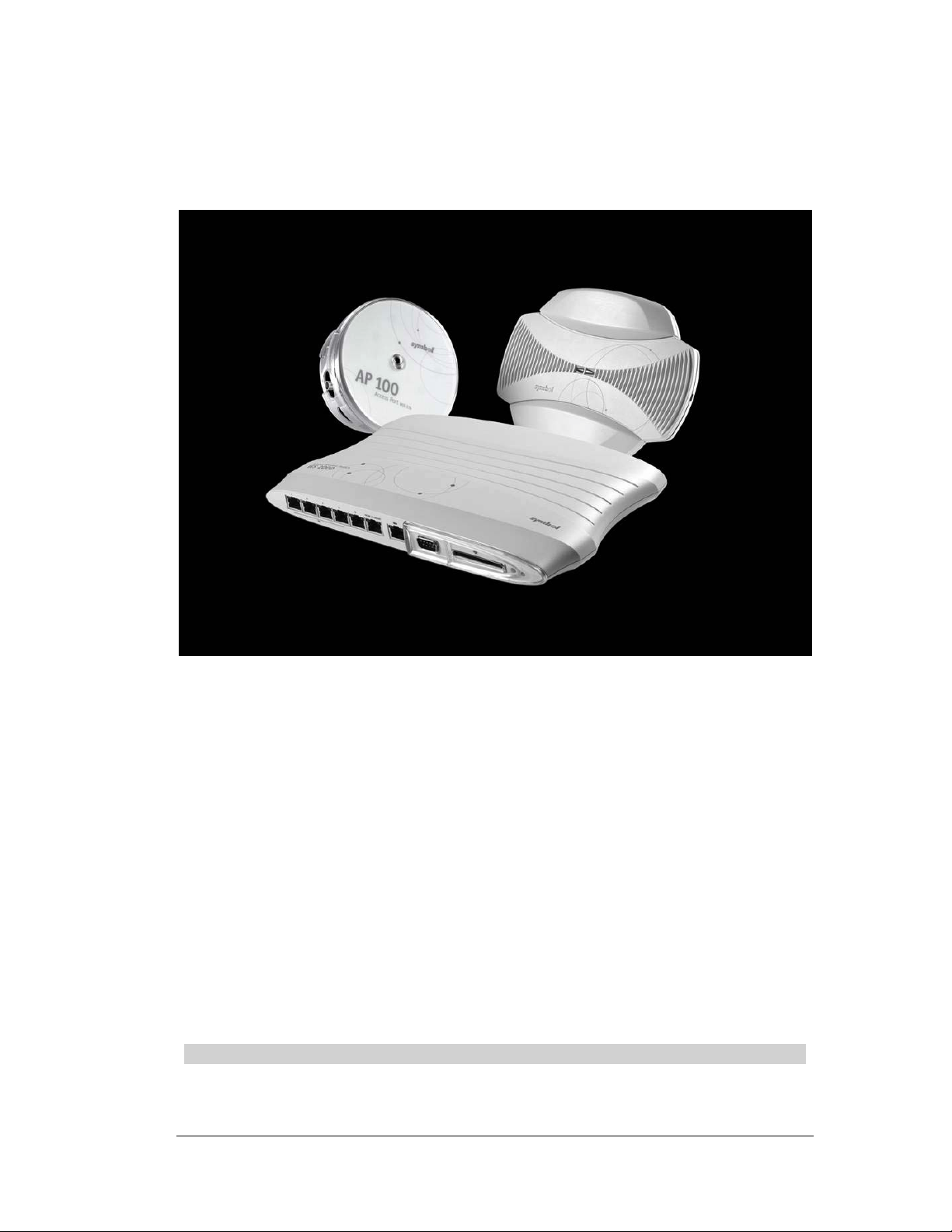
The WS 2000 Wireless Switch provides a low-cost, feature-rich wireless switch for sites
with one to six Access Ports. The WS 2000 Wireless Switch works at the center of a
network’s infrastructure to seamlessly and securely combine wireless LANs (WLANs) and
wired networks. The switch sits on the network. Wireless Access Ports connect to one of the
six available ports on the switch and the external wired network (WAN) connects to a single
10/100 Mbit/sec. WAN port.
Mobile units (MUs) associate with the switch via an Access Port. Once an MU contacts the
switch, the switch cell controller services attempt to authenticate the device for access to the
network.
The WS 2000 Wireless Switch acts as a WAN/LAN gateway and a wired/wireless switch.
Management of Access Ports
This wireless switch provides six 10/100 Mbit/sec. LAN ports for internal wired or wireless
traffic. Four of these ports provide IEEE 802.3af-compliant Power over Ethernet (PoE)
support for devices that require power from the Ethernet connection (such as Access Ports).
Administrators can configure the six ports to communicate with a private LAN or with an
Access Port for a wireless LAN (WLAN). The switch provides three extended service set
identifiers (ESSIDs) for each Access Port connected to the switch.
System Overview
Firewall Security
The LAN and Access Ports are placed behind a user configurable firewall that provides
stateful packet inspection. The wireless switch performs network address translation (NAT)
on packets passing to and from the WAN port. This combination provides enhanced
security by monitoring communication with the wired network.
Wireless LAN (WLAN) Security
Administrators can configure security settings independently for each ESSID. Security
settings and protocols available with this switch include:
• Kerberos
• WEP-40
• WEP-128
• 802.1x with RADIUS
• 802.1x with Shared Key
• KeyGuard-MCM
• WPA
Copyright © 2004 Symbol Technologies, Inc. All Rights Reserved 7
WS 2000 Wireless Switch: 1.0 Date of last Revision: March 2004
Page 8
Hardware Overview
The WS 2000 Wireless Switch provides a fully integrated solution for managing every
aspect of connecting wireless LANs (WLANs) to a wired network. This wireless switch can
connect directly to a cable or DSL modem, and can also connect to other wide area
networks through a Layer 2/3 device (such as a switch or router). It includes the following
features:
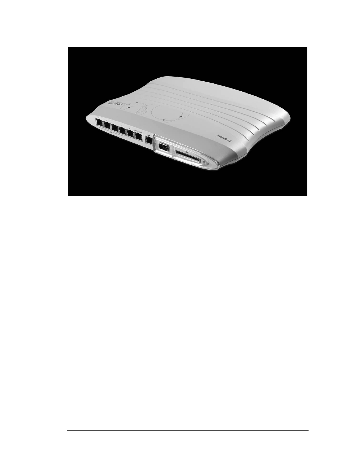
Hardware Overview
• One WAN (RJ-45) port for connection to a DSL modem, cable modem, or any other
Layer 2/3 network device.
• Six 10/100 Mbit/sec. LAN (RJ-45) ports: four ports provide 802.3af “Power over
Ethernet” (PoE) support; the other two do not provide power.
• Each port has two LEDs, one indicating the speed of the transmission (10 or 100
Mbit/sec.), the other indicating whether there is activity on the port. The four LAN ports
with PoE have a third LED that indicates whether power is being delivered over the line
to a power device (such as an Access Port). (See the WS 2000 Wireless Switch LED
explanation for more information on the meaning of the different state of the LEDs.)
• A DB-9 serial port for direct access to the command-line interface from a PC. Use
Symbol’s Null-Modem cable (Part No. 25-632878-0) for the best fitting connection.
• A CompactFlash slot that provides AirBeam™ support.
Technical Specifications
Physical Specifications
• Width: 203 mm
• Height: 38 mm
• Depth: 286 mm
• Weight: 0.64 kg
Copyright © 2004 Symbol Technologies, Inc. All Rights Reserved 8
WS 2000 Wireless Switch: 1.0 Date of last Revision: March 2004
Page 9

Power Specifications
• Maximum Power Consumption: 90-256 VAC, 47-63 Hz, 3A
• Operating Voltage: 48 VDC
• Operating Current: 1A
• Peak Current: 1.6A
Environmental Specifications
• Operating Temperature: 0ºC to 40ºC
• Storage Temperature: -40ºC to 70ºC
• Operating Humidity: 10% to 85% Non-condensing
• Storage Humidity: 10% to 85% Non-condensing
• Operating Altitude: 2.4 km
• Storage Altitude: 4.6 km
Software Overview
Software Overview
The WS 2000 Wireless Switch software provides a fully integrated solution for managing
every aspect of connecting Wireless LANs (WLANs) to a wired network, and includes the
following components:
Operating System (OS) Services
OS Services determine how the WS 2000 Wireless Switch communicates with existing
network and operating system-centric software services, including:
• Dynamic Host Configuration Protocol (DHCP)
• Telnet and File Transfer Protocol (FTP/TFTP) servers
• The Simple Network Time Protocol (SNTP) client, used to keep switch time
synchronized for Kerberos authentication
Cell Controller Services
The Cell Controller provides the ongoing communication between mobile units (MUs) on
the Wireless LAN (WLAN) and the wired network. Cell Controller services perform the
following:
• Initialize the Access Ports
• Maintain contact with Access Ports by sending a synchronized electronic “heartbeat” at
regular intervals
• Track MUs when they roam from one location to another
• Manage security schemes based on system configuration
• Maintain system statistics
• Store policies and Access Port information
Copyright © 2004 Symbol Technologies, Inc. All Rights Reserved 9
WS 2000 Wireless Switch: 1.0 Date of last Revision: March 2004
Page 10

Gateway Services
Gateway services provide interconnectivity between the Cell Controller and the wired
network, and include the following:
• System management through a web-based Graphical User Interface (GUI) and SNMP
• 802.1x RADIUS client
• Security, including Secure Sockets Layer (SSL) and Firewall
• Network Address Translation (NAT), DHCP services, and Layer 3 Routing
Software Overview
Copyright © 2004 Symbol Technologies, Inc. All Rights Reserved 10
WS 2000 Wireless Switch: 1.0 Date of last Revision: March 2004
Page 11

Chapter 2. Features
802.11a Support
802.11 is a family of specifications for wireless local area networks (WLANs) developed by
a working group of the Institute of Electrical and Electronics Engineers (IEEE). The four
current specifications include: 802.11, 802.11a, 802.11b, and 802.11g. All four use the
Ethernet protocol and carrier sense multiple access with collision avoidance (CSMA/CA)
for path sharing, which allows a number of network users to pass packets on the network
simultaneously.
The 802.11a specification applies to wireless systems, and is used in access hubs and other
network components. 802.11a operates at radio frequencies between 5 GHz and 6 GHz,
using a modulation scheme that provides for data speeds of 6, 9, 12, 18, 22, 24, 36, 48, and
54 Mbps.
The WS 2000 Wireless Switch fully supports the 802.11a specification for association with
Symbol’s suite of compatible Access Ports and mobile units (MUs).
Specifically, the WS 2000 Wireless Switch supports the following features:
• Management frames: Part of a network packet, management frames provide hardware-
and software-specific information shared between the WS 2000 Wireless Switch,
Access Ports, and MUs to keep the network operating smoothly.
802.11a Support
• Beacon and DTIM: A uniframe (single-direction) system packet broadcast by the WS
2000 Wireless Switch to keep the network synchronized. A beacon Includes the Net_ID
(ESSID), the Access Port address, the broadcast destination addresses, a time stamp, a
DTIM (Delivery Traffic Indicator Maps) and the TIM (Traffic Indicator Message)
• Roaming Updates: Provides information to the Access Ports when an MU roams from
one Access Port to another
• Power Save Polling (PSP): Helps extend battery life by allowing the radio in an Access
Port or MU to idle when not active.
• Voice Prioritization: The WS 2000 Wireless Switch uses a combination of data
classifiers, classification groups, and network input and output policies to prioritize
voice data.
• Rate Scaling: This feature seeks to connect MUs to the WS 2000 Wireless Switch (via
Access Port) at the highest possible rate, automatically scaling to a lower rate when
network traffic demands. As signal clarity increases, speed builds to an optimal rate.
• TX power setting: Optimizes the output power for any environment.
802.11b Support
802.11 is a family of specifications for wireless local area networks (WLANs) developed by
a working group of the Institute of Electrical and Electronics Engineers (IEEE). The four
current specifications include: 802.11, 802.11a, 802.11b, and 802.11g. All four use the
Ethernet protocol and provide carrier sense multiple access with collision avoidance
(CSMA/CA) for path sharing, which allows a number of network users to pass packets on
the network simultaneously.
Copyright © 2004 Symbol Technologies, Inc. All Rights Reserved 11
WS 2000 Wireless Switch: 1.0 Date of last Revision: March 2004
Page 12

Access Ports
The 802.11b standard, also called Wi-Fi (Wireless Fidelity), is backward compatible with
802.11. 802.11b uses complimentary code keying (CCK) modulation to provide higher data
speeds (up to 11 Mbps) with less multipath-propagation interference. 802.11b operates at
the 2.4 to 2.5 GHz range.
The WS 2000 Wireless Switch fully supports the 802.11b specification for association with
Symbol’s suite of compatible Access Ports and mobile units (MUs).
Specifically, the WS 2000 Wireless Switch supports the following features:
• Management frames: Part of a network packet, management frames provide hardware-
and software-specific information shared between the WS 2000 Wireless Switch,
Access Ports, and MUs to keep the network operating smoothly.
• Beacon and DTIM: A uniframe (single-direction) system packet broadcast by the WS
2000 Wireless Switch to keep the network synchronized. A beacon Includes the Net_ID
(ESSID), the Access Port address, the Broadcast destination addresses, a time stamp, a
DTIM (Delivery Traffic Indicator Maps) and the TIM (Traffic Indicator Message).
• Roaming Updates: Provides information to the Access Ports when an MU roams from
one Access Port to another.
• Power Save Polling (PSP): Helps extend battery life by allowing the radio in an Access
Port or MU to idle when not active.
• Voice Prioritization: The WS 2000 Wireless Switch uses a combination of data
classifiers, classification groups, and network input and output policies to prioritize
voice data.
• Rate Scaling: This feature seeks to connect MUs to the WS 2000 Wireless Switch (via
Access Port) at the highest possible rate, automatically scaling to a lower rate when
network traffic demands. As signal clarity increases, speed builds to an optimal rate.
• TX power setting: Optimizes the output power for any environment.
Access Ports
Access Ports are the Symbol devices that pick up wireless transmissions and translate them
into Ethernet frames that are sent to the wireless switch for processing and routing. The
packets destined for wireless networks are sent back to the Access Ports where they are
transmitted.
Access Ports may be connected directly to the WS 2000 Wireless Switch or through a PoE
(Power over Ethernet) hub connected to the WS 2000. Up to six Access Ports can be
connected to this wireless switch.
When an Access Port is attached to a switch, it sends out a “boot me” packet as a broadcast
message. This packet specifies the hardware model of the port and its MAC address. When
the WS 2000 Wireless Switch receives a “boot me” packet, it uploads the appropriate
firmware for the Access Port. Once complete, the Access Port becomes active.
For an Access Port to be adopted by the WS 2000 Wireless Switch, three things must be
configured:
1. The Country field in the System Settings screen must be set.
2. The Access Port’s MAC address must be set as one of the addresses that can be adopted
by one of the enabled WLANs. (see Step 4)
3. A WLAN that can adopt Access Port must be associated with an enabled subnet. (see
Step 5)
Copyright © 2004 Symbol Technologies, Inc. All Rights Reserved 12
WS 2000 Wireless Switch: 1.0 Date of last Revision: March 2004
Page 13

Gateway Services
Network Address Translation (NAT)
NAT provides the translation of an Internet Protocol (IP) address within one network to a
different, known IP address within another network. One network is designated the private
network, while the other is the public. NAT provides a layer of security by translating local,
private network addresses to one or more global, public IP addresses through a corporate
firewall. The translation process provides an opportunity to authenticate outgoing or
incoming requests or match these requests to a previous request. NAT allows a company to
use a single IP address to communicate with the Internet community.
The WS 2000 Wireless Switch provides service, or forward, and reverse NAT translation on
packets to and from the WAN and is fully compliant with RFC 1631.
WS 2000 Wireless provides network administrators with the following implementation
options:
• Mapping up to 8 public IP addresses to private IP address ranges.
• Client IP addresses on the private side have IP addresses translated to ports or IP
addresses on the WAN. Administrators can configure connections to originate from
either end.
Gateway Services
• One-to-one mapping with a private IP address or a range of private IP addresses.
• Private side IP address can belong to any of the private side subnets.
• Ranges can be specified from each of the private side subnets.
WS 2000 Wireless Switch Firewall
The firewall includes a proprietary CyberDefense Engine to protect internal networks from
known Internet attacks, including FTP Bounce, MIME Flood, IP Spoofing, Land Attack,
Ping of Death, Reassembly, SYN Flooding, and Winnuke. It also provides additional
protection by performing the following checks: source routing, IP unaligned timestamp, and
sequence number prediction.
Firewall features include:
Stateful Inspection Engine
The firewall inspects incoming packets based on security policies before processing them in
higher-level protocols. This feature significantly boosts performance, as packets do not
require copying from the operating system to user space for inspection.
Access Policies
Access policies define how network services, including source and destination IP addresses,
range or subnet IP address, ports, and access time windows, work. Administrators organize
the user community in different user groups and define access policies on per user group
basis.
Administration Management
Administrators change access policies locally or remotely, using the web-based user
interface (UI) or by modifying text-based configuration files.
Copyright © 2004 Symbol Technologies, Inc. All Rights Reserved 13
WS 2000 Wireless Switch: 1.0 Date of last Revision: March 2004
Page 14

DHCP Client and Server
The WS 2000 Wireless Switch can act as a DHCP client on the WAN and each of its three
subnets. It also act as an independent DHCP server on each of the three subnets.
Layer 3 Routing
Overview
The WS 2000 Wireless Switch provides Layer 3 routing support to the Network Address
Translation (NAT) and Firewall modules. Layer 3 refers to a network layer that selects
routes and quality of service based on knowing the address of the neighboring nodes in the
network. This routing provides recognition and forwards incoming messages to the
Transport layer for local host domains.
Routing Information Protocol (RIP) Support
Layer 3 supports RIP, a widely used protocol for managing router information within a selfcontained network or a group of networked LANs.
Using RIP, the WS 2000 Wireless Switch sends a routing table with information containing
all the hosts it is configured to identify to the closest LAN host. The LAN host passes the
information on to the next closest LAN host until all hosts within the network have the
same knowledge of routing paths, a condition referred to as network convergence. Network
components distribute routing table information at preset intervals to maintain convergence.
To route a packet to a specified destination, each host with a router in the network uses the
routing table information to determine the destination host location.
Layer 3 Routing
SNMP Management Support
Simple Network Management Protocol (SNMP) is the protocol governing network
management and the monitoring of network devices and their functions. SNMP defines the
method for obtaining information about network operating characteristics and lets
administrators change parameters for routers and gateways.
SNMP uses the Management Information Base (MIB), or formal description of a set of
network objects that represent the switch components, to facilitate network management in
any wireless network environment.
SNMP management features include:
• Allowing gets, or the ability to retrieve data from a remote host given its host name and
authentication information
• Allowing sets, or the ability to modify information on a remote host
• A web-based user interface (UI) for viewing traps, which network entities use to signal
abnormal conditions to management stations. Administrators define trap conditions in
the MIB.
The WS 2000 Wireless Switch provides management support for SNMP versions 1, 2, and
3.
Copyright © 2004 Symbol Technologies, Inc. All Rights Reserved 14
WS 2000 Wireless Switch: 1.0 Date of last Revision: March 2004
Page 15

WEP 64 (40-bit key)
Wired Equivalency Privacy (WEP) uses a key, or string of case-sensitive characters, to
encrypt and decrypt data packets transmitted between a mobile unit (MU) and the WS 2000
Wireless Switch. The administrator configures mobile units (MUs) and the WS 2000
Wireless Switch to use the same key.
WEP encrypts the wireless transmissions, but still allows communication among compatible
wireless LAN clients and MUs from third-party manufacturers that are 802.11b certified.
40-bit Shared Key requires encryption be set up in one of the following ways:
• String: For use only with other Symbol Technologies wireless LAN devices, an
encryption string is a case-sensitive string of characters between 6 and 30 characters
long.
• Shared keys: Hexadecimal keys are sequences of hexadecimal digits arranged into four
keys. A hexadecimal digit could be a letter from A to F or a number from 0 to 9. This
type of encryption is compatible with equipment from other manufacturers that use WiFi certified 40-bit encryption.
WEP 128 (104-bit Key)
Wired Equivalency Privacy (WEP) uses a key, or string of case-sensitive characters, to
encrypt and decrypt data packets transmitted between a mobile unit (MU) and the WS 2000
Wireless Switch. The administrator configures the MU and switch to use the same key. 104bit Shared Key provides a higher level of security than the 40-bit Shared Key option and
uses a more complicated encryption scheme.
WEP 64 (40-bit key)
WEP encrypts the wireless transmissions, but still allows communication among compatible
wireless LAN clients and MUs from third-party manufacturers that are 802.11b certified.
WEP 128 requires encryption be set up in one of the following ways:
• String: For use only with other Symbol Technologies wireless LAN devices, an
encryption string is a case-sensitive string of characters between 6 and 30 characters
long.
• Shared keys: Hexadecimal keys are sequences of hexadecimal digits arranged into four
keys. A hexadecimal digit could be a letter from A to F or a number from 0 to 9.
802.1x with RADIUS Authentication
RADIUS is a client/server protocol and software that enables remote access servers to
communicate with a central server to authenticate RADIUS-enabled mobile units (MUs)
and authorize their access to the requested system or service.
When an MU authenticates with a WS 2000 Wireless Switch through an Access Port, the
switch initially performs RADIUS authentication, even though the RADIUS server exists as
a separate entity on the wired LAN. This RADIUS server maintains user profiles in a
central database that all remote servers can share. This centralized location provides better
security by using a policy-based implementation through a single administered network
point.
The RADIUS server on the wired LAN communicates with the WS 2000 Wireless Switch
RADIUS client, passing authentication information from the MU. A successful negotiation
authenticates the MU.
Copyright © 2004 Symbol Technologies, Inc. All Rights Reserved 15
WS 2000 Wireless Switch: 1.0 Date of last Revision: March 2004
Page 16

802.1x with Shared Key Authentication
The pair-wise master keys (PMK) generated by this negotiation are used to generate keys
used in MAC encryption. In the absence of a RADIUS server, 802.1x is used in a preshared key configuration. Administrators configure the master key statically through the
configuration or the key is obtained through negotiation from an external RADIUS server in
compliance with 802.1x.
The WS 2000 Wireless Switch uses the Remote Authentication Dial-In User Service
(RADIUS) to authenticate 802.1x-enabled MUs.
802.1x with Shared Key Authentication
Shared key authentication, part of the Wired Equivalency Privacy (WEP) algorithm,
provides a basic means of data encryption to improve data security for a Wireless LAN
(WLAN). The shared key algorithm performs data encryption and decryption. A wireless
device with a valid shared key is allowed to associate with the WS 2000 Wireless Switch
and access services on the wired LAN.
Using shared key authentication, an administrator configures mobile units (MUs) and the
WS 2000 Wireless Switch to share the same key. The MU authenticates by presenting the
key to a WS 2000 Wireless Switch. The switch examines the key, and uses it to perform a
checksum, or error-checking operation, by comparing the key to one on the switch. The MU
accesses network services only when the key passes the checksum process.
The WS 2000 Wireless Switch uses shared key authentication when there is no RADIUS
server on the wired LAN.
Kerberos Authentication
The Kerberos authentication service protocol (specified in RFC 1510) provides a secure
means for authenticating users/clients in a wireless network environment.
With Kerberos, a client (generally either a user, a service, or a user requesting any number
of network services) within the Kerberos Realm sends a request for a ticket to the Key
Distribution Center (KDC). The KDC creates a ticket-granting ticket (TGT) for the client,
encrypts it using the Ticket Granting Server’s (TGS) secret key, and sends the encrypted
TGT back to the client. In addition to the TGT, the KDC simultaneously sends a session
key (SK1) encrypted with the client’s password to the client. The client then attempts to
decrypt the session key using its password. If the client successfully decrypts the session
key (i.e., if the client gave the correct password), it keeps the decrypted session key, which
indicates proof of the client’s identity. The TGT permits the client to obtain additional
tickets (TK-TS) which give permission for specific network services (any application or
service) for the allotted time identified in the TK-TS. The requesting and granting of these
additional tickets is user-transparent. Once the session tickets expire, the client must reauthenticate to continue using network services.
The KDC operates in a Master or a Slave capacity. The Master KDC maintains the master
database file that contains all of the user authentication information. This information
includes the user’s name, password, and authorization level. This authorization level
determines what network services the user has access to.
The Slave KDC acts in a backup capacity to the Master KDC. Database information
propagates from the Master KDC to the Slave at regular intervals. If the Master KDC fails,
the Slave KDC resumes ticket granting services until the problem causing the Master KDC
to fail is resolved. The Slave KDC has no database administration privileges, which are
reserved for the Master KDC.
Copyright © 2004 Symbol Technologies, Inc. All Rights Reserved 16
WS 2000 Wireless Switch: 1.0 Date of last Revision: March 2004
Page 17

When a Kerberos-enabled mobile unit (MU) authenticates with WS 2000 Wireless through
an Access Port, the switch initially performs Kerberos authentication, even though the
Kerberos server exists as a separate entity on the wired LAN. On initial request from a
Kerberos-enabled MU, the WS 2000 Wireless Switch acts as a proxy to the external KDC.
The switch passes initial Kerberos authentication information to the external KDC until the
MU authenticates in the manner described in this section. Once authenticated, the user
maintains access to the wired network for the allotted time provided by the session ticket
(TK-TS).
Once an administrator enables Kerberos on a device, the device must pass authentication
before wireless access via the device is permitted to the wired LAN.
KeyGuard-MCM Support
KeyGuard-MCM (Mobile Computing Mode) is Symbol Technologies’ security
enhancement algorithm based on the Temporal Key Integrity Protocol (TKIP) from the
forthcoming IEEE 802.11i standard. KeyGuard-MCM provides an enhanced solution for
protecting data transfer over a Wireless LAN (WLAN) by using a proprietary algorithm to
encrypt, decrypt, and transmit network packets.
KeyGuard-MCM leverages existing WEP encryption hardware by providing per-packet key
mixing, a message integrity check, and a re-keying mechanism, which changes the security
key set by the administrator when KeyGuard-MCM recognizes a potential compromise of
network security.
KeyGuard-MCM Support
KeyGuard-MCM works with all Symbol Technologies’ mobile units that support 128-bit
WEP. KeyGuard-MCM is fully compatible with other network security protocols, including
RADIUS and Kerberos.
The WS 2000 Wireless Switch fully supports KeyGuard-MCM.
Wireless Protected Access (WPA)
WEP uses a key, or string of case-sensitive characters, to encrypt and decrypt data packets
transmitted between a mobile unit (MU) and the WS 2000 Wireless Switch. The
administrator configures mobile units (MUs) and the WS 2000 Wireless Switch to use the
same key.
WPA specifies the use of the TKIP, and optionally, 802.1x for encryption.
Copyright © 2004 Symbol Technologies, Inc. All Rights Reserved 17
WS 2000 Wireless Switch: 1.0 Date of last Revision: March 2004
Page 18

Chapter 3. Getting Started
Getting Started Overview
Installing the Switch
To install the WS 2000 Wireless Switch hardware, follow the directions in the WS 2000
Wireless Switch Quick Installation Guide found in the box with the switch and on the CD-
ROM that is distributed with the switch. These instructions describe how to:
• Select a site (desk, wall, or rack) for the switch
• Install the switch using the appropriate accessories for the selected location
• Connect devices to WAN and LAN ports (using standard CAT5 cables)
• Interpret the port LEDs on the front of the switch
Note: Access Ports must be connected to the LAN ports of the wireless
switch to enable configuration of the Access Port related settings.
Set up Communication to the Switch
Getting Started Overview
Before the configuration process can begin, a link with the wireless switch needs to be
established:
1. Connect a computer to the switch (in any one of the LAN ports) using a standard CAT5
cable.
2. Set up the computer for TCP/IP DHCP network addressing.
3. Start up Internet Explorer (with Microsoft’s Java Virtual Machine installed) and type in
the following IP address in the address field: 192.168.0.1
Note: For optimum compatibility use Microsoft’s Java Virtual Machine,
and be sure to disable the Sun Microsystems’ JRE. If Microsoft’s Java
Virtual Machine is unavailable, please use Sun Microsystems’ JRE
version 1.3 for best.
The following screen is displayed.
Copyright © 2004 Symbol Technologies, Inc. All Rights Reserved 18
WS 2000 Wireless Switch: 1.0 Date of last Revision: March 2004
Page 19
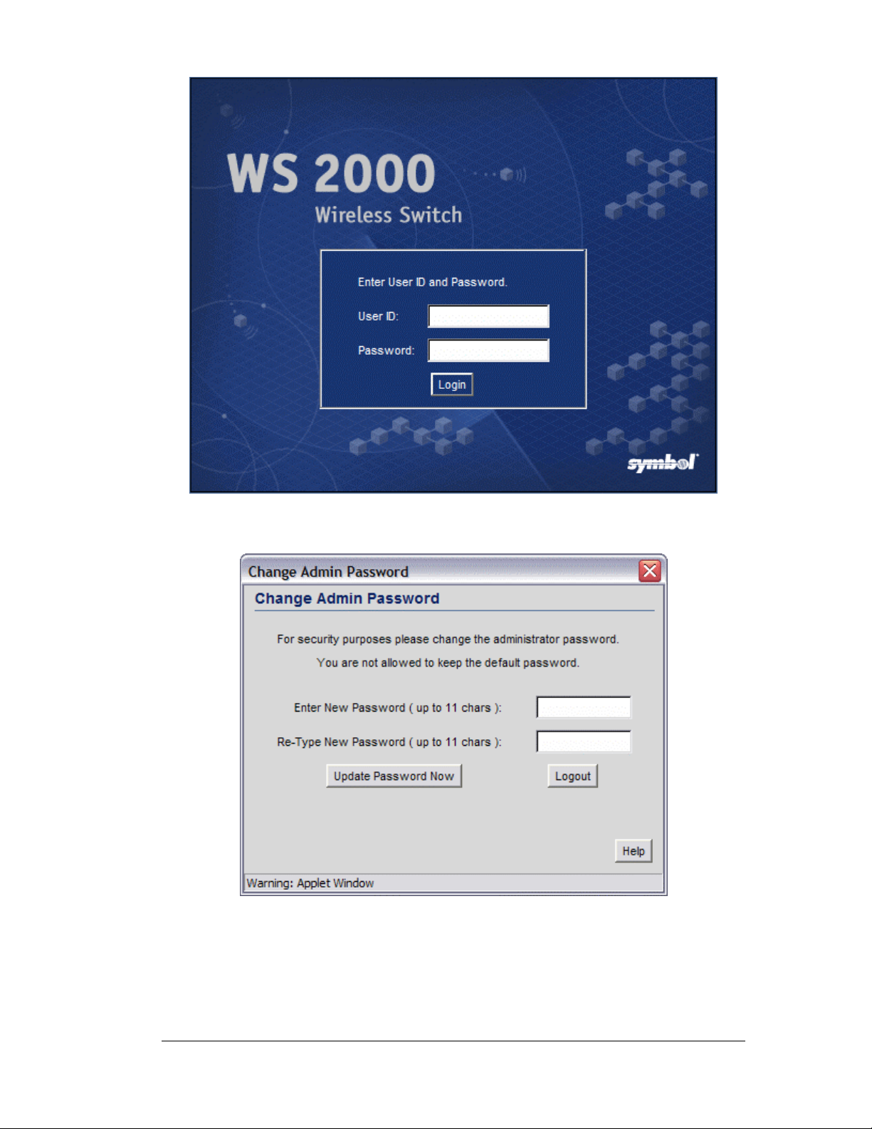
Getting Started Overview
4. Log in using “admin” as the username and “symbol” as the password.
5. If the login is successful, the following prompt will be displayed.
Enter a new admin password in both fields, and click the Update Password Now
button.
6. Once the admin password has been updated, the System Settings screen is displayed.
Copyright © 2004 Symbol Technologies, Inc. All Rights Reserved 19
WS 2000 Wireless Switch: 1.0 Date of last Revision: March 2004
Page 20
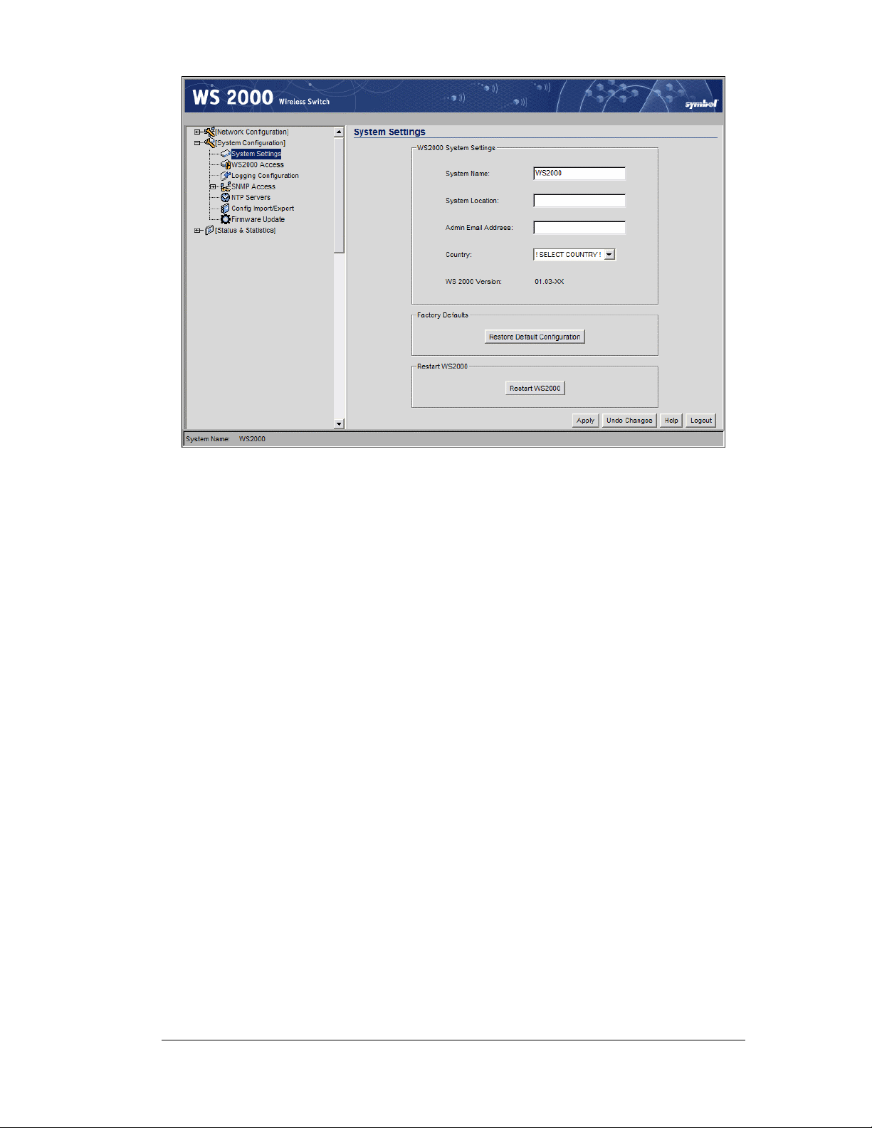
Getting Started Overview
7. Enter a System Name for the wireless switch. The specified name appears in the
lower-left corner of the configuration screens, beneath the navigation tree. This name
can be a useful reminder if multiple Symbol wireless switches are installed.
8. Enter a text description of the location of the switch in the System Location field.
This text is used as a reminder to the network administrator and is also used to set the
location variable if the switch is administered using SNMP.
9. Enter an email address for the administrator in the Admin Email Address field. The
switch will use this address for sending SNMP-related and other administration-related
messages to the administrator.
10. Select the Country for the switch from the drop-down menu. Selecting the correct
country is extremely important. Each country has its own regulatory restrictions
concerning electromagnetic emissions and the maximum RF signal strength that can be
transmitted by Access Ports. To ensure compliance with national and local laws, be sure
to set this field accurately.
11. Click Apply to save changes. Unapplied changes are lost if the administrator navigates
to a different screen.
Changing the Administrator Password
The password information set at the factory is the same for all WS 2000 Network Switches.
For security reasons, it is important to change the switch’s admin password as soon as
possible.
1. Select System Configuration --> WS-2000 Access from the left menu.
2. Click the Change Admin Password button. A sub-screen will appear.
3. Enter the current admin password (“symbol” if it hasn’t been changed previously), as
well as a new password (limited to 11 characters in length). Enter the new password a
second time in the field provided.
4. Click Update Password Now to set the new password.
Copyright © 2004 Symbol Technologies, Inc. All Rights Reserved 20
WS 2000 Wireless Switch: 1.0 Date of last Revision: March 2004
Page 21

Configuring the Switch
Once the switch is installed, perform the rest of the basic configuration and setup process as
indicated in the following procedures. The links go to pages that have detailed information
about the particular configuration step. The left menu item associated with each procedure
is specified to the right of the link
• Step 1: Configure the LAN interface and enable subnets (Network Configuration -->
LAN in the left menu)·
• Step 2: Configure subnets (Network Configuration --> LAN --> Subnet)
• Step 3: Configure the WAN Interface (Network Configuration --> WAN)
• Step 4: Enable Wireless LANs (WLANs) (Network Configuration --> Wireless)
• Step 5: Configure WLANs (Network Configuration --> <WLAN name>)
• Step 6: Configure WLAN Security (Network Configuration --> <WLAN name> -->
Security)
• Step 7: Configure Access Ports (Network Configuration --> Access Ports -->
<Access Port Name>)
• Step 8: Configure subnet access (Network Configuration --> Subnet Access)
The following advanced setup tasks are optional:
Step 1: Configure the LAN Interface
• Set up the firewall configuration (Network Configuration --> WAN --> Firewall)
• Set up Network Address Translation (NAT) (Network Configuration --> WAN -->
NAT)
• Set up static routing (Network Configuration --> Router) Refer to the two case
studies provided with this reference for specific installation examples.
These case studies describe the environment, the desired features, and the configuration
selections that were made in two different scenarios.
• Case 1: Small Retail Store (with handheld terminals, wireless printers, wired POS,
secured access to in-store server, and public access to WAN)·
• Case 2: Small Branch Office (with 3 WAN IP addresses, VPN passthrough, RADIUS
server, and full-access between subnets)
Proceed to: Step 1: Configure the LAN Interface
Step 1: Configure the LAN Interface
The first step of the network configuration process is to figure out the topology of the LAN.
The WS 2000 Wireless Switch allows the administrator to enable and configure three
different subnets. The administrator can assign a IP address, port associations, DHCP
settings, and security settings to each subnet.
This System Reference provides two case studies that demonstrate how requirements for
network access and capabilities drive the decisions of how to configure the subnets.
Copyright © 2004 Symbol Technologies, Inc. All Rights Reserved 21
WS 2000 Wireless Switch: 1.0 Date of last Revision: March 2004
Page 22
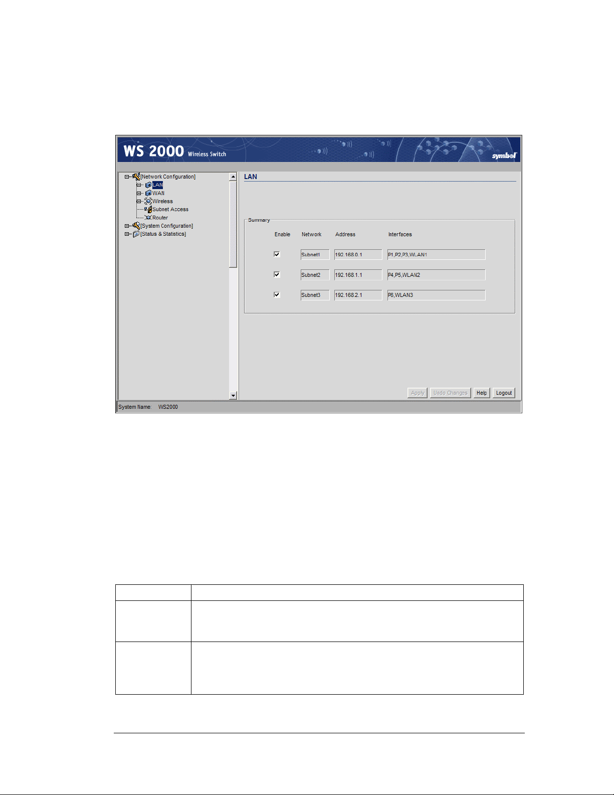
Defining the Subnets
Select LAN under the Network Configuration group from the left menu. Use the LAN
configuration screen to view a summary of physical-port addresses and Wireless LANs
(WLANs) associated with the three supported subnets, and to enable or disable each
configured subnet.
Step 1: Configure the LAN Interface
1. In the LAN screen, the administrator can enable one, two or three subnets. Check the
checkbox to the left of the subnet to enable a subnet. Up to three subnets can be enabled
to use the wired and/or wireless connections of the switch-managed LAN. Enable
multiple subnets to divide the communications of different business areas or operations.
Each enabled subnet shows up in the directory tree in the left column of the
configuration screens. Consider disabling a previously configured subnet if its assigned
ports are no longer in use, or to consolidate the LAN’s communications on fewer
subnets.
2. Click Apply to save changes—all “unapplied” changes are lost when the administrator
moves to a new screen. The rest of the information on this screen is summary
information— it is collected from other screens (such as the subnet configuration
screens) where the administrator can set the data.
Field Description
Network
Address
Network (subnet) name is a descriptive string that should describe the
subnet’s function. The WS 2000 Network Management System uses
subnet names throughout the configurations screens.
This IP address allows users from outside the subnet (whether from
the WAN or from another subnet from the same switch) to access the
right subnet. An IP address uses a series of four numbers that are
expressed in dot notation, for example, 194.182.1.1.
Copyright © 2004 Symbol Technologies, Inc. All Rights Reserved 22
WS 2000 Wireless Switch: 1.0 Date of last Revision: March 2004
Page 23
Field Description
Interfaces
The Interfaces field displays which of the six physical LAN ports are
associated with the subnet. The possible ports are: P1 (port 1), P2,
P3, P4, P5, and P6 (from left to right facing the front of the switch).
The administrator assigns a port to a subnet to enable access to the
device(s) connected to that port. The administrator can assign a port
to only one subnet.
The Interfaces field also lists the WLANs that are associated with the
subnet.
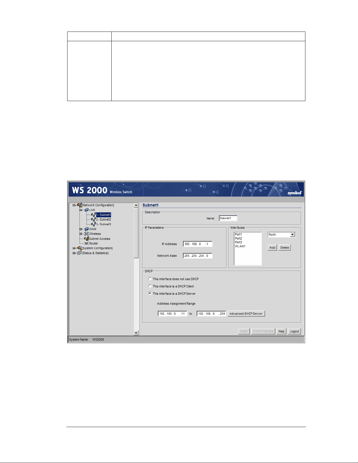
Step 2: Configure Subnets
The WS 2000 Network Management System allows the administrator to define and refine
the configuration of the enabled subnets. Each of three subnets (short for “subnetworks”)
can be configured as an identifiably separate part of the switch-managed Local Area
Network (LAN). Each subnet can include some combination of assigned ports and
associated Wireless LANs (WLANs).To configure an enabled subnet, select the subnet
name from the Network Configuration --> LAN list in the left. The following screen
will appear for the selected subnet.
Step 2: Configure Subnets
1. Change the Name of the subnet to use a descriptive name that indicates something
about the subnet. The name can contain seven characters, including spaces and
numbers. It will appear in the left menu under the LAN menu item.
2. Set an IP address to be used for the subnet. This is how the switch will refer
specifically to this subnet. This could be a WAN address; but more likely it will be a
non-routable address. An IP address uses a series of four numbers that are expressed in
dot notation, for example, 194.182.1.1.
Copyright © 2004 Symbol Technologies, Inc. All Rights Reserved 23
WS 2000 Wireless Switch: 1.0 Date of last Revision: March 2004
Page 24

3. Set the Network Mask for the IP address. A network mask uses a series of four
numbers that are expressed in dot notation, similar to an IP number. For example,
255.255.255.0 is a network mask.
Select a port or WLAN from the Interfaces drop-down menu to associate it with the
subnet. Six LAN ports are available on the switch. Assign from one to six ports to a
subnet. Two subnets cannot use the same port. However, multiple ports can be assigned
to one subnet.
Three WLANs are available. WLAN assignments are logical designations. Associate
from zero to three WLANs with a subnet. Two subnets cannot use the same WLAN.
However, multiple WLANs can be associated with one subnet. If two or three WLANs
are associated with one subnet, each port dedicated to that subnet can use any of the
associated WLANs.
4. Click on the Add button to add it to the Interfaces list.
Note that wireless devices cannot access the switch unless a WLAN is
configured and associated with a subnet. (This process is described in
Configuring the Wireless LAN.)
The DHCP Configuration
DHCP is a protocol that includes mechanisms for IP address allocation and delivery of hostspecific configuration parameters from a DHCP server to a host. Some of these parameters
are IP address, network mask, and gateway. The switch includes internal DHCP server and
client features, and the subnet’s interface can use either capability.
Step 2: Configure Subnets
1. Click the appropriate radio button to select one DHCP setting for the subnet’s
interfaces:
• Select This interface does not use DHCP to disable DHCP on this subnet and
specify IP addresses manually.
• Select This interface is a DHCP Client if this subnet obtains IP parameters
from a DHCP server outside the switch.
• Select This interface is a DHCP Server to enable the switch’s DHCP server
features.
2. If This interface is a DHCP Server is the selected option, fill in the Address
Assignment Range fields. These fields allow the administrator to assign a range of
IP addresses to devices as they connect.
3. Set the Advanced Settings, if necessary.
4. Click the Apply button to save all changes.
Copyright © 2004 Symbol Technologies, Inc. All Rights Reserved 24
WS 2000 Wireless Switch: 1.0 Date of last Revision: March 2004
Page 25
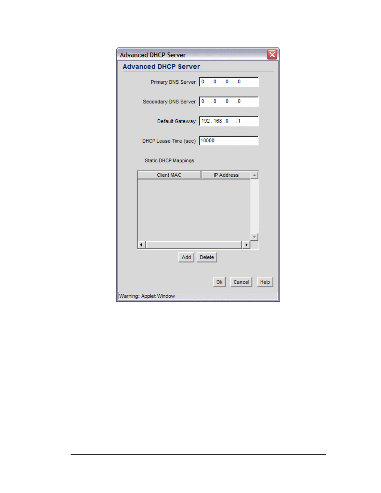
Advanced DHCP Settings
Step 2: Configure Subnets
1. Click the Advanced DHCP Server button to display a sub-screen to further
customize IP address allocation (on right).
2. Specify the address of a Primary DNS server. The Internet Server Provider (ISP) or a
network administrator can provide this address. A DNS server translates a domain
name, such as www.symbol.com, into an IP address that networks can use.
3. Specify the address of a Secondary DNS server if one is available.
4. Specify a DHCP Lease Time period in seconds for available IP addresses. The DHCP
server grants an IP address for as long as it remains in active use. The lease time is the
number of seconds that an IP address is reserved for re-connection after its last use.
Using very short leases, DHCP can dynamically reconfigure networks in which there
are more computers than there are available IP addresses. This is useful, for example, in
education and customer environments where mobile-unit users change frequently. Use
longer leases if there are fewer users.
Copyright © 2004 Symbol Technologies, Inc. All Rights Reserved 25
WS 2000 Wireless Switch: 1.0 Date of last Revision: March 2004
Page 26
5. Use the Static Mappings table to associate static (or fixed) IP addresses with MAC
addresses of specific wireless devices. Every wireless, 802.11x-standard device has a
unique Media Access Control (MAC) address. This address is the device’s hard-coded
hardware number (shown on the bottom or back). An example of a MAC address is
00:09:5B:45:9B:07.
This MAC table of specified devices provides corresponding static IP addresses for
users, mobile units, and applications that may prefer or require such access.
Step 3: Configure the WAN Interface
A Wide Area Network (WAN) is a widely dispersed telecommunications network. In a
corporate environment, the WAN port might connect to a larger corporate network. For a
small business, the WAN port might connect to a DSL or cable modem to access the
Internet.
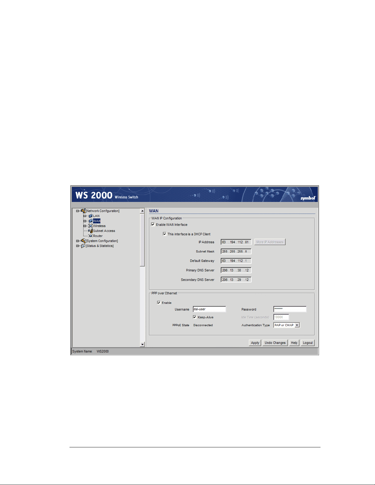
The administrator needs to enter the WAN configuration information. The WS 2000
Wireless Switch includes one WAN port. In order to set up communications with the
outside world, select Network Configuration --> WAN from the left menu. The
following WAN configuration page appears.
Step 3: Configure the WAN Interface
Communicating with the Outside World
1. Use the Enable WAN Interface checkbox to enable a connection between the switch
and a larger network or the outside world through the WAN port, check the Enable
WAN Interface checkbox.
2. Check This interface is a DHCP Client checkbox to enable Dynamic Host
Configuration Protocol (DHCP) for the WAN connection. If This interface is DHCP
Client is checked, the switch is limited to one WAN IP address. This choice is required
when:
Copyright © 2004 Symbol Technologies, Inc. All Rights Reserved 26
WS 2000 Wireless Switch: 1.0 Date of last Revision: March 2004
Page 27

Step 3: Configure the WAN Interface
• The host router or switch on the WAN is communicating with the WS 2000
Wireless Switch using DHCP.
• The switch is interfacing with an Internet Service Provider (ISP) that uses DHCP
addressing.
Note: This setting is independent from the DHCP settings for the switch’s
internal subnets.
3. It is not necessary to specify the IP Address or any of the other fields on the top section
of this form when the WS 2000 wireless switch is set as a DHCP Client. The network
host (router, switch, or modem) will provide these values each time it makes a
connection with the wireless switch.
4. If the DHCP setting is not checked, fill in the information in this area. To find out the
information to enter into these fields, contact the network administrator or the ISP that
provided the cable modem or DSL router. All the fields below take standard IP
addresses of the form xxx.xxx.xxx.xxx.
• The IP Address refers to the IP address that the outside world will use to address
the WS 2000 Wireless Switch.
• Click the More IP Addresses button to specify additional static IP addresses for
the switch. Additional IP addresses are required when users within the LAN need
dedicated IP addresses, or when servers in the LAN need to be accessed (addressed)
by the outside world. The pop-up window allows the administrator to enter up to
eight WAN IP addresses for the switch.
• The Subnet Mask is the mask used for the WAN.
• The Default Gateway is the address of the device that provides the connection to
the WAN (often a cable modem or DSL router).
• The two DNS Server fields specify DNS addresses of servers that can translate
domain names, such as www.symbol.com, into IP addresses that the network uses
when passing information. The Secondary DNS Server acts as a backup to the
Primary DNS Server, when the primary server is not responding.
Setting Up Point-to-Point over Ethernet (PPPoE) Communication
PPPoE provides the ability to connect a network of hosts through a simple device to a
remote access concentrator. Many DSL providers require that their clients communicate
using this protocol. The facility allows the ISP to control access, billing, and type of service
provided to clients on a per-user or per-site basis. Check with the network administrator or
ISP to determine whether to enable this feature, and, if so, find out the username and
password required for authentication.
1. Check Enable in the PPP over Ethernet area to enable the PPPoE protocol for high-
speed connections.
2. Enter the Username and Password required for authentication. The username and
password is for the switch’s router to use when connecting to the ISP. When the
Internet session starts, the ISP authenticates the username.
3. Set the Idle Time to an appropriate number. This number is the amount of time the
PPPoE connection will be idle before it disconnects. The 10000 second (default idle
time) is appropriate for most situations.
Copyright © 2004 Symbol Technologies, Inc. All Rights Reserved 27
WS 2000 Wireless Switch: 1.0 Date of last Revision: March 2004
Page 28

Step 4: Enable Wireless LANs (WLANs)
4. Check Keep Alive to instruct the switch to continue occasional communications over
the WAN even when client communications to the WAN are idle. Some ISPs terminate
inactive connections, while others do not. In either case, enabling Keep-Alive mode
keeps the switch’s WAN connection alive, even when there is no traffic. If the ISP
drops the connection after so much idle time, the switch automatically reestablishes the
connection to the ISP.
5. Select the appropriate WAN authentication method from the drop-down menu. Collect
this information from the network administrator. Select between None, PAP, CHAP,
or PAP or CHAP.
CHAP
PAP
A type of authentication in which the person logging in uses secret
information and some special mathematical operations to come up with a
number value. The server he or she is logging into knows the same secret
value and performs the same mathematical operations. If the results match,
the person is authorized to access the server. One of the numbers in the
mathematical operation is changed after every log-in, to protect against an
intruder secretly copying a valid authentication session and replaying it later
to log in.
An identity verification method used to send a user name and password over
a network to a computer that compares the user name and password to a
table listing authorized users. This method of authentication is less secure,
because the user name and password travel as clear text that a hacker could
read.
6. Click the Apply button to save changes.
Step 4: Enable Wireless LANs (WLANs)
The WS 2000 Wireless Switch works either in a wired or wireless environment; however,
the power of the switch is associated with its support of wireless networks. In order to use
the wireless features of the switch, the administrator needs to enable one, two or three
wireless LANs (WLANs).
To start the WLAN configuration process, select the Network Configuration -->
Wireless item from the left menu. The following Wireless summary screen appears.
Copyright © 2004 Symbol Technologies, Inc. All Rights Reserved 28
WS 2000 Wireless Switch: 1.0 Date of last Revision: March 2004
Page 29
Step 4: Enable Wireless LANs (WLANs)
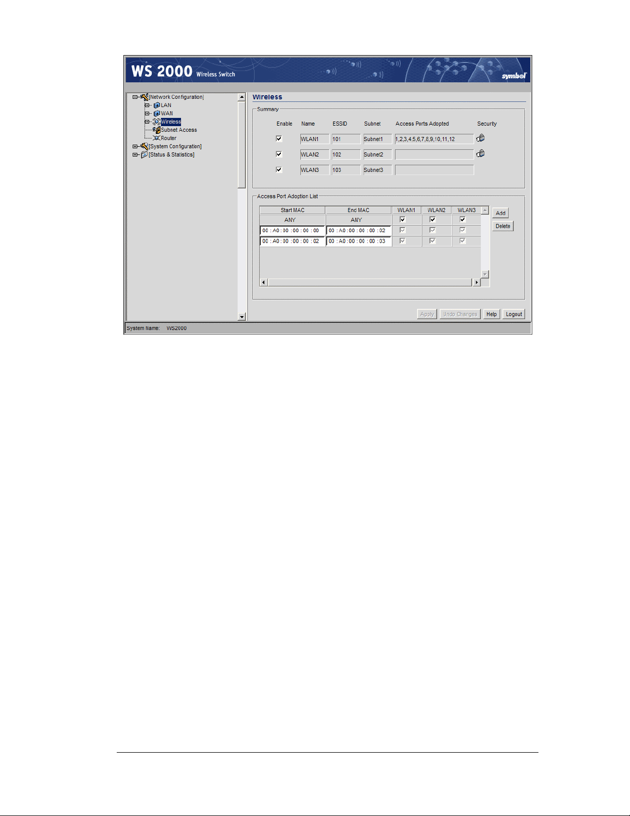
Wireless Summary Area
The top portion of the window displays a summary of the WLANs that are currently
defined. This is the screen in which the administrator can enable or disable a WLAN. At
first, three WLANs will be listed WLAN1, WLAN2, and WLAN3; however, only WLAN1
will be enabled.
1. To enable either WLAN2 or WLAN3 check the appropriate checkboxes to the left of
the WLAN name. When the administrator enables one of the WLANs, the name of an
enabled WLAN shows up as an item on the list of WLANs that reside under Wireless
in the left menu (after clicking the Apply button). When an administrator disables a
WLAN, it disappears from the menu tree. A WLAN cannot be fully configured unless it
is enabled.
2. Assign the enabled WLANs descriptive names. The administrator can change the
Name of any of the WLANs in this field. This change will affect several other screens
and the interface will change the name in the left menu tree.
3. By default, the switch assigns consecutive Extended Service Set Identification
(ESSIDs). This is the name that users will see when accessing the wireless network.
The ESSID can be given any recognizable alphanumeric string up to 32 characters in
length.
4. An icon of a lock will appear under the Security heading if any wireless encryption or
authentication is enabled for the WLAN.
The current settings for the associated Subnet and adopted Access Ports are also displayed
on this screen; however, the screen associated with each WLAN (under Network
Configuration --> Wireless) is where the settings and rules for adopting Access Ports
can be modified.
Copyright © 2004 Symbol Technologies, Inc. All Rights Reserved 29
WS 2000 Wireless Switch: 1.0 Date of last Revision: March 2004
Page 30

Access Port Adoption
Use this list to adopt detected Access Ports and to assign them to a particular WLAN. The
switch can adopt up to six Access Ports at a time, but the list of allowed Access-Port
addresses (displayed in this area) can exceed six in number. A dual-radio 802.11a/b Access
Port counts as one Access Port with respect to the maximum allowed; however, each radio
will be listed as a separate Access Port.
This adoption list identifies each Access Port by its Media Access Control (MAC) address.
This address is the Access Port’s hard-coded hardware number that is printed on the bottom
of the device. An example of a MAC address is 00:09:5B:45:9B:07.
1. To adopt an access port, click the Add button to add a new criteria line to the table.
2. Specify the following fields:
Field Description
Start MAC
This field contains the lowest value in a range of MAC addresses that
will use this particular adoption criteria. To specify a single MAC
address instead of a range, enter it in this field and leave the End
MAC field blank.
Step 5: Configure WLANs
End MAC
WLAN
columns
This field contains that highest number in a range of MAC addresses
that will use this particular adoption criteria. If this value is empty, the
Access Port adopted by this criteria must match the Start MAC field
exactly.
The next one to three columns have the same names as the WLANs
that are enabled in the upper portion of the screen. Click on the
checkbox for a specific WLAN to associate the Access Ports that
match the MAC address range with the checked WLANs.
Note: The default setting for the switch has both the Start MAC and End
MAC addresses set to “ANY”, and all enabled WLANs checked. This
setting allows all the WLANs to adopt any Access Port that it detects,
automatically.
3. Click the Apply button to save changes.
Step 5: Configure WLANs
The Network Configuration --> Wireless window (covered in Step 4) is where
WLANs are enabled; however, the Network Configuration --> Wireless --> <WLAN
name> screen is where the administrator configures each WLAN, once it is enabled. The
screen is titled with the name of the WLAN.
Copyright © 2004 Symbol Technologies, Inc. All Rights Reserved 30
WS 2000 Wireless Switch: 1.0 Date of last Revision: March 2004
Page 31

Step 6: Configure WLAN Security
Within the WLAN window, the administrator changes both standard and advanced
configuration features of the WLAN.
Field Description
Name
ESSID
Subnet
Rename the WLAN in this field, if desired. Character spaces are allowed.
This change affects several other screens and the interface will also change
the name in the left menu tree. Symbol Technologies recommends the use
of descriptive names for WLANs.
Specify an Extended Service Set Identification (ESSID) for the WLAN. The
ESSID is a alphanumeric string up to 32 characters. Its purpose is to
identify one or more access ports that are associated with the WLAN.
This field provides a pull-down list of the enabled subnets. Select the
subnet to associate with the current WLAN.
The lower section of the WLAN window provides several advanced settings that the
administrator might need to modify; however, the default settings are typically sufficient for
most installations. For more information, refer to How to Configure the Advanced WLAN
Settings.
Step 6: Configure WLAN Security
In the previous step, the administrator set parameters for each WLAN that fine tune the
performance of the WLAN. In addition, the administrator can set the type and level of
security for each WLAN. These security measures do not control communications from the
WAN; instead, they control communication from the clients within the WLAN.
In the Network Configuration --> Wireless --> <WLAN name> --> <WLAN Name>
Security screen, the administrator can set the user authentication method and the
encryption method, as well as define a set of rules that control which MUs can
communicate through the WLAN.
Copyright © 2004 Symbol Technologies, Inc. All Rights Reserved 31
WS 2000 Wireless Switch: 1.0 Date of last Revision: March 2004
Page 32

Step 6: Configure WLAN Security
Setting the Authentication Method
The authentication method sets a challenge-response procedure for validating user
credentials such as username, password, and sometimes secret-key information. The WS
2000 Wireless Switch provides two methods for authenticating users: 802.1x EAP and
Kerberos. The administrator can select between these two methods. If WLAN security is
not an issue, an administrator can decide not to enable authentication (No
Authentication), because authentication protocols create overhead for the switch’s
processor.
802.1x EAP Authentication
The IEEE 802.1x is an authentication standard that ties EAP to both wired and wireless
LAN applications. EAP provides effective authentication with or without IEEE 802.1x
Wired Equivalent Privacy (WEP) encryption, or with no encryption at all. EAP supports
multiple authentication measures. It requires that the site have a authentication (Remote
Dial-In User Service) server on the wired side of the access port. All other packet types are
blocked until the authentication server verifies the client’s identity. To set up 802.1x EAP
authentication:
1. Select the 802.1x EAP radio button to enable the 802.1x Extensible Authentication
Protocol (EAP).
2. Click the 802.1x EAP Configuration button to display a sub-screen for specific
authentication settings. For more information about how to configure these settings, go
to How to Configure 802.1 EAP Authentication.
3. Click the Apply button to save changes.
Copyright © 2004 Symbol Technologies, Inc. All Rights Reserved 32
WS 2000 Wireless Switch: 1.0 Date of last Revision: March 2004
Page 33

Kerberos Authentication
secret-key cryptography. Using this protocol, a client can prove its identity to a server (and
vice versa) across an insecure network connection. After a client and server use Kerberos to
prove their identity, they can encrypt all communications to assure privacy and data
integrity.
1. Select the Kerberos radio button to enable Kerberos authentication.
2. Click the Kerberos Configuration button to display a sub-screen for authentication
settings. To see the details on how to set up the Kerberos authentication, refer to How to
Configure Kerberos Authentication.
3. Click the Apply button to save changes.
4. Make sure that NTP is enabled (go to System Configuration --> NTP Servers
from the left menu). It is required for Kerberos Authentication. For more information,
see How to Configure an NTP Server.
Setting the Encryption Method
Encryption applies a specific algorithm to data to alter its appearance and prevent
unauthorized reading. Decryption applies the algorithm in reverse to restore the data to its
original form. Sender and receiver employ the same encryption/decryption method.
Step 6: Configure WLAN Security
The WS 2000 Wireless Switch provides three methods for data encryption: WEP, WPATKIP, and KeyGuard-MCM. The WPA-TKIP and KeyGuard-MCM methods use WEP
104-bit key encryption. WPA-TKIP offers the highest level of security among the
encryption methods available with the switch.
Configuring WEP Encryption
Wired Equivalent Privacy (WEP) is a security protocol specified in the IEEE Wireless
Fidelity (Wi-Fi) standard, 802.11b. WEP is designed to provide a WLAN with a level of
security and privacy comparable to that of a wired LAN. WEP might be all that a smallbusiness user needs for the simple encryption of wireless data. However, networks that
require more security are at risk from a WEP flaw. The existing 802.11 standard alone
offers administrators no effective method to update keys. Key changes require the manual
reconfiguration of each access port. An unauthorized person with a sniffing tool can
monitor a network for less than a day and decode its encrypted messages.
WEP is available in two encryption modes: 40 bit (also called 64-bit) and 104 bit (also
called 128 bit). The 104-bit encryption mode provides a longer algorithm that takes longer
to decode than that of the 40-bit encryption mode.
Note: The 104-bit encryption mode allows devices using keys 104-bit and
devices 40-bit keys to talk to each other using 40-bit keys if the 104-bit
devices permit this option.
1. Select the WEP radio button to enable the Wired Equivalent Privacy (WEP) protocol.
2. Choose between the 40-bit key (WEP 64) and 104-bit key (WEP 128) option by
selecting the appropriate radio button.
3. To use WEP encryption with the No Authentication selection, click the WEP Key
Settings button to display a sub-screen for entering keys.
Copyright © 2004 Symbol Technologies, Inc. All Rights Reserved 33
WS 2000 Wireless Switch: 1.0 Date of last Revision: March 2004
Page 34

Step 6: Configure WLAN Security
4. When finished, click the OK button to close this screen.
5. Specify a Pass Key and click the Generate button. The pass key can be any
alphanumeric string. The switch, other proprietary routers, and Symbol cards in mobile
units (MUs) use an algorithm to convert an ASCII string to the same hexadecimal
number, but this conversion is not required for a wireless connection.
6. Use the Key #1-4 fields to specify key numbers that use 26 hexadecimal characters.
Select one of these keys for active use by selecting its radio button.
7. Click the Apply button on the WLAN Security screen to save changes.
Configuring WPA-TKIP
EncryptionWi-Fi Protected Access (WPA) is specified in the IEEE Wireless Fidelity (WiFi) standard, 802.11i. This security standard provides more sophisticated data encryption
than WEP. WPA is designed for corporate networks and small-business environments
where more wireless traffic allows quicker discovery of encryption keys by an unauthorized
person.
WPA’s encryption method is Temporal Key Integrity Protocol (TKIP). TKIP addresses
WEP weaknesses with a re-keying mechanism, a per-packet mixing function, a message
integrity check, and an extended initialization vector. WPA also provides strong user
authentication that is based on 802.1x EAP.
1. Select the WPA-TKIP radio button to enable Wi-Fi Protected Access (WPA) with
Temporal Key Integrity Protocol (TKIP).
2. To use WPA-TKIP encryption with 802.1x EAP authentication or the No
Authentication selection, click the WPA-TKIP Settings button to display a subscreen for key and key rotation settings.
Copyright © 2004 Symbol Technologies, Inc. All Rights Reserved 34
WS 2000 Wireless Switch: 1.0 Date of last Revision: March 2004
Page 35

Step 6: Configure WLAN Security
3. Check the Broadcast Key Rotation checkbox to enable or disable the broadcasting
of encryption-key changes to mobile units.
4. Specify a time period in seconds for broadcasting encryption-key changes to mobile
units. Set key broadcasts to a shorter time interval (at least 300 seconds) for tighter
security on this WLAN’s wireless connections. Set key broadcasts to a longer time
interval (at most, 80,000 seconds) to relax security on wireless connections.
5. A Pre-Shared Key (PSK) is an Internet Protocol security (IPSec) technology that uses a
shared, secret key for authentication in IPSec policy. IPSec is a set of industry-standard,
cryptography-based protection services and protocols. IPSec protects all protocols in
the TCP/IP protocol suite and Internet communications by using Layer Two Tunneling
Protocol (L2TP). Use pre-shared key authentication only in a WLAN environment
intended for relaxed security.
The administrator can specify the key either as an ASCII passphrase or as a 128-bit key.
All WLAN clients must use the same PSK.
6. Select either the ASCII Passphrase or 128-bit Key radio button.
7. If ASCII Passphrase is selected, specify a 8 to 63 character alphanumeric string.
The alphanumeric string allows character spaces. The switch converts the string to a
numeric value.
8. To use the 128-bit Key option, enter 16 hexadecimal characters into each of four
fields.
9. Click the OK button to return to the WLAN security screen.
10. Click the Apply button on the WLAN Security screen to save changes.
Copyright © 2004 Symbol Technologies, Inc. All Rights Reserved 35
WS 2000 Wireless Switch: 1.0 Date of last Revision: March 2004
Page 36
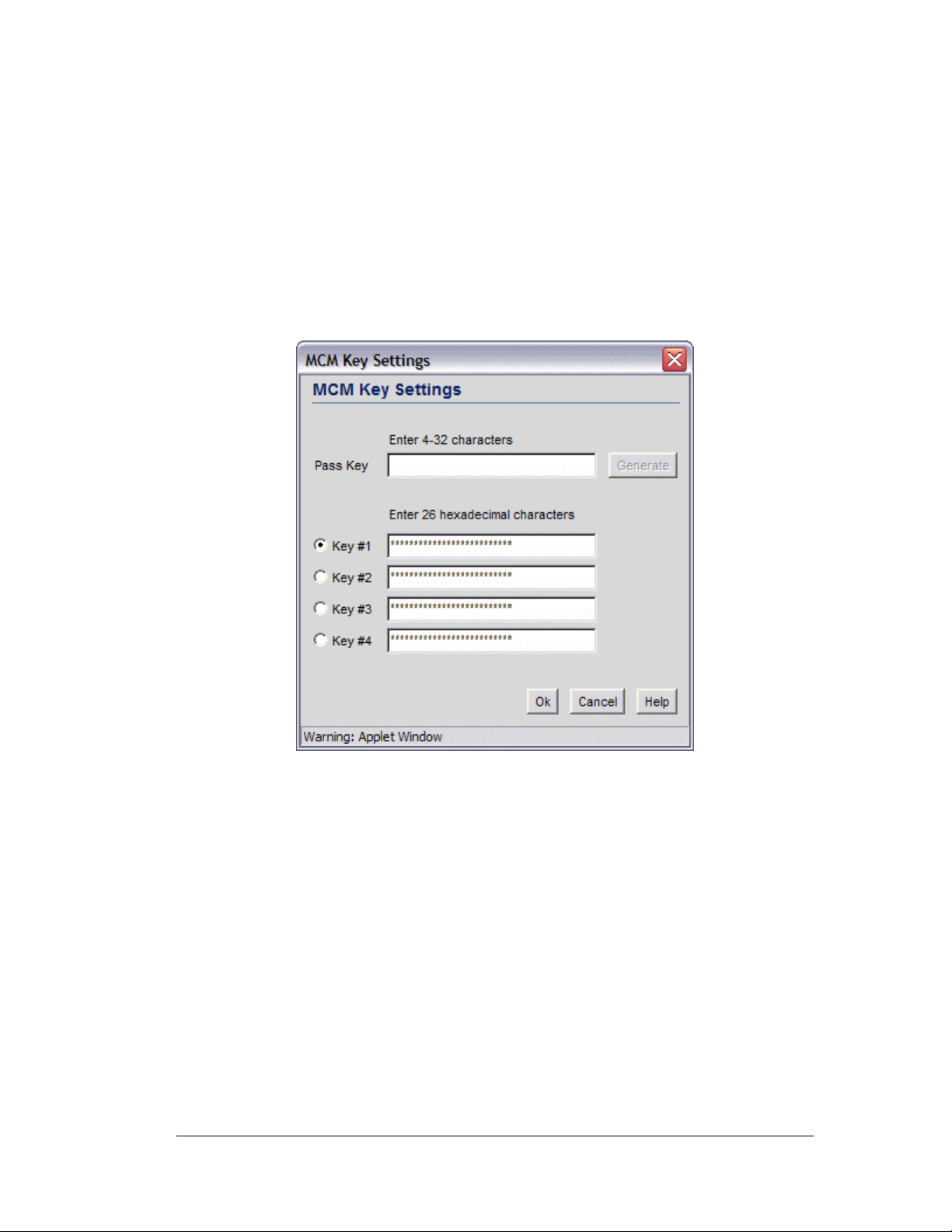
KeyGuard-MCM
KeyGuard-MCM is a proprietary encryption method developed by Symbol Technologies.
KeyGuard is Symbol’s enhancement to WEP encryption and can work with any WEP
device. This encryption method rotates WEP keys for devices that support the method. This
encryption implementation is based on the IEEE Wireless Fidelity (Wi-Fi) standard,
802.11i.
1. Select the KeyGuard-MCM radio button to enable the KeyGuard-MCM encryption
method.
2. To use KeyGuard-MCM encryption with the No Authentication selection, click the
MCM Key Settings button to display a sub-screen for entering keys. (Note that these
are the same keys specified for WEP encryption.
Step 6: Configure WLAN Security
3. Select a Key # radio button to enter to enter or change a passkey.
4. Specify a pass key string in the Pass Key field. The pass key can be any alphanumeric
string. The switch, other proprietary routers, and Symbol cards in mobile units (MUs)
use an algorithm to convert an ASCII string to the same hexadecimal number, but this
conversion is not required for a wireless connection.
5. Click the Generate button and the pass key will be entered in the appropriate Key #
field.
6. When finished entering pass keys, click the OK button to close this screen.
7. Click the Apply button on the WLAN Security screen to save changes.
No Encryption
If No Authentication is selected, the No Encryption radio button can disable
encryption on this WLAN. If security is not an issue, this setting avoids the overhead that
an encryption protocol demands on the switch’s processor.
Copyright © 2004 Symbol Technologies, Inc. All Rights Reserved 36
WS 2000 Wireless Switch: 1.0 Date of last Revision: March 2004
Page 37

Mobile Unit Access Control List (ACL)
Use this list to specify which mobile units can or cannot gain access to the WLAN. The list
employs an adoption rule for allowing or denying specific mobile units by way of
exception.
1. Select Allow or Deny from the pull-down list. This rule applies to all mobile units
except those listed in the table. If Allow is visible, the access criteria (MAC addresses)
will be used to indicated which mobile units will be allowed access to the Access Port.
If Deny is visible, the access criteria will be used to indicated which mobile units
should not be allowed access.
2. Click the Add button to add a new entry to the list.
3. Each entry in the table specifies one or more MAC address to be used to match with a
mobile unit’s MAC address that is attempting to gain access to the WLAN. Specify a
single address (by specifying Start Address only) or a range of MAC access (by
using both the Start Address and the End Address).
For example, if Allow is selected, all mobile units that match any of the specified MAC
addresses or MAC address ranges in the table can be adopted by the WLAN. If Deny is
selected, all mobile units that match any of the specified MAC addresses or MAC
address ranges in the table cannot be adopted by the WLAN.
4. Click the Apply button to save changes.
Step 7: Configure Access Ports
Step 7: Configure Access Ports
The WS 2000 Wireless Switch automatically detects Access Ports when they are attached to
one of the switch’s LAN ports. When the switch starts communication with an Access Port
that can be adopted by the switch, it uploads the firmware appropriate for the Access Port.
At this time, the Access Port becomes active. The switch also automatically adds the Access
Port to the list of known ports under the left menu item, Network Configuration -->
Wireless --> Access Ports--> <Access Port Name>.
For an Access Port to be adopted by the WS 2000 Wireless Switch, three things must be
configured:
1. The Country field in the System Settings screen must be set.
2. The Access Port’s MAC address must be set as one of the addresses that can be adopted
by one of the enabled WLANs. (see Step 4)
3. A WLAN that can adopt Access Port must be associated with an enabled subnet. (see
Step 5)
The switch can adopt up to six Access Ports at a time, but the number of Access Ports listed
can exceed six in number. A dual-radio 802.11a/b Access Port counts as one Access Port
with respect to the maximum allowed; however, each radio will be listed as a separate
Access Port in the list of Access Ports.
The switch creates a default name for a newly found switch consisting of “AP” and a
unique number. During this detection process, the switch collects the following information
from the Access Port:
• MAC address—Each access port has a unique Media Access Control (MAC) address
by which it is identified. This address is burned into the ROM of the access port. Also,
this address appears on a sticker attached to the bottom of the Access Port.
Copyright © 2004 Symbol Technologies, Inc. All Rights Reserved 37
WS 2000 Wireless Switch: 1.0 Date of last Revision: March 2004
Page 38

Step 7: Configure Access Ports
• Radio type—This field indicates the wireless protocol that the Access Port follows.
The WS 2000 Wireless Switch supports 802.11b and 802.11 a/b dual-radio Access
Ports.
• Physical port—This field specifies the physical LAN port on the switch to which the
Access Port is connected.
• Adopted by—This field contains a list of defined WLANs that have adopted this
Access Port (see Enable Wireless LANs and Access Port Adoption for the process of
adopting an Access Port)
The switch also sets several default values for the channel and the power level based upon
the Location information set in the System Settings screen and upon settings in the Default
Access Port Settings screen for the radio type.
The WS 2000 Wireless Switch GUI also allows the administrator to refine the basic Access
Port configuration that is set at the point of detection. To examine or change that
information:
4. Select Network Configuration --> Wireless --> Access Ports from the left menu
and then click the + to the left of the menu item. The detected Access Ports will be
listed under the menu item.
5. Select the Access Port item to examine or modify. There are two ways to distinguish
between Access Ports when they are labeled with the default “AP#” name.
• Look on the bottom of the Access Ports and take note of the MAC address (which
looks like AA:BB:CC:DD EE:FF) and compare it with the MAC address in the
Access Port windows.
• Note the order in which Access Ports were plugged into the switch. The Access
Port numbers are assigned in order, starting with AP1.
The following screen is displayed with the settings for the selected Access Port:
Copyright © 2004 Symbol Technologies, Inc. All Rights Reserved 38
WS 2000 Wireless Switch: 1.0 Date of last Revision: March 2004
Page 39

Step 8: Configure Subnet Access
6. From this screen, the administrator can change several pieces of information about each
Access Port.
Field Description
Name
Location
Placement
Channel
Power Level
Administrators can change the names of the Access Ports
from
Access Port# to something much more descriptive so
that they can easily identify which Access Port is being
referenced in the various screens and in the left menu. The
name is limited to a string of 13 characters.
This field is a memory aid for the administrator. Enter text
that describes where the Access Port is physically located.
The name is limited to a string of 13 characters.
Select either Indoors or Outdoors from the Placement
pop-up menu. The setting will affect the selection available
for several of the other advanced settings.
Specify a channel for communications between the Access
Port and mobile units. The range of legally approved
communications channels varies depending on the
installation location. It is best to use a different channel
number for each Access Port. Communications will be the
clearest for nearby Access Ports if the channel numbers are
5 numbers apart (1, 6, 11).
Specify a Power Level in milliwatts (mW) for RF signal
strength. The optimal power level is best determined by a site
survey prior to installation. Available settings include 1, 5, 15,
30 and 100. Consult the site survey for recommendations for
the power level.
Set a higher power level to ensure RF coverage in WLAN
environments that have more electromagnetic interference or
greater distances between the Access Port and mobile units.
Decrease the power level according to the proximity of other
Access Ports. Overlapping RF coverage may cause lost
packets and difficulty for roaming mobile units trying to
engage an Access Port.
7. Click Apply to save changes.
This screen also provides the ability to change several advanced settings for the Access
Ports. For more information, see Advanced Access Port Settings.
Step 8: Configure Subnet Access
The WS 2000 Network Management System allows the administrator to set up access rules
for subnet-to-subnet and subnet-to-WAN communication. These access rules control
communication between subnets and the outside world (the WAN). Select Network
Configuration --> Subnet Access to get to the Subnet Access screen.
Copyright © 2004 Symbol Technologies, Inc. All Rights Reserved 39
WS 2000 Wireless Switch: 1.0 Date of last Revision: March 2004
Page 40

Step 8: Configure Subnet Access
The Access Overview Table
In the overview table, each of the rectangles represents a subnet association. The three
possible colors indicate the current access level, as defined, for each subnet association.
Color Access Type Description
Green
Yellow
Red
Full Access No protocol exceptions (rules) are specified. All
Limited Access One or more protocol rules are specified. Specific
No Access All protocols are denied, without exception. No traffic
The Access Exception Area
In the lower half of the screen, the access is controlled by specify rules that control the
protocols that are allowed or denied between the two subnets or the subnet and the WAN.
All rules are added to the exception table. The Allow or Deny menu item applies to all
entries in the table. There are two ways to add entries (access rules) to the table. The first is
by checking the checkboxes for specific protocols (on the left). The second is by adding
rules for specific port numbers by clicking the Add button and filling in the necessary
information. A combination of the two methods can be used to add multiple entries to the
table.
traffic may pass between these two areas.
protocols are either enabled or disabled between
these two areas. Click the table cell of interest and
look at the exceptions area in the lower half of the
screen to determine the protocols that are either
allowed or denied.
will pass between these two areas.
You can allow or deny communication through specific protocols using the following
process.
Copyright © 2004 Symbol Technologies, Inc. All Rights Reserved 40
WS 2000 Wireless Switch: 1.0 Date of last Revision: March 2004
Page 41

Step 8: Configure Subnet Access
1. Click in a cell of the table that represents the subnet-to-subnet (or subnet-to-WAN)
relationship to define. All access rules (if any are defined) appear in the table in the
lower-half of the screen.
2. Use the pulldown menu above the list Allow or Deny all the entries specified in the
exception table. You cannot allow some protocols (or ports) and deny others.
3. From the list of checkboxes on the left side, select those protocols to allow or deny. The
protocols are automatically added to the table with the relevant Name, Transport, Start
Port, and End Port information. The available protocols are:
Protocol Transport,
Port Used
HTTP
TELNET
FTP
SMTP
POP
TCP, 80 Hypertext Transfer Protocol (HTTP) is the protocol for
TCP, 23 TELNET is the terminal emulation protocol of TCP/IP.
TCP, 21 File Transfer Protocol (FTP) is an application protocol
TCP, 25 Simple Mail Transfer Protocol (SMTP) is a TCP/IP
TCP, 109:110 Post Office Protocol (POP3) is a TCP/IP protocol
Description
transferring files on the World Wide Web. HTTP is an
application protocol that runs on top of the TCP/IP suite
of protocols, the foundation protocols for the Internet.
TELNET uses TCP to achieve a virtual connection
between server and client, then negotiates options on
both sides of the connection.
that uses the Internet’s TCP/IP protocols. FTP provides
a simple and efficient way to exchange files between
computers on the Internet.
protocol used for sending and receiving email. Due to
its limited ability to queue messages at the receiving
end, SMTP is often used with POP3 or IMAP. SMTP
sends the email, and then POP3 or IMAP receives the
email.
intended to permit a workstation to dynamically access
a maildrop on a server host. A workstation uses POP3
to retrieve email that the server is holding for it.
DNS
TCP+UDP, 53 Domain Name Service (DNS) protocol searches for
resources using a database that is distributed among
different name servers.
• You can make changes to the information automatically filled into the table;
however, note that changes in the selected transport type can change the port
numbers that can be specified in the table.
4. To add an access rule for a protocol, port, or transport other than the ones available
from the checkboxes on the left, click the Add button. An empty row is added to the
table.
• Specify a Name to identify the new access rule. This could be the name of a
particular application, for example.
Copyright © 2004 Symbol Technologies, Inc. All Rights Reserved 41
WS 2000 Wireless Switch: 1.0 Date of last Revision: March 2004
Page 42

Step 8: Configure Subnet Access
• Select a transport type from the Transport column’s pulldown menu. The
available transports are:
Transport Description
ALL
TCP
UDP
ICMP
AH
This selection designates all of the protocols displayed in the
table’s pull-down list, as described below.
Transmission Control Protocol (TCP) is a set of rules used with
Internet Protocol (IP) to send data as message units over the
Internet. While IP handles the actual delivery of data, TCP
keeps track of individual units of data called packets. Messages
are divided into packets for efficient routing through the Internet.
User Datagram Protocol (UDP) is mostly used for broadcasting
data over the Internet. Like TCP, UDP runs on top of Internet
Protocol (IP) networks. Unlike TCP/IP, UDP/IP provides very
few error recovery services and methods. UDP offers a way to
directly connect, and then send and receive datagrams over an
IP network.
Internet Control Message Protocol (ICMP) is tightly integrated
with IP. ICMP messages, delivered in IP packets, are used for
out-of-band messages related to network operation. Because
ICMP uses IP, ICMP packet delivery is unreliable. Hosts cannot
count on receiving ICMP packets for a network problem.
Authentication Header (AH) is one of the two key components of
IPsec (IP Security Protocol). The other key component is
Encapsulating Security Protocol (ESP), described below.
AH provides authentication, proving the packet sender really is
the sender, and the data really is the data sent. AH can be used
in transport mode, providing security between two end points.
Also, AH can be used in tunnel mode, providing security like that
of a Virtual Private Network (VPN).
ESP
GRE
Encapsulating Security Protocol (ESP) is one of the two key
components of IPsec (IP Security Protocol). The other key
component is Authentication Header (AH), described above.
ESP encrypts the payload of packets, and also provides
authentication services. ESP can be used in transport mode,
providing security between two end points. Also, ESP can be
used in tunnel mode, providing security like that of a Virtual
Private Network (VPN).
General Routing Encapsulation (GRE) supports VPNs across
the Internet. GRE is a mechanism for encapsulating network
layer protocols over any other network layer protocol. Such
encapsulation allows routing of IP packets between private IP
networks across an Internet that uses globally assigned IP
addresses.
• Specify port information for the protocol. If a protocol uses only one port, enter the
same port number in the Start Port and End Port columns, or leave the End
Port column blank. Otherwise, use both columns for an entry that has a range of
ports.
5. Click the Apply button to save changes.
Copyright © 2004 Symbol Technologies, Inc. All Rights Reserved 42
WS 2000 Wireless Switch: 1.0 Date of last Revision: March 2004
Page 43

WLAN—How to Configure Advanced Settings
Chapter 4. Advanced Configuration
WLAN—How to Configure Advanced Settings
The lower section of the WLAN screen provides several settings that the administrator
might need to modify; however, the default settings are usually sufficient for most
installations.
1. Check the Disallow MU to MU Communications checkbox to enable a
communication block between mobile units (MUs) using this WLAN. Such
communication might be a security issue, for example, on a corporate network. Leave
this checkbox unchecked (default setting) to allow MU-to-MU communications on this
WLAN.
2. Check the Use Voice Prioritization checkbox to enable WLAN prioritization of
voice over data transmissions. This reduces the latency that might occur when data
transmissions and Voice over IP (VoIP) transmissions compete for the same resources.
Latency is experienced as broken or delayed speech or sound. Disable this option if
VoIP equipment is not in use on this WLAN. The default setting is unchecked.
3. Check the Answer Broadcast ESS checkbox to enable adopted Access Ports to transmit
the WLAN’s Extended Service Set Identification (ESSID). The purpose of allowing
WLANs to answer the broadcast ESS is to identify Access Ports that are associated with
the WLAN. This might be appropriate, for example, in a customer environment, such as
a “hot spot.”
4. Disable this option if broadcasting the WLAN’s ESSID poses a security risk, such as on
a private, corporate network. The default setting is unchecked.
Copyright © 2004 Symbol Technologies, Inc. All Rights Reserved 43
WS 2000 Wireless Switch: 1.0 Date of last Revision: March 2004
Page 44
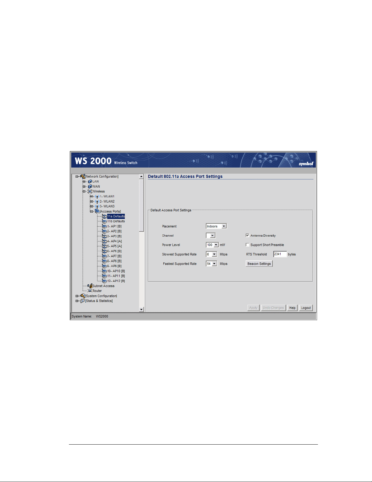
WLAN—Setting Default Access Port Settings
5. Use the Multicast Address 1 and Multicast Address 2 to specify one or two MAC
addresses to be used for multicast applications. Some VoIP devices make use of
multicast addresses. This mechanism ensures that the multicast packets for these
devices are not delayed by the packet queue.
6. Click the Apply button to save changes.
WLAN—Setting Default Access Port Settings
The WS 2000 Network Switch can support up to six Access Port. These Access Ports can
be either a 802.11a or 802.11b radio type. When an Access Port associates with the wireless
switch, the initial settings for that Access Port are taken from the Default Access Port
Setting for the appropriate radio type.. Select Network Configuration --> Wireless -->
Access Ports --> Default 802.11 a/b Settings from the left menu to view and set the
default properties for all the two radio types.
Fill out the default information as indicated below:
1. Select either Indoors or Outdoors from the Placement pop-up menu. This setting
will affect the power levels and channels available for selection.
2. Select a channel number from the Channel drop-down list on which the Access Port
should communicate with associated MUs.
Note: The available channels vary depending on the location setting of
the switch.
3. Select a power level from the Power Level drop-down list that will be used for radio
communications between the Access Port and the MUs.
4. Select both the Slowest Supported Rate and the Fastest Supported Rate from
the respective drop-down lists to specify the allowable transmission rates for
communication between the Access Port and the associated MUs.
Copyright © 2004 Symbol Technologies, Inc. All Rights Reserved 44
WS 2000 Wireless Switch: 1.0 Date of last Revision: March 2004
Page 45

WLAN—Setting Default Access Port Settings
5. Check the Antenna Diversity checkbox to enable Antenna Diversity if the Access
Port has an external antenna. Antenna Diversity should only be enabled if the Access
Port has two matching external antennas.
6. Check the Support Short Preamble checkbox to allow the Access Port to
communicate with the MUs using a short 56-bit preamble.
A preamble is the beginning part of a frame. The preamble comprises such elements as
robust carrier sensing, collision detection, equalizer training, timing recovery, and gain
adjustment. The administration can choose between a long or short preamble for dataframe transmission from the WLAN’s adopted access ports.
Use the long preamble setting (the default) for legacy wireless equipment that is not
capable of dealing with short preambles. Use the short preamble setting where legacy
equipment is not an issue and maximum throughput is desired, for example when
streaming video or Voice-over-IP applications are used.
7. Set the Request to Send Threshold (RTS Threshold) by specifying a number.
RTS is a transmitting station’s signal that requests a Clear To Send (CTS) response
from a receiving station. This RTS/CTS procedure clears the air when many mobile
units (MUs) are contending for transmission time. Modifying this value allows the
administrator to control the number of data collisions and thereby enhance
communication with nodes that are hard to find because of other active nodes in the
transmission path.
In this field, the administrator can specify a Request To Send (RTS) threshold (in bytes)
for use by the WLAN’s adopted access ports.
This setting initiates an RTS/CTS exchange for data frames that are larger than the
threshold, and sends (without RTS/CTS) any data frames that are smaller than the
threshold.
Consider the tradeoffs when setting an appropriate RTS threshold for the WLAN’s
access ports. A lower RTS threshold causes more frequent RTS/CTS exchanges. This
consumes more bandwidth because of the additional latency (RTS/CTS exchanges)
before transmissions can commence. A disadvantage is the reduction in data-frame
throughput. An advantage is quicker system recovery from electromagnetic interference
and data collisions. Environments with more wireless traffic and contention for
transmission make the best use of a lower RTS threshold.
A higher RTS threshold minimizes RTS/CTS exchanges, consuming less bandwidth for
data transmissions. A disadvantage is less help to nodes that encounter interference and
collisions. An advantage is faster data-frame throughput. Environments with less
wireless traffic and contention for transmission make the best use of a higher RTS
threshold.
Set the Access Port beacon settings by clicking on the Beacon Settings button. The
following window appears.
Copyright © 2004 Symbol Technologies, Inc. All Rights Reserved 45
WS 2000 Wireless Switch: 1.0 Date of last Revision: March 2004
Page 46
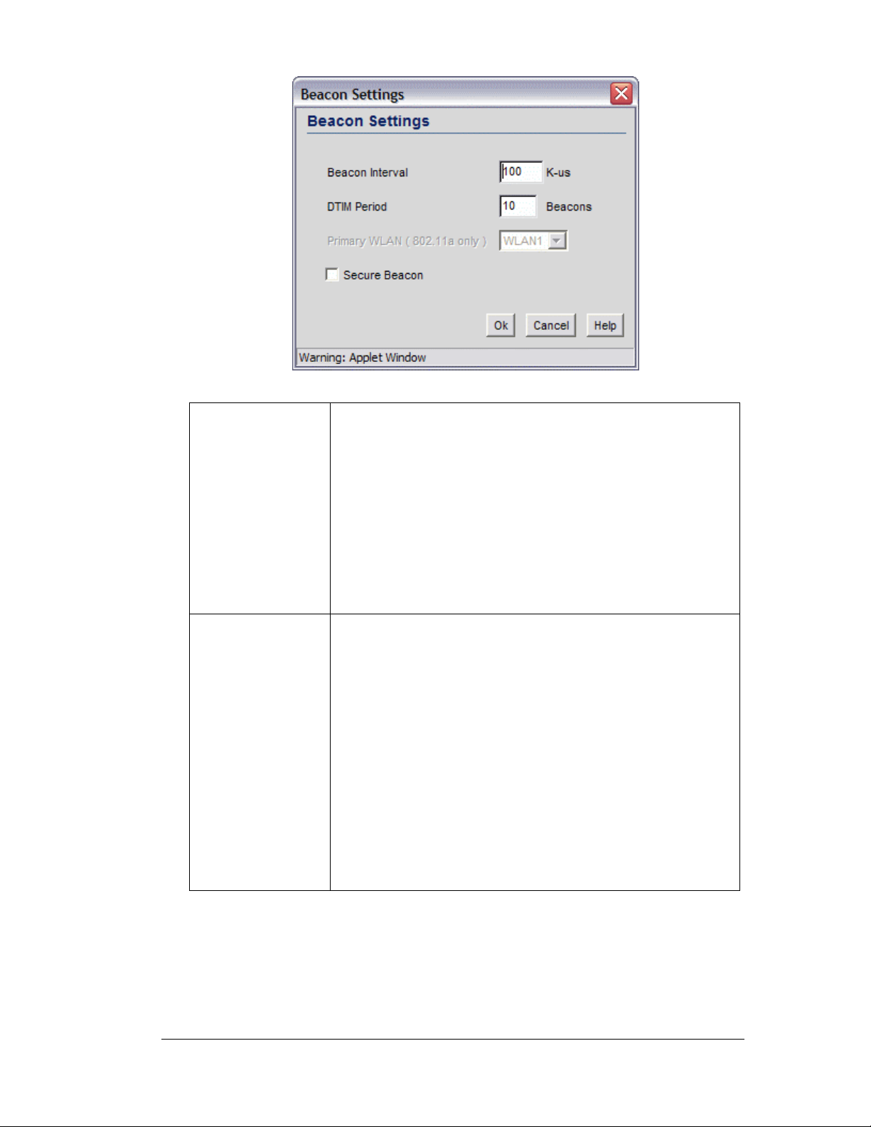
WLAN—Setting Default Access Port Settings
8. Set the beacon values as indicated in the table below.
Beacon Interval
DTIM Period
A beacon is a packet broadcast by the adopted access ports
to keep the network synchronized. Included in a beacon is
information such as the WLAN service area, the access-port
address, the broadcast destination addresses, a time stamp,
and indicators about traffic and delivery such as a DTIM.
Specify a beacon interval in units of 1,000 microseconds
(K-us). This is a multiple of the DTIM value, for example,
100 : 10. Increase the DTIM/beacon settings, lengthening
the time, to let nodes sleep longer and preserve their battery
life. Decreasing this value (shorten the time) to support
streaming-multicast audio and video applications that are
jitter-sensitive.
A DTIM is periodically included in the beacon frame that is
transmitted from adopted access ports. The DTIM period
determines how often the beacon contains a DTIM, for
example, 1 DTIM for every 10 beacons. The DTIM indicates
that broadcast and multicast frames, buffered at the access
port, are soon to arrive. These are simple data frames that
require no acknowledgment, so nodes sometimes miss
them.
In this field, the administrator can specify a period for the
Delivery Traffic Indication Message (DTIM). This is a divisor
of the beacon interval (in milliseconds); for example, 10 :
100. Increase the DTIM/beacon settings, lengthening the
time, to let nodes sleep longer and preserve their battery life.
Decrease this settings (shortening the time) to support
streaming-multicast audio and video applications that are
jitter-sensitive.
Copyright © 2004 Symbol Technologies, Inc. All Rights Reserved 46
WS 2000 Wireless Switch: 1.0 Date of last Revision: March 2004
Page 47
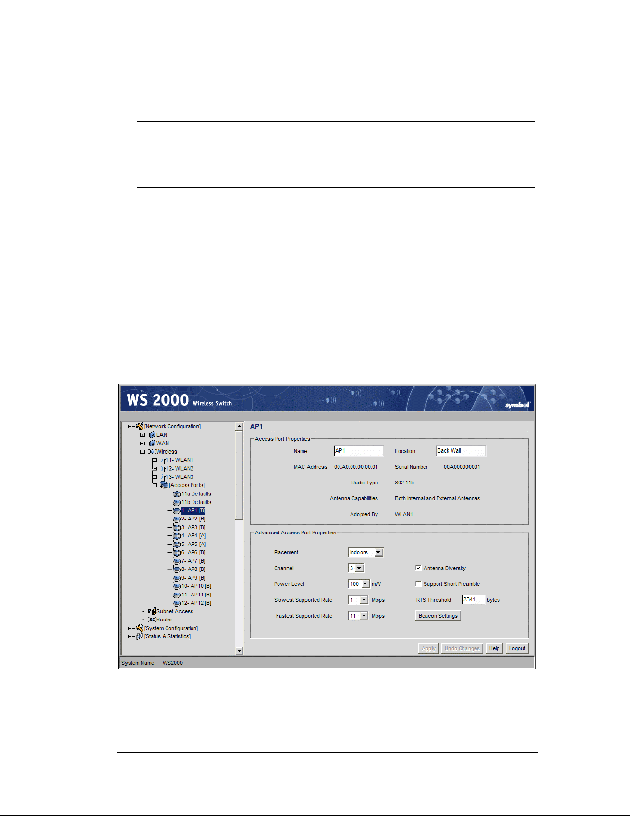
WLAN—Advanced Access Port Settings
Primary WLAN
Security Beacon
Set the Primary WLAN field when the 802.11a broadcast
protocol is used. When a WLAN is associated with a
801.11a broadcaster only one ESSID can be broadcast from
the Access Port (even though three are supported by the
switch) . This field specifies which ESSID to broadcast.
Select the Security Beacon checkbox if the WLAN
associated with the Access Port needs to be secure. If this
feature is selected, the WLAN will not broadcast the ESSID.
This selection eliminates the possibility of hackers tapping in
to the WLAN without authorization by “stealing” the ESSID.
9. Click OK when finished setting the beacon settings.
10. Click the Apply button to save changes
WLAN—Advanced Access Port Settings
The WS 2000 Wireless Switch GUI allows the administrator to configure the Access Port
settings. To examine or change that information:
1. Select Network Configuration --> Wireless --> Access Ports from the left menu
and then click the + to the left of the menu item. The detected Access Ports will be
listed under the menu item.
2. Select the Access Port to examine or modify.
When the Access Port Name menu item is selected, the following screen will appear:
Copyright © 2004 Symbol Technologies, Inc. All Rights Reserved 47
WS 2000 Wireless Switch: 1.0 Date of last Revision: March 2004
Page 48

WLAN—Advanced Access Port Settings
The advanced Access Port settings are found at the bottom of the screen. For most
installations, the default settings for the advanced settings are appropriate.
1. Select either Indoors or Outdoors from the Placement pop-up menu. The setting will
affect the selection available for several of the other advanced settings.
2. Select a channel number from the Channel drop-down list on which the Access Port
should communicate with associated MUs. (The available channels vary depending on
the location setting of the switch.)
3. Select a power level from the Power Level drop-down list that will be used for radio
communications between the Access Port and the MUs.
4. Select both the Slowest Supported Rate and the Fastest Supported Rate from
the respective drop-down lists to specify the allowable transmission rates for
communication between the Access Port and the associated MUs.
5. Check the Antenna Diversity checkbox to enable Antenna Diversity if the Access
Port has an external antenna.
6. Check the Support Short Preamble checkbox to allow the Access Port to
communicate with the MUs using a short 56-bit preamble.
A preamble is the beginning part of a frame. The preamble comprises such elements as
robust carrier sensing, collision detection, equalizer training, timing recovery, and gain
adjustment. The administration can choose between a long or short preamble for dataframe transmission from the WLAN’s adopted access ports.
Use the long preamble setting (the default) for legacy wireless equipment that is not
capable of dealing with short preambles. Use the short preamble setting where legacy
equipment is not an issue and maximum throughput is desired, for example when
streaming video or Voice-over-IP applications are used.
7. Set the Request to Send Threshold (RTS Threshold) by specifying a number.
RTS is a transmitting station’s signal that requests a Clear To Send (CTS) response
from a receiving station. This RTS/CTS procedure clears the air when many mobile
units (MUs) are contending for transmission time. Modifying this value allows the
administrator to control the number of data collisions and thereby enhance
communication with nodes that are hard to find because of other active nodes in the
transmission path.
In this field, the administrator can specify a Request To Send (RTS) threshold (in bytes)
for use by the WLAN’s adopted access ports.
This setting initiates an RTS/CTS exchange for data frames that are larger than the
threshold, and sends (without RTS/CTS) any data frames that are smaller than the
threshold.
Consider the tradeoffs when setting an appropriate RTS threshold for the WLAN’s
access ports. A lower RTS threshold causes more frequent RTS/CTS exchanges. This
consumes more bandwidth because of the additional latency (RTS/CTS exchanges)
before transmissions can commence. A disadvantage is the reduction in data-frame
throughput. An advantage is quicker system recovery from electromagnetic interference
and data collisions. Environments with more wireless traffic and contention for
transmission make the best use of a lower RTS threshold.
A higher RTS threshold minimizes RTS/CTS exchanges, consuming less bandwidth for
data transmissions. A disadvantage is less help to nodes that encounter interference and
collisions. An advantage is faster data-frame throughput. Environments with less
wireless traffic and contention for transmission make the best use of a higher RTS
threshold.
Copyright © 2004 Symbol Technologies, Inc. All Rights Reserved 48
WS 2000 Wireless Switch: 1.0 Date of last Revision: March 2004
Page 49
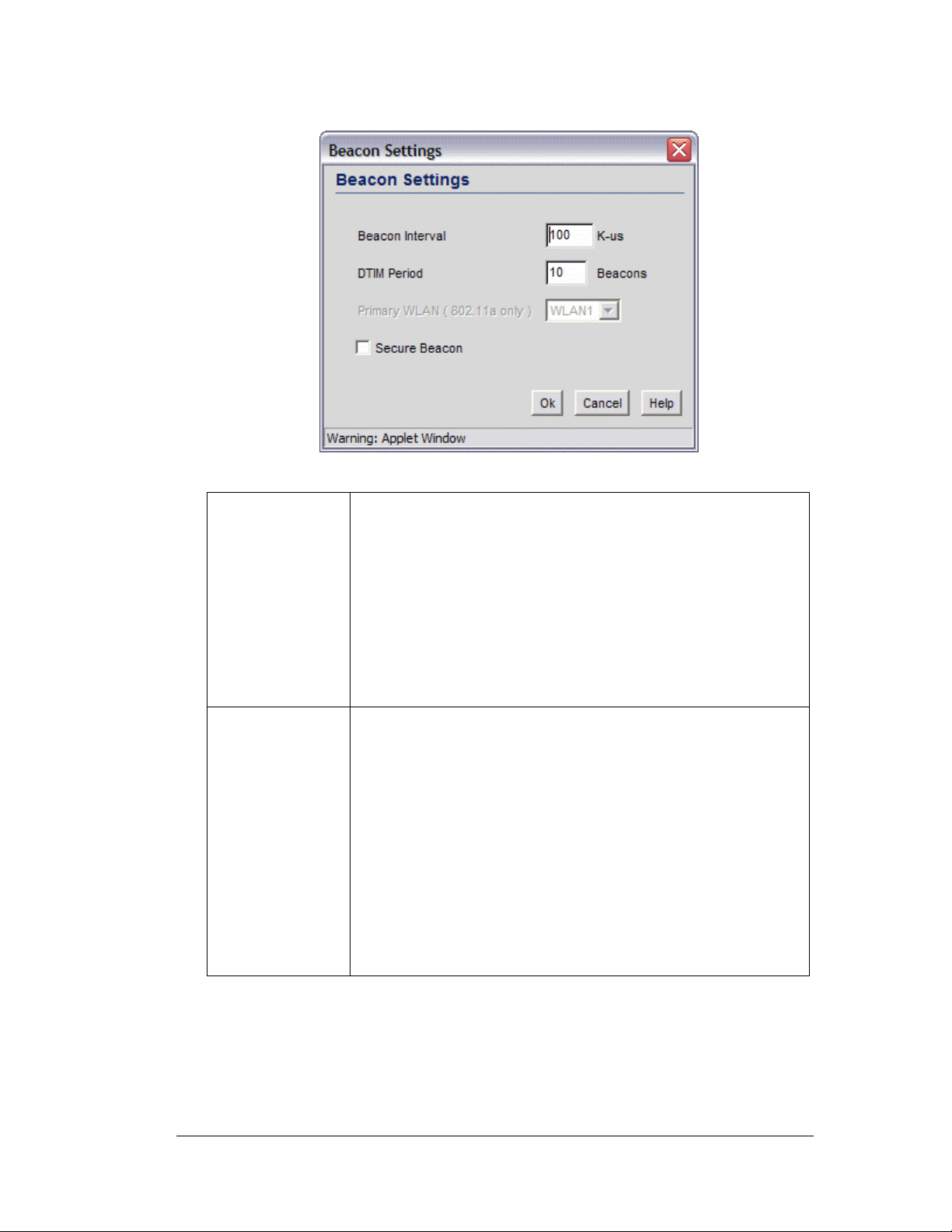
WLAN—Advanced Access Port Settings
8. Set the Access Port beacon settings by clicking on the Beacon Settings button. The
following window appears.
9. Set the beacon values as indicated in the table below.
Beacon Interval
DTIM Period
A beacon is a packet broadcast by the adopted access ports to
keep the network synchronized. Included in a beacon is
information such as the WLAN service area, the access-port
address, the broadcast destination addresses, a time stamp,
and indicators about traffic and delivery such as a DTIM.
Specify a beacon interval in units of 1,000 microseconds (K-us).
This is a multiple of the DTIM value, for example, 100 : 10.
Increase the DTIM/beacon settings, lengthening the time, to let
nodes sleep longer and preserve their battery life. Decreasing
this value (shorten the time) to support streaming-multicast
audio and video applications that are jitter-sensitive.
A DTIM is periodically included in the beacon frame that is
transmitted from adopted access ports. The DTIM period
determines how often the beacon contains a DTIM, for example,
1 DTIM for every 10 beacons. The DTIM indicates that
broadcast and multicast frames, buffered at the access port, are
soon to arrive. These are simple data frames that require no
acknowledgment, so nodes sometimes miss them.
In this field, the administrator can specify a period for the
Delivery Traffic Indication Message (DTIM). This is a divisor of
the beacon interval (in milliseconds); for example, 10 : 100.
Increase the DTIM/beacon settings, lengthening the time, to let
nodes sleep longer and preserve their battery life. Decrease this
settings (shortening the time) to support streaming-multicast
audio and video applications that are jitter-sensitive.
Copyright © 2004 Symbol Technologies, Inc. All Rights Reserved 49
WS 2000 Wireless Switch: 1.0 Date of last Revision: March 2004
Page 50
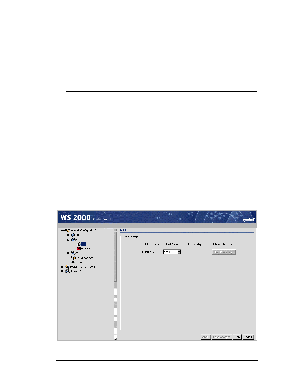
Gateway—How to Configure Network Address Translation (NAT)
Primary WLAN
Security Beacon
Set the Primary WLAN field when the 802.11a broadcast
protocol is used. When a WLAN is associated with a 801.11a
broadcaster only one ESSID can be broadcast from the Access
Port (even though three are supported by the switch) . This field
specifies which ESSID to broadcast.
Select the Security Beacon checkbox if the WLAN associated
with the Access Port needs to be secure. If this feature is
selected, the WLAN will not broadcast the ESSID. This selection
eliminates the possibility of hackers tapping in to the WLAN
without authorization by “stealing” the ESSID.
10. Click OK when finished setting the beacon settings.
11. Click Apply in the Access Port window to save changes.
Gateway—How to Configure Network Address Translation
(NAT)
NAT provides the translation of an Internet Protocol (IP) address within one network to a
different, known IP address within another network. One network is designated the private
network, while the other is the public. NAT provides a layer of security by translating
private (local) network addresses to one or more public IP addresses. For example, when an
administrator wants to allow individuals on the WAN side access to a particular FTP or web
server that is located on one of the LAN subnets but does not want to permit any other
access, NAT is the appropriate solution.
1. Select Network Configuration --> WAN --> NAT from the left menu. The following
screen appears.
Copyright © 2004 Symbol Technologies, Inc. All Rights Reserved 50
WS 2000 Wireless Switch: 1.0 Date of last Revision: March 2004
Page 51
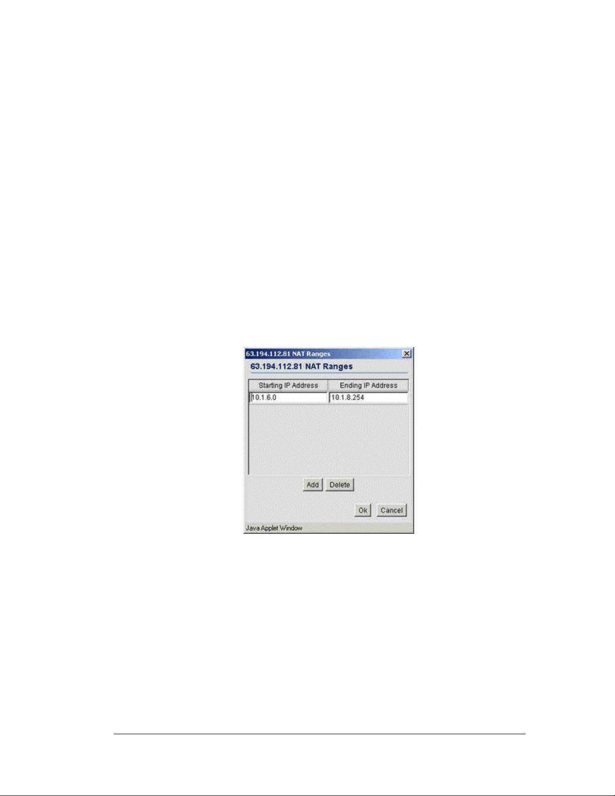
Gateway—How to Configure Network Address Translation (NAT)
This screen displays the IP addresses specified in the WAN screen (Network
Configuration --> WAN from the left menu). Up to eight WAN addresses can be
associated with the switch. The NAT screen enables the administrator to set of the type
of translation and port forwarding required.
2. For each of the addresses, the select the NAT type.
• Select 1 to 1 from the pull-down menu to map a WAN IP address to a single local
(subnet) IP address. This selection is useful in situations in which users require
dedicated IP addresses or when public-facing servers are connected to the switch.
• Select 1 to Many from the pull-down menu to map a WAN IP address to a range
of local IP addresses. Use this option when there are fewer public IP address on the
WAN than there are users on the LAN. 1 to Many NAT allows a single IP address
to handle traffic from multiple private LAN IP addresses.
• Select None from the pull-down menu when the administrator sets up routable IP
addresses (set on the Network Configuration --> Routing screen).
3. If the NAT type is 1 to 1, the Outbound Mappings field allows the administrator to
specify a single IP Address. This address specifies the 1 to 1 mapping between the
WAN IP address the specified LAN IP address.
4. If the NAT type is 1 to Many, the NAT Ranges button in the adjacent Host IP
Address field is active, allowing the administrator to specify a address-range
assignment. To set up the ranges click the NAT Ranges button.
Within the NAT Ranges sub-screen, the administrator can specify several IP
addresses or IP address ranges. Click the Add button to add a new entry. Click the
Delete button to remove an entry.
5. Click the Port Forwarding button to display a sub-screen of port forwarding
parameters for inbound traffic from the associated WAN IP address. When finished,
click the OK button to close the screen.
6. Click the Apply button on the NAT screen to save changes.
Copyright © 2004 Symbol Technologies, Inc. All Rights Reserved 51
WS 2000 Wireless Switch: 1.0 Date of last Revision: March 2004
Page 52
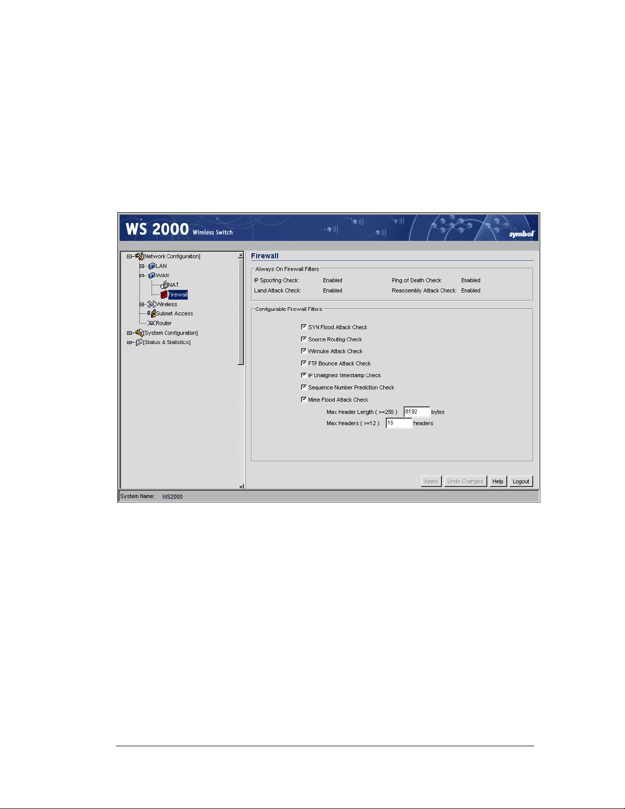
Gateway—How to Configure the WS 2000 Firewall
Gateway—How to Configure the WS 2000 Firewall
The WS 2000 Wireless Switch provides a secure firewall / Network Address Translation
(NAT) solution for the WAN uplink. The firewall includes a proprietary CyberDefense
Engine to protect internal networks from known Internet attacks. It also provides additional
protection by performing source routing, IP unaligned timestamp, and sequence number
prediction. The firewall uses a collection of filters to screen information packets for known
types of system attacks. Some of the switch’s filters are always enabled, and others are
configurable.
To view or change the firewall settings, select Network Configuration --> WAN -->
Firewall from the left menu.
Always On Firewall Filters
The filters that are permanently enabled prevent unauthorized and potentially damaging
access checks for IP spoofing, land attack, ping of death, and reassembly attack.
• IP spoofing is the creation of TCP/IP packets that illegitimately use (or “spoof” ) the
source IP address of a trusted host when sent.
• A land attack is the creation of a packet that uses the same IP address for both the
source-host port and destination-host port when sent.
• The “ping of death” is a type of denial of service attack in which a packet is sent that
exceeds the packet size (in bytes) allowed by the IP protocol.
• A reassembly attack uses a reassembly algorithm for sending packets that result in
overlapping fragments (overwritten data).
Copyright © 2004 Symbol Technologies, Inc. All Rights Reserved 52
WS 2000 Wireless Switch: 1.0 Date of last Revision: March 2004
Page 53

Configurable Firewall Filters
The administrator can enabled or disabled the following filters. By default, all these filters
are activated. If it reasonable to turn off the filters if one of the following things is true:
• The switch is on a completely isolated network with no access to the Internet and is
therefore secure.
• The switch is heavily loaded a slight increase in performance outweighs the safety of
the network.
• Blocking these types of attacks would also block legitimate traffic on their network
(although this scenario is highly unlikely.
SYN Flood Attack Check
A SYN flood attack requests a connection and then fails to promptly acknowledge a
destination host’s response, leaving the destination host vulnerable to a flood of connection
requests.
Source Routing Check
A source routing attack specifies an exact route for a packet’s travel through a network,
while exploiting the use of an intermediate host to gain access to a private host.
Gateway—How to Configure the WS 2000 Firewall
Winnuke Attack Check
A “Win-nuking” attack uses the IP address of a destination host to send junk packets to its
receiving port. This attack is a type of denial of service (DOS) attack that completely
disables networking on systems Microsoft Windows 95 and NT. Because this attack is only
affective on older systems, it may not be necessary to enable this feature on a LAN with
newer Microsoft Windows operating systems or with systems that have the appropriate
“Winnuke” patches loaded.
FTP Bounce Attack Check
An FTP bounce attack uses the PORT command in FTP mode to gain access to arbitrary
ports on machines other than the originating client.
IP Unaligned Timestamp Check
An IP unaligned timestamp attack uses a frame with the IP timestamp option, where the
timestamp is not aligned on a 32-bit boundary.
Sequence Number Prediction Check
A sequence number prediction attack establishes a three-way TCP connection with a forged
source address, and the attacker guesses the sequence number of the destination host’s
response.
Copyright © 2004 Symbol Technologies, Inc. All Rights Reserved 53
WS 2000 Wireless Switch: 1.0 Date of last Revision: March 2004
Page 54

Gateway—How to Configure Static Routes
MIME Flood Attack Check
A MIME flood attack uses an improperly formatted MIME header in “sendmail” to cause a
buffer overflow on the destination host.
• Use the Max Header Length field to set the maximum allowable header length. Set
this value to be at least 256 bytes.
• Use the Max Headers field to set the maximum number of headers allowed. Set this
value to be at least 12.
Click the Apply button to save changes made on this screen.
Gateway—How to Configure Static Routes
A router uses routing tables and protocols to forward data packets from one network to
another. The switch’s router manages traffic within the switch’s network, and directs traffic
from the WAN to destinations on the switch-managed LAN. The WS 2000 Network
Management System provides the Router screen to view and set the router’s connected
routes. To view this screen, select Network Configuration --> Router from the menu on
the left.
The Connected Routes area of the screen displays a list of currently connected routes
between the enabled subnets, the WAN, and the router. The information here is generated
from settings applied on the Subnet and WAN screens. The destination for each subnet is its
IP address. The subnet mask (or network mask) and gateway settings are those belonging to
each subnet, or to the WAN in general. If multiple IP addresses are associated with WAN
communications, all the address will be displayed in the Connected Routes are of the
screen. Also listed here is the default route, which specifies the WAN gateway IP address.
To make changes to the information in the Connected Routes information, go to the
appropriate subnet screen (LAN --> <subnet name> or the WAN screen (WAN).
Copyright © 2004 Symbol Technologies, Inc. All Rights Reserved 54
WS 2000 Wireless Switch: 1.0 Date of last Revision: March 2004
Page 55

Defining Routes
The User Defined and RIP Routes area of the screen allows the administrator to view,
add or delete internal static (dedicated) routes, and to enable or disable routes that are
generated using the Routing Information Protocol (RIP). If RIP is enabled, this table can
also include routes that RIP generates.
This table also includes internal static routes that the administrator adds. Internal static
routes are dedicated routes for data that travels from the WAN, through the switch, and to a
specified subnet. Such routes are supplemental to the default routes already set up for each
of the subnets.
1. Check the Enable RIP checkbox to allow Routing Information Protocol. This is an
internal gateway protocol that specifies how routers exchange routing-table
information. If this option is enabled, RIP-generated entries appear in the associated
table of user-defined and RIP routes.
Disable this option to prohibit the switch’s router from exchanging routing information
with other routers. Routing information may not be appropriate to share, for example, if
the switch manages a private LAN.
2. Click the Add button to create a new table entry.
3. Specify the destination IP address, subnet mask, and gateway information for the
internal static route.
Gateway—How to Configure Static Routes
4. Select an enabled subnet from the Interface column’s drop-down menu to complete
the table entry.
Information in the Metric column is automatically generated, and is used by router
protocols to determine the best hop routes.
5. The Source column automatically displays “User” for a user-added entry. An RIPsourced entry displays “RIP.”
6. Click the Apply button to save changes.
Setting the RIP Configuration
The Routing screen also allows the administrator to select the type of RIP and the type of
RIP authentication used by the switch. To set or view the RIP configuration, click the RIP
Configuration button. The following subscreen appears.
1. Set the RIP type from the RIP Type drop down menu. The options are:
No RIP
RIP v1
Depending on the RIP Direction setting, the No RIP option partially
or completely disallows the switch’s router from exchanging routing
information with other routers. Routing information may not be
appropriate to share, for example, if the switch manages a private
LAN.
RIP version 1 is a mature, stable, and widely supported protocol. It
is well suited for use in stub networks and in small autonomous
systems that do not have enough redundant paths to warrant the
overhead of a more sophisticated protocol.
Copyright © 2004 Symbol Technologies, Inc. All Rights Reserved 55
WS 2000 Wireless Switch: 1.0 Date of last Revision: March 2004
Page 56

Security—How to Configure 802.1x EAP Authentication
RIP v2 (v1
compat)
RIP v2
RIP version 2 (compatible with version 1) is an extension of RIP
v1’s capabilities, but it is still compatible with RIP version 1. RIP
version 2 increases the amount of packet information to provide the
a simple authentication mechanism to secure table updates.
RIP version 2 enables the use of a simple authentication
mechanism to secure table updates. More importantly, RIP version
2 supports subnet masks, a critical feature that is not available in
RIP version 1. This selection is not compatible with RIP version 1
support.
2. Select a routing direction from the RIP Direction drop-down list. Both (for both
directions), Rx only (receive only) and TX only (transmit only) are available options.
3. If RIP v2 or RIP v2 (v1 compat) is the selected RIP type, the RIP v2
Authentication area of the screen becomes active. Select the type of authentication to
use from the Authentication Type drop-down list. Available options are:
None
Simple
MD5
This option disables the RIP authentication.
This option enable RIP version 2’s simple authentication
mechanism.
This setting activates the Password (Simple Authentication) field.
This option enables the MD5 algorithm for data verification. MD5
takes as input a message of arbitrary length and produces a 128-bit
fingerprint. The MD5 algorithm is intended for digital signature
applications, in which a large file must be compressed in a secure
manner before being encrypted with a private (secret) key under a
public-key cryptographic system. The MD5 setting activates the RIP
v2 Authentication settings for keys (below).
4. If the Simple authentication method is selected, specify a password of up to 15
alphanumeric characters in the Password (Simple Authentication) field.
5. If the MD5 authentication method is selected, fill in the Key #1 and Key #2 fields.
Type in any numeric value between 0 and 256 into the MD5 ID field. Type in any string
consisting of 16 alphanumeric characters into the MD5 Auth Key field.
6. Click the OK button to return to the Routing screen.
Security—How to Configure 802.1x EAP Authentication
The IEEE 802.1x is an authentication standard that ties EAP to both wired and wireless
LAN applications. EAP provides effective authentication with or without IEEE 802.1x
Wired Equivalent Privacy (WEP) encryption, or with no encryption at all. EAP supports
multiple authentication measures. It requires that the site have a authentication (Remote
Dial-In User Service—RADIUS) server on the wired side of the Access Port. All other
packet types are blocked until the authentication server verifies the client’s identity. To set
up 802.1x EAP authentication:
1. Go to the Network Configuration --> Wireless --> <WLAN Name> --> <WLAN
Name> Security screen.
2. Select the 802.1x EAP radio button to enable the 802.1x Extensible Authentication
Protocol (EAP).
Copyright © 2004 Symbol Technologies, Inc. All Rights Reserved 56
WS 2000 Wireless Switch: 1.0 Date of last Revision: March 2004
Page 57
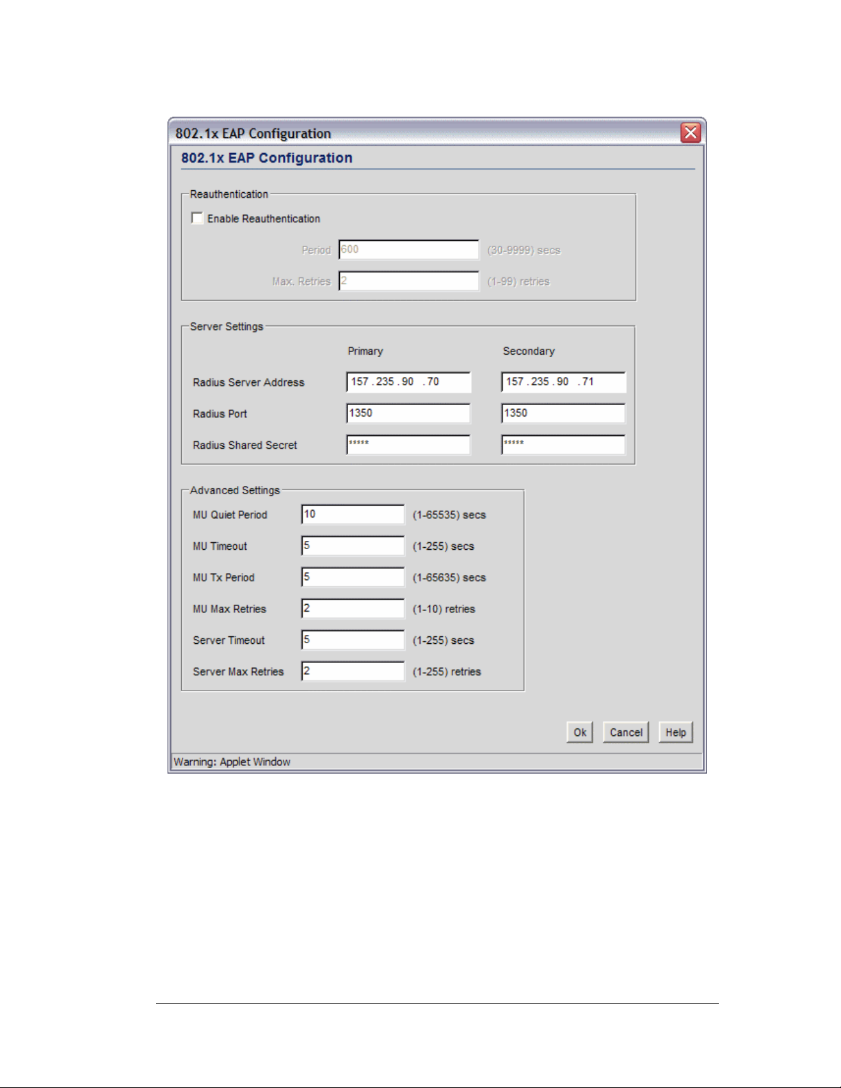
Security—How to Configure 802.1x EAP Authentication
3. Click the 802.1x EAP Configuration button to display a sub-screen for specific
authentication settings.
4. Check the Enable Reauthentication check box to enable this authentication method.
5. Set the EAP reauthentication period to match the appropriate level of security. A shorter
time interval (~ 30 seconds or longer) provides tighter security on this WLAN’s
wireless connections. A longer interval (5000-9999 seconds) relaxes security on
wireless connections. The reauthentication period setting does not affect a wireless
connection’s throughput. The engaged access port continues to forward traffic during
the reauthentication process.
Copyright © 2004 Symbol Technologies, Inc. All Rights Reserved 57
WS 2000 Wireless Switch: 1.0 Date of last Revision: March 2004
Page 58

Security—How to Configure 802.1x EAP Authentication
6. Set the maximum number of retries (Max. Retries) for a client to successfully
reauthenticate after failing to complete the EAP process. If the mobile unit fails the
authentication process in specified number of retries, the switch will terminate the
connection to the mobile unit.
7. The administrator is required to specify the IP address of a primary RADIUS server
for this type of authentication to work. Providing the IP address of a secondary server is
optional. The secondary server acts as a failover server if the switch cannot successfully
contact the primary server.
8. Specify the port on which the primary RADIUS server is listening in the Radius port
field. Optionally, specify the port of a secondary (failover) server. Older RADIUS
servers listen on ports 1645 and 1646. Newer servers listen on ports 1812 and 1813.
Port 1645 or 1812 is used for authentication. Port 1646 or 1813 is used for accounting.
The ISP or a network administrator can confirm the appropriate primary and secondary
port numbers.
9. The administrator can specify a Radius shared secret for authentication on the
primary RADIUS server. Shared secrets are used to verify that RADIUS messages, with
the exception of the Access-Request message, are sent by a RADIUS-enabled device
that is configured with the same shared secret. The shared secret is a case-sensitive
string that can have letters, numbers, or symbols. Make the shared secret at least 22
characters long to protect the RADIUS server from brute-force attacks.
10. The MU Quiet Period field allows the administrator to specify the idle time (in
seconds) between a mobile unit’s authentication attempts, as required by the server.
11. The MU Timeout allows the administrator to specify the time (in seconds) for the
mobile unit’s retransmission of EAP-Request packets.
12. The MU Tx Period field allows the administrator to specify the time period (in
seconds) for the server’s retransmission of the EAP-Request/Identity frame.
13. The MU Max Retries field allows the administrator to set the maximum number of
times for the mobile unit to retransmit an EAP-Request frame to the server before it
times out the authentication session. Note that this is a different value from the Max
Retry field at the top of the window.
14. The Server Timeout indicates the maximum time (in seconds) that the switch will
wait for the server’s transmission of EAP Transmit packets.
15. The Server Max Retries field allows the administrator to set the maximum number
of times for the server to retransmit an EAP-Request frame to the client before it times
out the authentication session. Note that this is a different value from the Max Retry
field at the top of the window.
16. Click the Apply button to save changes.
Copyright © 2004 Symbol Technologies, Inc. All Rights Reserved 58
WS 2000 Wireless Switch: 1.0 Date of last Revision: March 2004
Page 59

Security—How to Configure Kerberos Authentication
Security—How to Configure Kerberos Authentication
Kerberos provides strong authentication method for client/server applications by using
secret-key cryptography. Using this protocol, a client can prove its identity to a server (and
vice versa) across an insecure network connection. After a client and server use Kerberos to
prove their identity, they can encrypt all communications to assure privacy and data
integrity.
1. Select the Kerberos radio button to enable Kerberos authentication.
2. Click the Kerberos Configuration button to display a sub-screen for authentication
settings.
3. A realm name functions similarly to a DNS domain name. In theory, the realm name is
arbitrary; however, in practice a Kerberos realm is typically named using an uppercase
version of the DNS domain name that is associated with hosts in the realm. Specify a
realm name that is case-sensitive, for example, MYCOMPANY.COM.
4. Specify a Username for the Kerberos configuration.
5. Specify a Password for the Kerberos configuration.
The KDC (Key Distribution Center) implements an Authentication Service and a ticket
granting service, whereby an authorized user is granted a ticket that is encrypted with
the user’s password. The KDC has a copy of every user password.
6. Specify a server IP address and a port to be used as the Primary KDC.
7. Optionally, specify a Backup KDC server by providing the IP address and port.
8. Optionally, specify a Remote KDC server by providing the IP address and port.
9. Click OK when done.
Copyright © 2004 Symbol Technologies, Inc. All Rights Reserved 59
WS 2000 Wireless Switch: 1.0 Date of last Revision: March 2004
Page 60
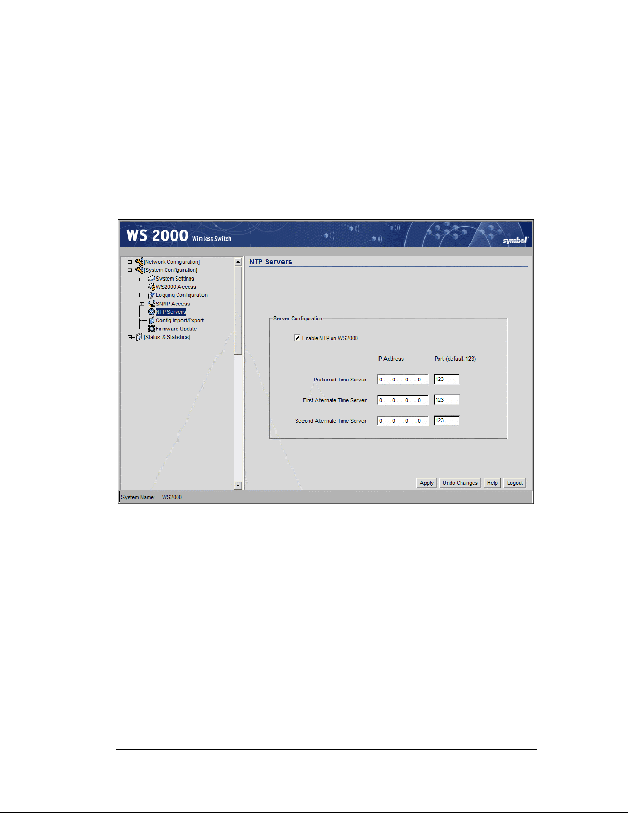
Security—How to Specify a Network Time Protocol (NTP) Server
Security—How to Specify a Network Time Protocol (NTP)
Server
Network Time Protocol (NTP) manages time and clock synchronization in a network
environment. The switch, which acts as an NTP client, periodically synchronizes its clock
with a master clock on an NTP server. Time synchronization is typically optional (although
recommended) for the switch’s network operations; however, for sites using Kerberos
authentication, time synchronization is required. Kerberos must synchronize the clocks of
its Key Distribution Center (KDC) server(s).
1. Select System Configuration --> NTP Servers from the left menu to enable NTP.
The NTP Server screen appears.
2. Select Enable NTP on WS2000 to enable NTP service.
3. Specify a Preferred Time Server, and optionally a First Alternate Time Server
and a Second Alternate Time Server by specifying the IP address and Port for
the time service for each server. The default port is 123. The larger number of NTP
servers specified, provides the greatest assurance of uninterrupted time synchronization.
4. Click the Apply button to save any changes made on this screen. Navigating away
from the current screen without clicking the Apply button will result in the loss of all
changes to this screen.
Copyright © 2004 Symbol Technologies, Inc. All Rights Reserved 60
WS 2000 Wireless Switch: 1.0 Date of last Revision: March 2004
Page 61
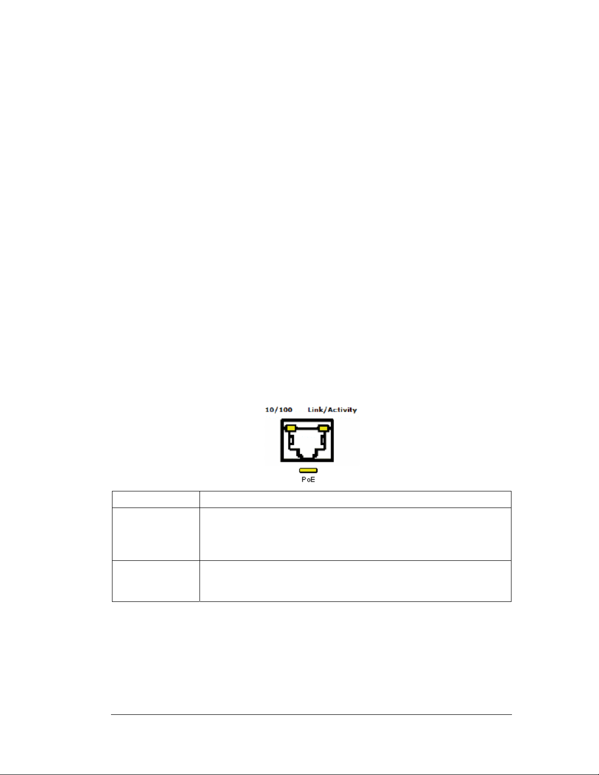
Chapter 5. System Administration
Overview
The WS 2000 Network Management System provides several screens for administering the
switch and monitoring activity on the switch. From the interface the administrator can:
• Change the general system settings, such as the name of the switch and the location of
the switch
• Export or import the switch’s configuration settings
• Find and install firmware updates
• Change the settings for who can access the switch for administration purposes
• Configure how log files are saved
• View system statistics for WAN communication, the subnets, and for the associated
Access Ports
Switch Settings
System Administration
WS 2000 Wireless Switch LED Functions
Each port on the Wireless Switch has either two or three LEDs that indicate the status of the
port. Ports 1-4, which supply 802.3af Power over Ethernet (PoE), have three LEDs. The
remaining two non-powered LAN ports and the WAN port have two LEDs.
Location Description
Upper left LED This LED is present on all ports and indicates the speed of the
transmissions through the port. The LED is on when the transmission
rate is 100 Mbits per second (100BaseT). The light is off when the
transmission rate is 10 Mbits per second.
Upper right LED This LED indicates activity on the port. This light is solid yellow when
a link to a device is made. The light flashes when traffic is being
transferred over the line.
Copyright © 2004 Symbol Technologies, Inc. All Rights Reserved 61
WS 2000 Wireless Switch: 1.0 Date of last Revision: March 2004
Page 62

Location Description
Lower LED This LED is only present on Ports 1-4. These ports provide 802.3af
Power over Ethernet (PoE) support to devices (such as Access
Ports). The LED has several states:
! OFF — A non-power device (or no device) is connected; no
power is being delivered
! GREEN — The switch is delivering 48 volts to the power device
connected to that port.
! RED — There was a valid PoE connection; however, the switch
has detected that the power device is faulty. The red light will
remain until a non-faulty connection is made to the port
Changing the Name of the Switch
When the administrator first logs into the WS 2000 Network Management System, the
System Settings screen appears. One of the fields in this screen is the System Name
field. In this field, the administrator can specify the name of the switch. This name is used
to distinguish the switch from others that are on the network and it is also used to set the
device name in SNMP.
To examine and change the current name for the switch:
System Administration
1. Select System Configuration --> System Settings from the left menu.
2. Find the System Name field and type a string of alphanumeric characters to create a
name.
3. Select the Apply button to save the change.
Copyright © 2004 Symbol Technologies, Inc. All Rights Reserved 62
WS 2000 Wireless Switch: 1.0 Date of last Revision: March 2004
Page 63

System Administration
Change the Location and Country Settings of the WS 2000
When the administrator first logs into the WS 2000 Network Management System, the
System Settings screen appears. One of the fields in this screen is the Country field.
This field is set to the country in which the switch is installed. Setting this field
appropriately ensures compliance with national and local laws concerning electromagnetic
emissions and the power level of Access Port radio transmissions.
To examine and change the location setting for the switch:
1. Select System Configuration --> System Settings from the left menu.
2. Type in a description of the physical location of the switch within your facility into the
Location field.
3. Find the Country field and use the drop down menu to select the correct country from
the list.
4. Click Apply to save changes. The interface will ask you to confirm any changes you
make to the Country selection.
Copyright © 2004 Symbol Technologies, Inc. All Rights Reserved 63
WS 2000 Wireless Switch: 1.0 Date of last Revision: March 2004
Page 64

How to Restart the WS 2000 Wireless Switch
During the normal course of operations, the administrator might need to restart or reset the
switch. For example, changing certain configuration settings can require restarting the
switch for those settings to take effect.
1. Select System Configuration --> System Settings from the left menu.
System Administration
2. Click the Restart WS 2000 button to restart the switch. A second window appears,
asking for confirmation.
3. Select the Restart button. Upon confirming the restart, the switch reboots. Typically,
normal communications with the switch are restored within a minute or two.
Note: Configuration settings are unaffected by the restart process;
however, all cumulative transmission and reception statistics are reset to
zero.
Updating the WS 2000 Wireless Switch’s Firmware
From time to time, Symbol will release updates to the WS 2000 Wireless Switch’s
firmware. These updates will include:
• Information about how to communicate with newly released Access Ports
• Updates for security issues that have been identified
• Fixes to any software problems that have been identified
Copyright © 2004 Symbol Technologies, Inc. All Rights Reserved 64
WS 2000 Wireless Switch: 1.0 Date of last Revision: March 2004
Page 65
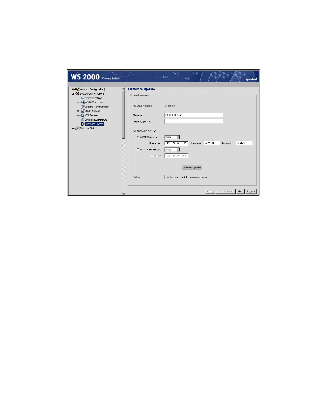
Checking for and Downloading Firmware updates
The switch administrator should check for firmware updates for the WS 2000 Wireless
Switch on a monthly basis, as follows:
1. Select System Configuration --> Firmware Update or Network Configuration
--> System Settings from the left menu.
System Administration
2. Examine the WS 2000 Version field to record the version number of the currently
loaded software. It should be something like 1.02-10.
3. Go to the web site http://www.symbol.com/services/downloads/ and select the link to
the WS 2000 Wireless Switch.
4. Compare the WS 2000 Version with the most recent version listed on the site. All
updates will be listed along with a description of what the update contains.
5. Check to see if an administrator has already downloaded the file. It might already be on
an FTP server at the site. If not, download the update from
http://www.symbol.com/services/downloads/.
Performing the Firmware Update
To perform the update, the update file must be available from an FTP or TFTP site. The
administrator supplies the site information and the WS 2000 Network Management System
will perform FTP/TFTP and the update for the administrator.
1. Save the WS 2000 Network Switch’s current configuration settings (System
Configuration --> Config Import/Export)
2. Select System Configuration --> Firmware Update from the left menu to view the
Firmware Update screen.
3. Specify the name of the update file (such as WS_22343.bin).
4. Specify a folder pathname to the FTP login, if necessary.
5. Select either the FTP or TFTP radio button, as appropriate.
Copyright © 2004 Symbol Technologies, Inc. All Rights Reserved 65
WS 2000 Wireless Switch: 1.0 Date of last Revision: March 2004
Page 66
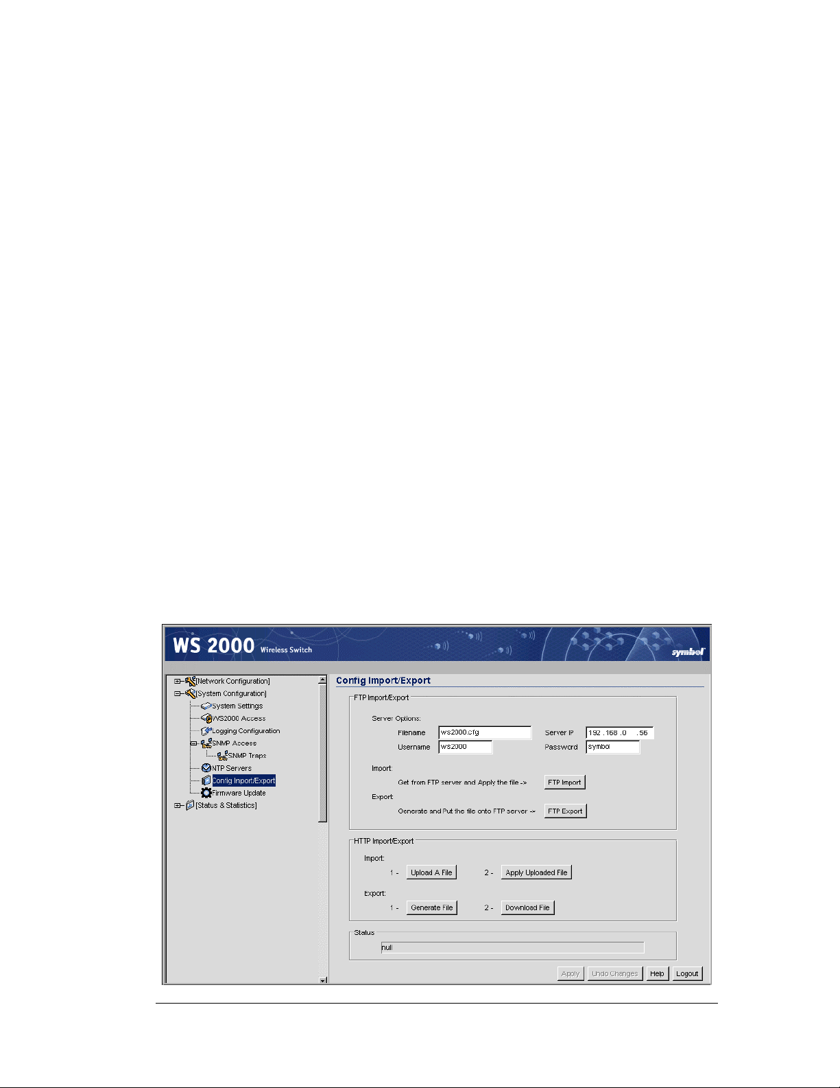
6. Specify whether the site is on the WAN or is on one of the subnets associated with the
switch by selecting the appropriate choice from the drop-down menu to the right of the
radio button.
7. Specify the IP address or domain name of the system that has the update file.
8. Specify a Username and Password that will allow the FTP login and access to the
file.
9. Click the Perform Update button to initiate the firmware update for the switch.
10. After the switch reboots, return to the Firmware Update screen. Read the Status
field to verify that the firmware update completed successfully.
11. Confirm that the wireless switch’s configuration settings are the same as prior to the
update. If not, restore the settings. See “Exporting and Importing Wireless Switch
Settings.”
System Configuration
Exporting and Importing Wireless Switch Settings
All of the configuration settings for the WS 2000 Wireless Switch can be saved to a
configuration file and then either imported back into the same switch or transferred to
another switch. This file-based configuration saving feature provides several benefits:
System Administration
• It can speed the switch setup process significantly at sites using multiple WS 2000
Wireless switches
• It allows an administrator to “backup” the current switch configuration before making
significant changes, before restoring the default configuration, or for precautionary
measures.
Select System Configuration --> Config Import/Export from the left menu to import
or export the switch configuration settings.
Copyright © 2004 Symbol Technologies, Inc. All Rights Reserved 66
WS 2000 Wireless Switch: 1.0 Date of last Revision: March 2004
Page 67

To Import or Export Settings to an FTP Site
Use the following procedure for exporting the switch’s configuration settings.
1. Specify the name of the log Filename to be written to or read from the FTP server.
2. Specify the Server IP address of the FTP server to which the log file will be imported
or exported.
3. Specify the Username to be used when logging in to the FTP server. The user account
must be established on the FTP server that is targeted for importing or exporting file
data.
4. Specify the Password that will allow the user access to the FTP server for the import
or export operation.
5. Click the FTP Import button to import a configuration file from the FTP server with
the given filename and login information. The system will display a confirmation
window indicating that the administrator must log out of the switch after the operation
completes for the changes to take effect.
Click the FTP Export button to export the configuration to a file on the FTP server
with the given filename and login information.
6. After executing the export, check the Status field for messages about the success or
errors in executing the specified operation.
System Administration
To Import Settings to a Local File
1. Click the Upload A File button in the HTTP Import/Export area to specify a
configuration file name that can be specified within the file system.
2. Type in the name of the file, or use the Browse button to find and select the file to
import.
3. Once the upload is successful, click the Apply Uploaded File button to apply the new
configuration to the switch. Check the Status area in the lower portion of the window
for any errors generated during the import process.
To Export Settings to a Local File
1. Click the Generate File button in the HTTP Import/Export area to specify a name for
the configuration file.
2. Type in the name of the file. Use the Browse button to navigate to the desired
directory.
3. Once the name is accepted, click the Download File button to write the configuration
settings to the file.
4. After executing the export, check the Status field for messages about the success or
errors in executing the specified operation.
Copyright © 2004 Symbol Technologies, Inc. All Rights Reserved 67
WS 2000 Wireless Switch: 1.0 Date of last Revision: March 2004
Page 68

How to Restore Default Configuration Settings
Although it should not be necessary during the normal course of operations, the
administrator might need to return to the default configuration settings of the switch. To do
so, see the directions below:
1. Consider saving the current configuration settings. See “Exporting and Importing
Wireless Switch Settings” for directions on how to save the settings.
2. Select System Configuration --> System Settings from the left menu.
System Administration
3. Click the Restore Default Configuration button to restore all factory settings. The
system will display a warning that current settings be lost and ask for confirmation that
the action should be taken.
4. Click the Yes button. Upon confirming the restoration of default settings, the switch
reboots.
5. After the reboot is complete, log into the switch’s configuration screen using “admin”
for the user ID and “symbol” for the password.
If, for some reason, access to the user interface is not possible to restore the factory settings,
a process for restoring the defaults from the command line interface is available.
Copyright © 2004 Symbol Technologies, Inc. All Rights Reserved 68
WS 2000 Wireless Switch: 1.0 Date of last Revision: March 2004
Page 69

System Administration
Restoring Default Configuration Settings Using the Command Line
Interface
Although it should not be necessary during the normal course of operations, the
administrator might need to restore the default configuration settings of the switch. This
procedure is typically performed from the WS 2000 Network Management System user
interface; however, there are circumstances in which the administrator cannot access the
switch through the user interface (for example, if the administrator accidentally disables all
the subnet checkboxes in the WS2000 Access screen). Because of this, there is a process for
restoring the defaults from the command line interface. Follow the directions below.
1. Using a null-modem cable, attach a computer or terminal to the DB-9 serial port on the
front of the switch for direct access to the command-line interface.
2. Using a terminal emulation program, such as HyperTerminal, set up a connection to the
switch through the COM port that is connected to the null-modem cable.
3. Set the properties for the port as indicated below.
Property Value
Bits per second: 19,200
Data bits: 8
Parity: None
Stop bits: 1
Flow control: None
4. When the communications program initiates the connection with the switch, a prompt
to enter manager’s password is displayed. Type in the manager password and then the
ENTER key.
5. When the prompt is displayed type “admin” and ENTER. The interface with then
prompt you for the current admin password. Type in the password and then the ENTER
key. If the login is successful, a prompt is displayed.
6. Type the command “system” followed by the ENTER key.
7. Type the command “config” followed by the ENTER key.
8. Type the command “default” followed by the ENTER key. The default configuration
settings will be restored and the switch will reboot.
After the reboot is complete, you can log into the switch with the standard user interface.
The default IP address for the switch is 192.168. 0.1, and the login information is “admin”
for the user ID and “symbol” is the password.
See Appendix A for a sample configuration file.
Copyright © 2004 Symbol Technologies, Inc. All Rights Reserved 69
WS 2000 Wireless Switch: 1.0 Date of last Revision: March 2004
Page 70

Remote Administration
How to Configure SNMP Traps
The Simple Network Management Protocol (SNMP) facilitates the exchange of
management information between network devices. SNMP allows an administrator to
manage network performance, find and solve network problems, and plan for network
growth. The WS 2000 Wireless Switch includes SNMP management functions for
gathering information from its network components, and communicating that information to
specific users. For more background about SNMP, see SNMP Management Support.
Select System Configuration --> SNMP Access from the left menu to set up SNMP
service.
System Administration
Setting the SNMP Version Configuration
The SNMP Access screen allows the administrator to define SNMP v1/v2c community
definitions and SNMP v3 user definitions. SNMP v1 and v2c provide a strong network
management system, but their security is relatively weak. SNMP v3 provides greatly
enhanced security protocols. SNMP v3 encrypts transmissions and provides authentication
for users generating requests.
Setting Up SNMP v1/v2c Community Definitions
SNMP v1/v2c community definitions allow read-only or read/write access to switchmanagement information, as appropriate. The SNMP community, in this case, includes
users whose IP addresses are specified on the SNMP Access Control subscreen. A readonly community string allows a remote device to retrieve information, while a read/write
community string also allows a remote device to modify settings. Set up a read/write
definition to facilitate full access by the administrator.
Copyright © 2004 Symbol Technologies, Inc. All Rights Reserved 70
WS 2000 Wireless Switch: 1.0 Date of last Revision: March 2004
Page 71

System Administration
1. To create a new community definition, click the Add button in the SNMP v1/v2c
Community Configuration area.
2. Specify a site-appropriate name for the community.
3. Use the OID (Object Identifier) pull-down list to select either All or Custom. If All is
selection, the community has access to all the OIDs (SNMP parameters) in the SNMP
Management Information Base (MIB) file. If Custom is selected, the administrator can
allow access to specific OIDs in the MIB to certain communities.
4. If Custom is selected in the OLD field, type in an OID number into the Custom OID
field. The format is in a numerical dot notation, and valid numbers can be found within
the MIB.
5. Use the Access pull-down list to specify read-only (R) access or read/write (RW)
access for the community. Read-only access allows a remote device to retrieve switch
information, while read/write access also allows a remote device to modify switch
settings.
6. Follow the directions for setting up the Access Control List (below).
Setting Up SNMP v3 Community Definitions
Setting up the v3 user definition is very similar to the v1/v2c community definitions. The
difference is the addition of a user security level and a user password.
1. To create a new SNMP v3 user definition, click the Add button in the SNMP v3 User
Definitions area.
2. Specify a user name in the Username field.
3. Select a security level from the Security pull-down list. Select from the following
choices:
noAuth
AuthNoPriv
AuthPriv
(no authorization) Allows the user to access SNMP without
authorization or encryption
(authorization without privacy) Requires the user to login,
however no encryption is used
(authorization with privacy) Requires the user to login and
encryption is used
4. Use the OID (Object Identifier) pull-down list to select either All or Custom. If All is
selection, the community has access to all the OIDs (SNMP parameters) in the MIB
file. If Custom is selected, the administrator can allow access to specific OIDs in the
MIB to certain communities.
5. If Custom is selected in the OLD field, type in an OID number into the Custom OID
field. The format is in a numerical dot notation, and valid numbers can be found within
the MIB.
6. Specify a password (up to 11 characters) for the user when logging in.
7. Use the Access pull-down list to specify read-only (R) access or read/write (RW)
access for the community. Read-only access allows a remote device to retrieve switch
information, while read/write access also allows a remote device to modify switch
settings.
8. Follow the directions for setting up the Access Control List (below).
Copyright © 2004 Symbol Technologies, Inc. All Rights Reserved 71
WS 2000 Wireless Switch: 1.0 Date of last Revision: March 2004
Page 72
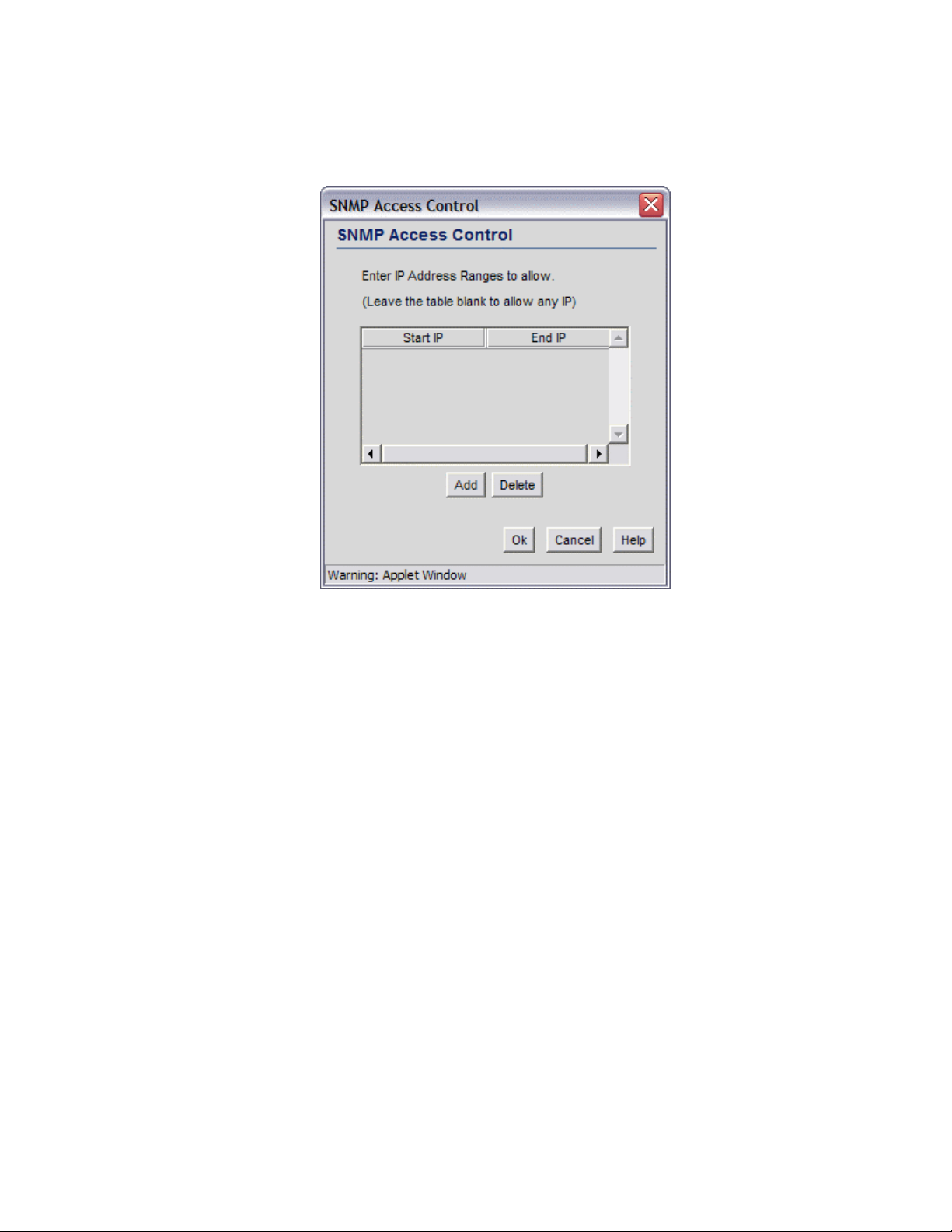
Setting Up the Access Control List
To set up the Access Control list as specified by a range of IP addresses, click the SNMP
Access Control button at the bottom of the SNMP Access screen. The SNMP Access
Control screen appears:
System Administration
1. Click the Add button to create a new entry in the Access Control table.
2. Specify the IP address for the user(s) that have access. Enter an IP address only in the
Starting IP Address column to specify an address for a single SNMP user. Enter
both the Starting IP Address and Ending IP Address columns to specify a range
of addresses for SNMP users.
3. Click OK to save changes and return to the SNMP Access screen.
Setting the Trap Configuration
The final step in setting up SNMP is to specify the types of network events that generate
traps, and who to notify regarding the events. SNMP traps are generated according to
predefined types of network events that are considered important to manage. This
information is asynchronously reported to the switch’s SNMP network-management system
by switch-managed entities. Notification is sent to the responsible individuals whose IP
addresses are listed for trap notification.
1. To set the SNMP traps, select System Configuration --> SNMP Access -->
SNMP Traps from the left menu.
2. Select the type of traps that will generate notification events. To do this, click each of
the four trap buttons in the SNMP Trap Selection area to see all the possible trap
settings.
Copyright © 2004 Symbol Technologies, Inc. All Rights Reserved 72
WS 2000 Wireless Switch: 1.0 Date of last Revision: March 2004
Page 73

System Administration
SNMP Traps MU Traps
AP Traps
3. Check the traps to enable.
Trap
Category
SNMP
Traps
SNMP ACL violation
SNMP
Configuration
Trap Name Generates a Trap when…
Cold Start
authentication
failures
Changes
The switch’s router reinitializes while
transmitting, possibly altering the agent’s
configuration or protocol entity
implementation.
An SNMP client cannot access SNMP
management functions or data due to an
Access Control List (ACL) violation.
An SNMP-capable client is denied access
to the switch’s SNMP management
functions or data. This may result from
incorrect login.
Check this box to generate a trap when
the SNMP access or management
functions are reconfigured.
Copyright © 2004 Symbol Technologies, Inc. All Rights Reserved 73
WS 2000 Wireless Switch: 1.0 Date of last Revision: March 2004
Page 74

System Administration
Trap Trap Name Generates a Trap when…
Category
MU Traps MU associated
An MU becomes associated with one of
the switch’s Wireless Local Area
Networks (WLANs).
MU unassociated
MU denied
association
AP Traps AP adopted
AP unadopted
AP denied adoption
An MU becomes unassociated with (or
gets dropped from) one of the switch’s
WLANs.
Check this box to generate a trap when
an MU cannot associate with the switchmanaged network. A denial of service can
result from an absent or incorrectly
specified MAC address on a WLAN
Security screen.
Any of the switch’s Wireless Local Area
Networks (WLANs) adopts an AP.
Any of the switch’s WLANs unadopts (or
drops) an AP.
Check this box to generate a trap when
any of the switch’s WLANs deny the
adoption of an AP.
4. Click the OK button when done setting traps in a subwindow.
5. Click the Apply button to save the trap settings.
6. It is necessary to tell the switch where to send the notifications. Set the trap
configuration (directions found in one of the following two sections) to indicate where
to send the notifications.
Setting the Trap Configuration for SNMP v1/v2c
To set the trap notification destination for the SNMP v1/v2c servers, add one or more
entries to SNMP v1/v2c Trap Configuration table.
1. Click the Add button to add a new entry to the table.
2. Specify a Destination IP addresses for the systems that will receive notification when
an SNMP trap is generated.
3. Specify a destination User Datagram Protocol (UDP) port for receiving the traps that
are sent by SNMP agents.
UDP offers direct connection for sending and receiving datagrams over an IP network.
4. Specify a Community name that matches one of the community names added on the
SNMP Access screen.
5. Select the appropriate SNMP Version (v1 or v2) from the pull-down list for this
particular SNMP server.
6. Click the Apply button to save the entries.
Copyright © 2004 Symbol Technologies, Inc. All Rights Reserved 74
WS 2000 Wireless Switch: 1.0 Date of last Revision: March 2004
Page 75

Setting the Trap Configuration for SNMP V3
To set the trap notification destination for the SNMP v3 servers, add one or more entries to
SNMP v3 Trap Configuration table.
1. Click the Add button to add a new entry to the table.
2. Specify a Destination IP addresses for the systems that will receive notification when
an SNMP trap is generated.
3. Specify a destination User Datagram Protocol (UDP) port for receiving the traps that
are sent by SNMP agents.
UDP offers direct connection for sending and receiving datagrams over an IP network.
4. Specify a Username that matches one of the user names added on the SNMP Access
screen.
5. Specify a Security level to noAuth (no authorization required), AuthNoPriv
(authorization without encryption), or AuthPriv (authorization with encryption).
6. Specify a password for the user.
Warning: When entering the same username on the SNMP Traps and SNMP Access
screens, the password entered on the SNMP Traps page will overwrite the password
entered on the SNMP Access page. To avoid this problem enter the same password on
both pages.
System Administration
Configure Administrator Access
The WS 2000 Network Management System allows two different users to log in to perform
administration tasks: the switch administrator and the manager.
The switch administrator can change any settings within the WS 2000 Network
Management System. The default login name for the switch administrator is “admin” and
the initial password is “symbol”.
The manager can only view switch statistic (select Statistics & Status). The login name
of the manager is “manager” and the initial password is “symbol”.
To configure which interfaces the administrators can access the user interface or to change
the passwords of the administrators, select System Configuration --> WS 2000
Access from the left menu.
Copyright © 2004 Symbol Technologies, Inc. All Rights Reserved 75
WS 2000 Wireless Switch: 1.0 Date of last Revision: March 2004
Page 76
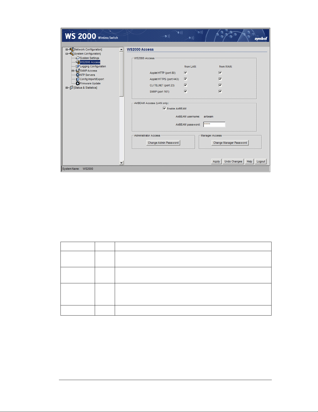
System Administration
Configure Management Access
The WS 2000 Network Management System runs from a standard Web browser. Any
individual on an enabled subnet or over the WAN can access the log screen by specifying
one of the IP addresses associated with the user interface. The WS 2000 Access screen
allows the administrator to restrict access from different locations. By selecting the
appropriate checkboxes, the administrator can allow or disallow specific types of access
from the WAN port or from the LAN subnets.
Choose the types of access to allow by checking the associated checkbox.
Access Port Description
Applet
HTTP
Applet
HTTP
CLI
TELNET
SNMP 161 Allows administration access for an SNMP server.
Note: If all the checkboxes in this section are disabled, the administrator
will not be able to access the switch through the WS2000 Management
System user interface. The only access available is through a direct
serial cable connection from a PC. All commands are given using the
command line interface. If this situation occurs accidentally, you can
restore the switch’s factory settings using the command line interface.
80 Allows access to the WS 2000 Management System through a
standard http web browser communication.
443 Allows access to the WS 2000 Management System through a
https (secure) connection from a web browser.
23 Allows administration access to the wireless switch through
TELNET. Allows the user to access the switch through the
command line interface.
Copyright © 2004 Symbol Technologies, Inc. All Rights Reserved 76
WS 2000 Wireless Switch: 1.0 Date of last Revision: March 2004
Page 77

Setup AirBEAM Software Access
Symbol’s AirBEAM software suite is a comprehensive set of mobility management tools
that maximize the availability, security and effectiveness of a wireless network. The fields
in this section of the screen allow the administrator to enable access from the AirBEAM
software suite and to set the AirBEAM password.
1. To enable AirBEAM access, check the Enable AirBEAM checkbox.
2. Specify a password for AirBEAM software access. Note that the AirBEAM login name
is always “airbeam”.
3. Click the Apply button to save changes.
Changing the Administrator and Manager Passwords
In the lower half of the WS 2000 Access screen, two buttons open sub-screens that allow
the administrator to change either the switch administrator’s or switch manager’s
passwords. For reasons of security, the administrator should change both passwords to
something other than the default, before the system becomes operational.
• Select Change Admin Password to open the screen to change the switch
administrator’s password. Type in the current administrator password and the new
password twice.
System Administration
• Select Change Manager Password to open the screen to change the manager’s
password. Type in the current administrator password and the new manager passwords
twice.
Note: If the administrator does not remember the current password, the
administrator can contact Symbol Technical Support for directions on
how to proceed.
Statistics and Logs
Access Port Statistics
The WS 2000 Network Management System provides a screen that displays basic access
port information, as well as real-time statistics about the activity on each Access Port and its
associated units. To see statistics about a particular Access Port, select Status &
Statistics --> Access Port --> <Access Port Name> from the left menu.
Copyright © 2004 Symbol Technologies, Inc. All Rights Reserved 77
WS 2000 Wireless Switch: 1.0 Date of last Revision: March 2004
Page 78

System Administration
There are four areas on the screen. The Information area shows general information about
the Access Port. The Received and Transmitted areas of the screen display statistics for
the cumulative packets, bytes, and errors received and transmitted through the Access Port.
The Associated Mobile Units section lists the MUs and provides information on specific
MUs that are currently transmitting through the Access Port.
General Access Port Information
Information
Field
Location
HW Address
Adopted by
Channel
Power
Click on the Clear all AP Stats button to clear all the statistics for the selected Access
Port.
Description
The site location of the Access Port (an optional field that the
administrator fills in on the Wireless --> Access Ports --> <Access
Port Name> screen).
The Media Access Control (MAC) address of the Access Port. This
value is typically set at the factory and can be found on the bottom of
the Access Port.
The WLANs that currently adopt this access port (see Network
Configuration --> Wireless for the Access Port Adoption List)
This field indicates the channel for communications between the
Access Port and mobile units. To specify the value, go to the
corresponding Access Port screen.
The power level in milliwatts (mW) for RF signal strength is specified
on the corresponding Access Port screen.
Copyright © 2004 Symbol Technologies, Inc. All Rights Reserved 78
WS 2000 Wireless Switch: 1.0 Date of last Revision: March 2004
Page 79

Received and Transmitted Tables
The Received and Transmitted areas of the screen display statistics for the cumulative
Access Port statistics, since the Access Port was last adopted or the switch was last
rebooted.
Received Field Description
System Administration
RX Packets
RX Bytes
Undecryptable
Packets
Total number of data packets received by the Access Port
Total number of bytes of information received by the Access Port
Total number of data packets that cannot be read due to data
corruption, lack of a proper encryption handshake, and so on
Transmit Field Description
TX Packets
TX Bytes
TX Broadcast
Packets
TX Broadcast
Bytes
Total number of data packets sent by the Access Port
Total number of bytes of information sent by the Access Port
Total number of broadcast packets sent by the Access Port.
Total number of broadcast bytes sent by the Access Port.
Associated Mobile Units
Each Access Port can have up to 32 associated mobile units. These units are listed in the
Mobile Unit Access Control List of the WLAN Security screen (Network Configuration
--> Wireless --> <WLAN Name> --> <WLAN Name> Security.
To see statistics about a particular mobile unit, click the MAC address button for the
mobile unit. A sub-screen appears.
Copyright © 2004 Symbol Technologies, Inc. All Rights Reserved 79
WS 2000 Wireless Switch: 1.0 Date of last Revision: March 2004
Page 80

System Administration
The Received and Transmitted portions of the screen display statistics for the
cumulative packets, bytes, and errors received and transmitted through the access port for
the associated mobile unit since it last gained access to the switch-managed network.
Field Description
WLAN
Association
PSP Mode
Association
Fails
Voice MU
RX Packets
RX Bytes
TX Packets
TX Broadcast
Packets
Indicates the WLAN that is associated with the mobile unit.
Under normal circumstances a switch will terminate a connection with a
mobile unit if it doesn’t exchange packets regularly. Many laptops that
shut down their NIC when there is no network activity. The switch stops
seeing the MU and cuts the connection. When PSP is enabled, the MU
can stop communication with the switch and the connection will remain
active. When the MU starts communicating to the Access Port again the
connection does not need to be reestablished.
The total number of attempts that the Access Port has made to
associate with the mobile unit which have failed.
Indicate whether the mobile unit is a voice-based Mobile unit or not. The
value is yes, if the MY is a voice-based
Total number of data packets received by the Access Port from the
mobile unit
Total number of bytes of information received by the Access Port from
the mobile unit
Total number of data packets sent by the Access Port to the mobile unit
Total number of broadcast packets sent by the Access Port to the
associated mobile unit
TX Bytes
TX Broadcast
Bytes
Undecryptable
Packets
Subnet Statistics
The WS 2000 Network Management System provides a set of screens that allow the
administrator to view real-time statistics for monitoring the switch’s activity. One of those
screens displays statistics for each of the subnets. Selecting Status & Statistics -->
Subnet Stats --> <Subnet Name> Stats from the left menu displays the following
screen.
Total number of bytes sent by the Access Port to the associated mobile
unit
Total number of bytes broadcast by the Access Port to the associated
mobile unit
Total number of bytes that could not be decrypted.
Copyright © 2004 Symbol Technologies, Inc. All Rights Reserved 80
WS 2000 Wireless Switch: 1.0 Date of last Revision: March 2004
Page 81

System Administration
The Information portion of the Subnet Stats screen displays general information about
the subnet.
• The HW address is the Media Access Control (MAC) address of the switch’s WAN
port, which is set at the factory.
• The IP addresses displayed here for the subnet connection are set on the subnet screen
(Network Configuration --> WLAN --> <subnet name> ).
The Received and Transmitted portions of the screen display statistics for the
cumulative packets, bytes, and errors received and transmitted through the WAN interface
since the WAN was last enabled or the switch was last rebooted.
Received Field Description
RX Packets The total number of data packets received over the subnet
RX Bytes The total number of bytes of information received over the subnet
RX Errors
RX Dropped The number of data packets that failed to reach the subnet
RX Overruns
RX Frame The total number of TCP/IP data frame errors received
The total number of errors including dropped data packets, buffer
overruns, and frame errors on inbound traffic
The total number of buffer overruns (when packets are received faster
than the subnet can handle them)
Transmitted
Field
TX Packets The total number of data packets sent over the subnet
TX Bytes The total number of bytes of information sent over the subnet
Copyright © 2004 Symbol Technologies, Inc. All Rights Reserved 81
WS 2000 Wireless Switch: 1.0 Date of last Revision: March 2004
Description
Page 82
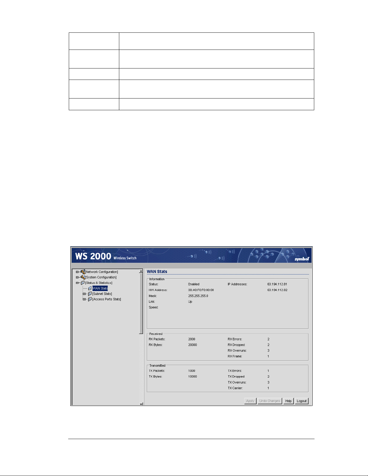
System Administration
Transmitted
Field
TX Errors
TX Dropped The number of data packets that fail to get sent from the subnet
TX Overruns
TX Carrier The total number of TCP/IP data carrier errors received
Interfaces
The interfaces section of the screen displays information about the ports and Access Ports
associated with the subnet (set in Network Configuration --> Subnet --> <Subnet
Name>).
The area shows the status of the port-subnet link and the speed of the connection. The Link
field displays “Up” if the adjacent port is active, and “Down” if the adjacent port is inactive.
The area also shows the status of the port-WLAN associations. In this case, the adopted
Access Ports for each of the associated WLANs are listed.
WAN Statistics
Description
The total number of errors including dropped data packets, buffer
overruns, and carrier errors that fail on outbound traffic
The total number of buffer overruns (when packets are sent faster than
the subnet can handle them)
The WS 2000 Network Management System provides a set of screens that allow the
administrator to view real-time statistics for monitoring the switch’s activity. One of those
screens displays statistics for the Wide Area Network (WAN) port. Selecting Status &
Statistics --> WAN Stats displays the following screen.
Copyright © 2004 Symbol Technologies, Inc. All Rights Reserved 82
WS 2000 Wireless Switch: 1.0 Date of last Revision: March 2004
Page 83

System Administration
The Information portion of the WAN Stats screen displays general information about the
WAN. Much of this information is generated from settings on the WAN screen in the
Network Configuration area.
• The Status field displays “Enabled” if the WAN interface is currently enabled on the
WAN screen (Network Configuration --> WAN). If the WAN interface is disabled
on the WAN screen, the WAN Stats screen does not display connection information
and statistics.
• The HW address is the Media Access Control (MAC) address of the switch’s WAN
port, which is set at the factory.
• The Mask field displays the subnet mask number for the switch’s WAN connection.
This number is set on the WAN screen.
• The Link field displays “Up” if the WAN connection is active, and “Down” if the
WAN connection is interrupted or lost.
• The WAN connection speed is displayed in Megabits per second (Mbps), for example,
100 Mbps.
• The IP addresses displayed here for the WAN connection are set on the WAN screen
(Network Configuration --> WAN).
The Received and Transmitted portions of the screen display statistics for the
cumulative packets, bytes, and errors received and transmitted through the WAN interface,
since the WAN was last enabled or the switch was last rebooted.
Received Field Description
RX Packets The total number of data packets received over the WAN connection
RX Bytes
RX Errors
RX Dropped The number of data packets that failed to reach the WAN interface
RX Overruns
RX Frame The total number of TCP/IP data frame errors received
The total number of bytes of information received over the WAN
connection
The total number of errors including dropped data packets, buffer
overruns, and frame errors on inbound traffic
The total number of buffer overruns (when packets are received
faster than the WAN interface can handle them)
Transmitted
Field
TX Packets The total number of data packets sent over the WAN connection
TX Bytes
TX Errors
Description
The total number of bytes of information sent over the WAN
connection
The total number of errors including dropped data packets, buffer
overruns, and carrier errors that fail on outbound traffic
TX Dropped
Copyright © 2004 Symbol Technologies, Inc. All Rights Reserved 83
WS 2000 Wireless Switch: 1.0 Date of last Revision: March 2004
The number of data packets that fail to get sent from the WAN
interface
Page 84

System Administration
Transmitted
Field
TX Overruns
TX Carrier The total number of TCP/IP data carrier errors received
Description
The total number of buffer overruns (when packets are sent faster
than the WAN interface can handle them)
Setting Up and Viewing the System Log
The WS 2000 Network Management System keeps a log of the events that happen on the
switch. The switch has a modest of amount of memory to store events. If the administrator
wishes to keep a more complete event history, the administrator needs to enable a log
server.
To view the log or set up a log server, select System Configuration --> Logs from the
left menu.
Viewing the Log on the Switch
To save a log of the most recent events that are retained on the switch, click the View
button. The system will display a prompt asking for the administrator password. After the
password has been entered, click the Get File button and a dialogue will be displayed with
buttons to Open or Save the log.txt file. Click Save and specify a location to save the file.
To view the saved log.txt file on a Microsoft Windows based computer use the WordPad
application. Viewing the log file with Notepad, the default text file view on most Windows
based computers, will not properly display the formatting of the log file.
Copyright © 2004 Symbol Technologies, Inc. All Rights Reserved 84
WS 2000 Wireless Switch: 1.0 Date of last Revision: March 2004
Page 85

Setting Up a Log Server
To keep a complete history of the events that are logged by the switch, the administrator
needs to set up an external system log on a server. The server listens for incoming switchgenerated syslog messages on a UDP port (514 by default), and then decodes the messages
into a log file appropriate for viewing and printing. Events are categorized into eight levels
(0 through 7), with the lowest numbers representing the most critical issues.
1. Set the level of the errors to be logged from the Logging Level drop-down list. All
events associated with the selected level and events with levels lower than the selection
will be recorded.
2. Check the Enable logging in to an external syslog server checkbox to enable
logging.
3. Specify the Syslog server IP address for the server that will store the log.
4. Select Apply to save the changes.
5. Select Network Configuration --> Subnet Access. Work through all the
combinations of subnet-to-WAN accesses to ensure that DNS communications are
allowed. (UDP must be enabled to save the log entries.)
System Administration
Copyright © 2004 Symbol Technologies, Inc. All Rights Reserved 85
WS 2000 Wireless Switch: 1.0 Date of last Revision: March 2004
Page 86

Chapter 6. Retail Use Cases
Background
In the past, CCC clothing stores have used POS terminals with a 10BaseT Ethernet
connection to an in-house server. Management has decided to install wireless networking in
the stores. Wireless point of sale (POS) terminals and printers will allow them to be more
flexible with store layout. Wireless handheld terminals for inventory and price lookup will
make inventory faster and more accurate. In some stores, management is adding a cafe with
free wireless Internet access. The hope is that customers will visit more often and stay
longer if their partners can use the Internet while they shop.
The following links show the tasks that the system administrator will carry out to complete
the wireless upgrade.
The Plan
Configuring the System Settings
Configuring the Subnets
The IP Address Plan
Configuring POS Subnet
Configuring the Printer Subnet
Configuring the Cafe Subnet
Retail Use Cases
Configuring the WAN Interface
Configuring NAT
Inspecting the Firewall
Configuring the Access Ports
Configuring the WLANs
Configuring the Cafe WLAN
Configuring the Printer WLAN
Configuring the POS WLAN
Setting Subnet Access
Configuring the Clients
Testing the Connections
Copyright © 2004 Symbol Technologies, Inc. All Rights Reserved 86
WS 2000 Wireless Switch: 1.0 Date of last Revision: March 2004
Page 87

The Plan
Clarisa is the employee assigned to implement the new network in San Jose. She needs
three very different security policies. Wireless security policies are part of a WLAN
configuration, so she will need three different WLANs.
• WLAN #1: Confidential information, such as credit card numbers and customer
• WLAN #2: The wireless printers are difficult to misuse - no keyboards - and the data
• WLAN #3: In the cafe, Clarisa wants an open network - no authentication or encryption.
Retail Use Cases
purchases, will travel over the links to wireless POS terminals. For these, she wants the
strongest security measures possible. The two components of a wireless security policy
are user authentication and data encryption. The corporation has a RADIUS server for
user authentication and it is a logical choice for this application. If the corporation did
not have a RADIUS server, an alternative would have been to install Kerberos on the instore server and use Kerberos user authentication. As for data encryption, WEP is not
secure enough for this traffic. A survey of the wireless POS terminals reveals that they
all support WPA-TKIP, so Clarisa will use WPA-TKIP for data encryption.
stream to them does not include any information that needs strong encryption. On this
WLAN, Clarisa can limit user access by limiting connections to just those devices have
their MAC addresses entered in the switch. The data will be WEP encrypted.
She believes that otherwise the support problems will be too difficult. But management
wants to be absolutely certain that users of the cafe net cannot get access to the store
computers or POS terminals. The WS 2000 allows the administrator to restrict access
from one subnet to another, so Clarisa will create a subnet that is just for WLAN #3, and
then restrict access from that subnet to the other subnets.
This plan covers all of the wireless devices — the POS terminals, the printers, and the
customer laptops — except the wireless handheld terminals. Clarisa decides to put them on
the WLAN with the POS terminals.
There are also some conventional, 100baseT wired devices to consider. There is the store
server and two wired POS terminals. Clarisa will put all of these on the 100baseT ports on
the WS 2000.
To keep things simple, Clarisa decides to define one subnet for each WLAN and assign one
Access Port to each WLAN. The wired devices will be part of the POS subnet.
The WS 2000 will connect to the Internet through a DSL line.
Copyright © 2004 Symbol Technologies, Inc. All Rights Reserved 87
WS 2000 Wireless Switch: 1.0 Date of last Revision: March 2004
Page 88
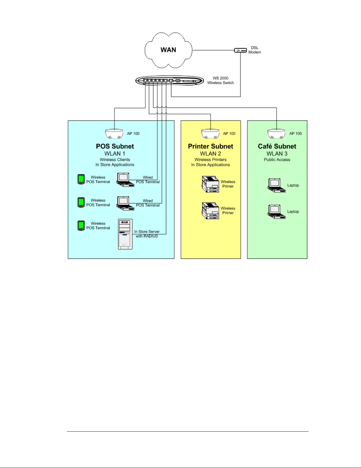
Retail Use Cases
Configuring the System Settings
Contacting the Wireless Switch
Clarisa sets up a direct network link between her laptop and the switch, plugging the cable
into one of the local, non-WAN, ports. The switch defaults to having all the LAN ports on
the first subnet and that subnet having an IP address of 192.168.0.1. So, as far as this
connection is concerned, the switch comes up with an initial IP address of 192.168.0.1. She
sets her laptop to have an IP address of 192.168.0.2 and a netmask of 255.255.255.0. She
also sets the gateway IP address to be 192.168.0.1, the WS 2000’s IP address.
Copyright © 2004 Symbol Technologies, Inc. All Rights Reserved 88
WS 2000 Wireless Switch: 1.0 Date of last Revision: March 2004
Page 89
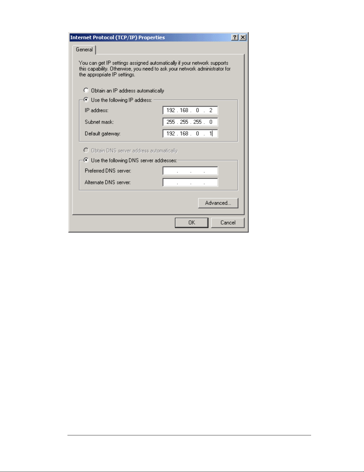
Retail Use Cases
Clarisa starts her web browser and enters “http://192.168.0.1/” as the URL. The WS 2000
sends a login page to her browser.
She logs in using “admin” for the username and “symbol” as the password.
Entering the Basic System Settings
Clarisa selects System Settings in the left menu, located under the System Configuration
heading.
The System Name is used to distinguish between WS 2000 switches for remote
configuration. She gives the switch a descriptive name, “SanJose-1”. This name will appear
in the footer for subsequent configuration windows for the switch. She does not need the
name now, while she is in San Jose. But later, when she returns to corporate headquarters
and wants to log into several switches remotely, it will help her to know which switch she is
working on. She also enters a slightly longer description on the System Location field.
She enters her email address into the Admin Email Address box. CCC uses an SNMP
manager that has the capability of monitoring network devices and sending email to the
manager of a device that is in an unusual state. This is the email address that will be
supplied to that SNMP manager for this switch.
She sets the country to “United States - US”. Different countries have different regulations
for the use of these radio frequencies. Setting the location configures the switch to use only
the channels, frequencies, and power levels that are legal for that country.
Clarisa clicks the Apply button to save her changes.
Copyright © 2004 Symbol Technologies, Inc. All Rights Reserved 89
WS 2000 Wireless Switch: 1.0 Date of last Revision: March 2004
Page 90

Retail Use Cases
Setting Access Control
In the WS 2000 Access screen, Clarisa controls which network interfaces can be used to
reconfigure the WS 2000 switch. She is currently using HTTP access on port 80 over the
LAN, so she leaves that on. She wants to be able to manage the switch from corporate
headquarters, but she does not want to leave the standard HTTP port, port 80, open over the
WAN. She elects to leave port 443 open over the WAN instead. She knows she will want to
monitor the switch from her SNMP system at corporate, so she leaves SNMP WAN access
on.
AirBEAM is a Symbol Technology software system designed to simplify maintenance of
wireless devices. CCC clothing recently purchased an AirBEAM license as part of a major
commitment to Symbol Technology wireless bar code scanners for inventory. Clarisa would
like to integrate the WS 2000 into the AirBEAM management system and she leaves
AirBEAM access on. Clarissa changes the passwords for Administrator Access and for
Manager Access to something relatively secure, something with letters, numbers, and
punctuation marks in it.
Copyright © 2004 Symbol Technologies, Inc. All Rights Reserved 90
WS 2000 Wireless Switch: 1.0 Date of last Revision: March 2004
Page 91
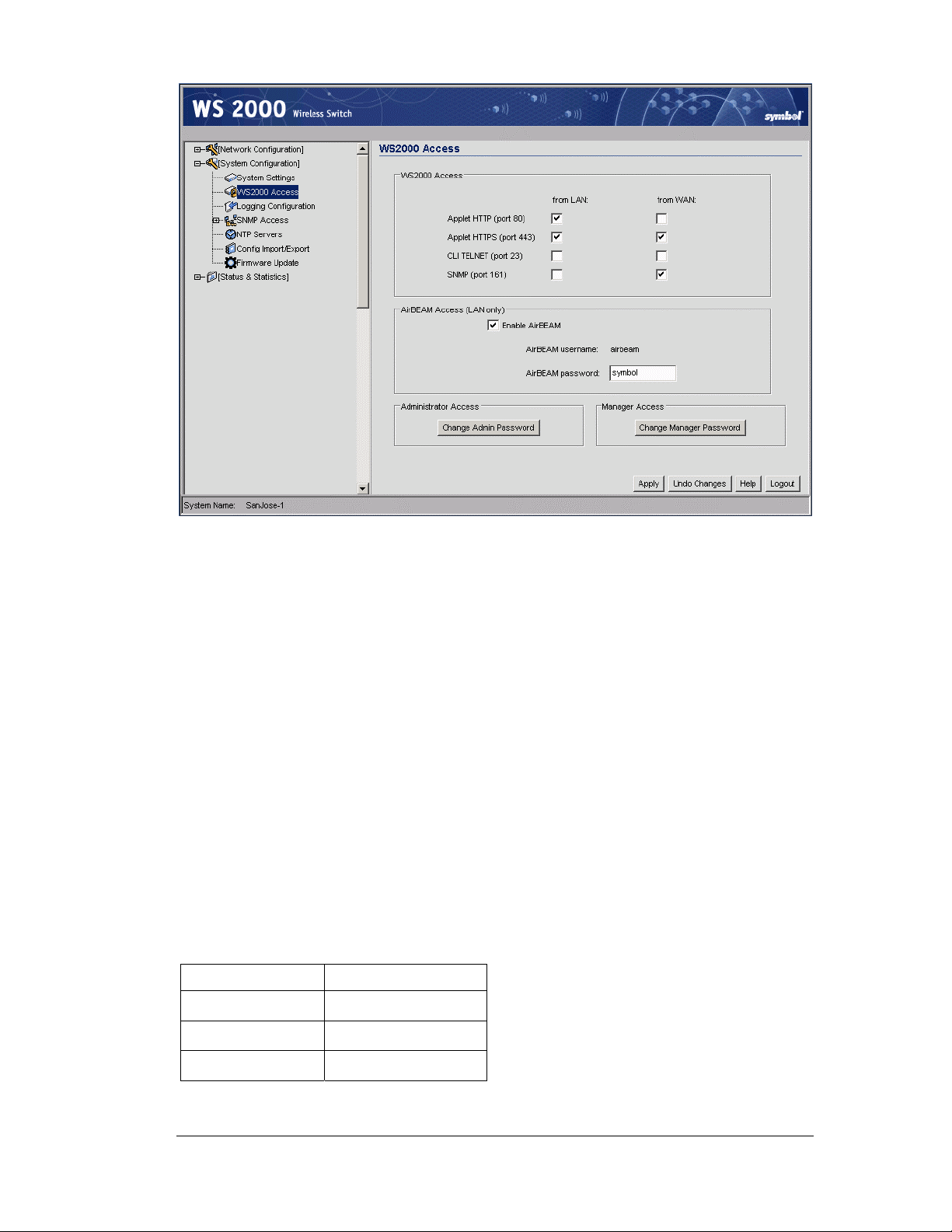
Clarisa clicks the Apply button to save her changes.
Retail Use Cases
Clarisa leaves the rest of the System Configuration screens for now, moves to the left menu,
and clicks the “+” to the left of Network Configuration so that she can begin to define the
subnets.
Configuring the Subnets
The IP Address Plan
Now Clarisa needs to name and define the subnets. The subnet menu items are under the
LAN item in Network Configuration in the WS 2000 left menu. The subnets can be
renamed, assigned an IP address, and have ports associated with them. Before she can do
this, however, Clarisa needs to plan how she is going to assign IP addresses to the subnets
and the devices on them.
Clarisa only has one IP address from corporate for this store. She will use network address
translation (NAT) for all of the devices, making request from those devices look to the
outside world as if they came from the single static IP address that she has. For the devices,
she plans to use IP numbers from the range 192.168.*.*, because IP addresses in that range
are designated for internal use only.
She will assign them as follows:
Subnet IP Address Range
192.168.0.*** POS subnet
192.168.1.*** Printer subnet
192.168.2.*** Cafe Subnet
Copyright © 2004 Symbol Technologies, Inc. All Rights Reserved 91
WS 2000 Wireless Switch: 1.0 Date of last Revision: March 2004
Page 92
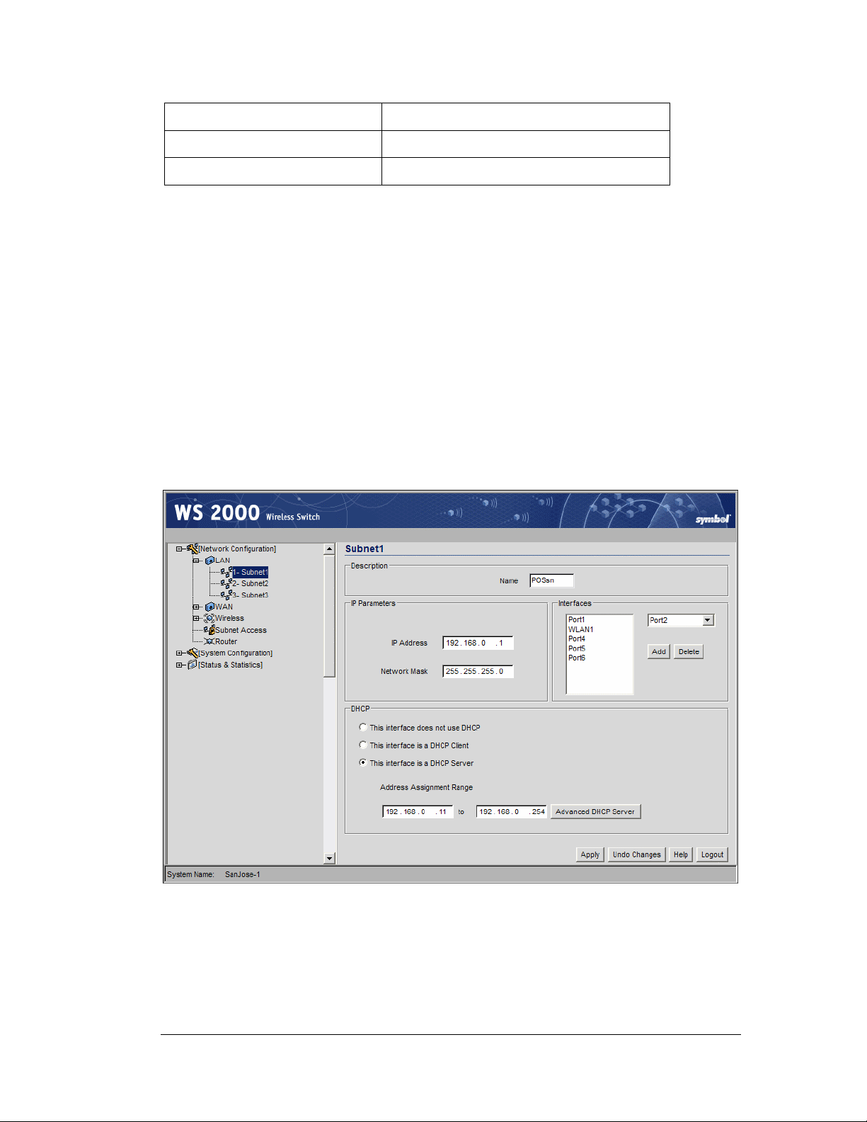
And for each subnet:
192.168.**.1 The subnet itself
192.168.**.2 to 192.168.**.10 Static IP addresses
192.168.**.11 to 192.168.**.254 DHCP-supplied IP addresses on the subnet
With this plan, she can begin to configure the individual subnets
Configuring POS Subnet
Clarisa selects the first subnet from the LAN menu items in the left menu.
Clarisa renames this subnet “POSsn”, and then gives it an IP address of 192.168.0.1 and a
subnet mask of 255.255.255.0. The devices on this subnet are:
• Everything on the POS WLAN: wireless POS terminals and wireless handheld terminals
• One wired POS terminal on port 4 and one on port 5
• One in-store server on port 6
Using the Interfaces section of the screen on the right, she associates the first WLAN with
this subnet, as well as Ports 1 (the one the POS WLAN is plugged into), 4 and 5 (the wired
POS terminals), and 6 (the server). She activates the DHCP server and gives it an IP address
range of 192.168.0.11 to 192.168.0.254.
Retail Use Cases
After she enters the Address Assignment Range, Clarisa clicks Advanced DHCP
Server.
Copyright © 2004 Symbol Technologies, Inc. All Rights Reserved 92
WS 2000 Wireless Switch: 1.0 Date of last Revision: March 2004
Page 93

Retail Use Cases
The Default Gateway is already set to the subnet address. This is the IP address to which
the DHCP clients on this subnet will forward their outbound traffic. Clarisa fills in the DNS
Server addresses that corporate has specified. This will also be supplied to the DHCP
clients. The DHCP Lease Time is the time an IP address will remain assigned to a client
after there is no more activity. She leave it at the default and clicks Ok to save her changes.
Then, in the subnet screen, she clicks Apply to save her overall changes.
Now she will configure the printer subnet.
Configuring the Printer Subnet
Clarisa selects the second subnet from the list of LAN menu items in the left menu.
She renames this subnet “Printsn”, and then gives it an IP address of 192.168.1.1 and a
subnet mask of 255.255.255.0. The only devices on this subnet are the wireless printers.
Using the Interfaces section of the screen, she associates the second WLAN with this
subnet. She activates the DHCP server with an IP address range of 192.168.1.11 to
192.168.1.254.
Copyright © 2004 Symbol Technologies, Inc. All Rights Reserved 93
WS 2000 Wireless Switch: 1.0 Date of last Revision: March 2004
Page 94

Retail Use Cases
After entering the Address Assignment Range, Clarisa clicks Advanced DHCP
Server.
Copyright © 2004 Symbol Technologies, Inc. All Rights Reserved 94
WS 2000 Wireless Switch: 1.0 Date of last Revision: March 2004
Page 95

Retail Use Cases
Clarisa enters the DNS server IP addresses and leaves the Default Gateway and DHCP
Lease Time at their defaults.
She clicks Ok in the Advanced DHCP Server window and then Apply in the Subnet
window to save her changes.
Now Clarisa will configure the Cafe subnet.
Configuring the Cafe Subnet
Clarisa selects the third subnet in the LAN menu list under Network Configuration in the
left menu.
She then renames this subnet “Cafesn” and gives it the IP address 192.168.2.1 and a subnet
mask of 255.255.255.0. The only devices on this subnet are the customer’s laptops in the
cafe.
Using the Interfaces section of the screen, she associates the third WLAN with this subnet,
and activates the DHCP server with an IP address range of 192.168.2.11 to 192.168.2.254.
Copyright © 2004 Symbol Technologies, Inc. All Rights Reserved 95
WS 2000 Wireless Switch: 1.0 Date of last Revision: March 2004
Page 96
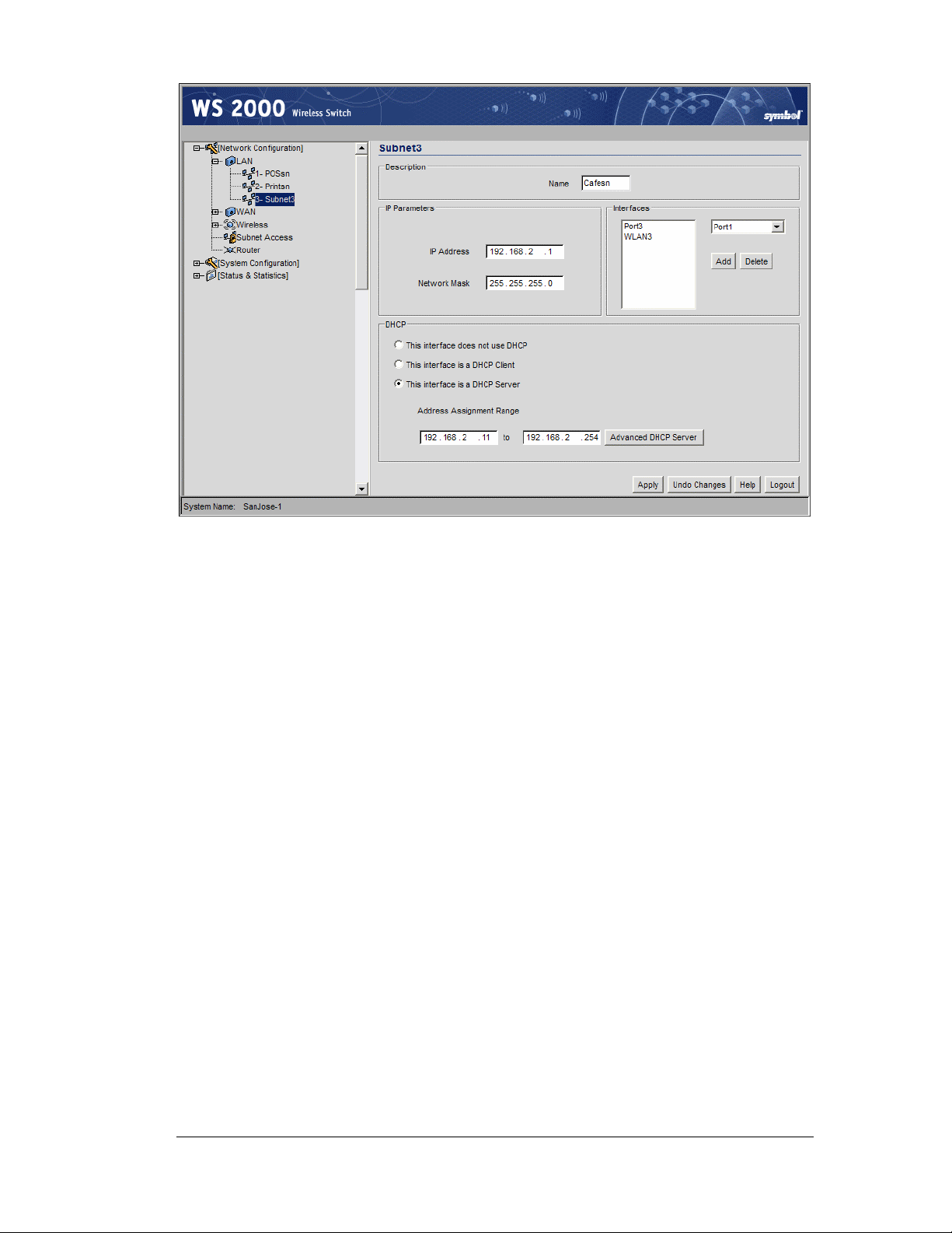
Retail Use Cases
Clarisa clicks Advanced DHCP Server and enters the DNS server IP addresses. The
Default Gateway is fine. However, Clarisa expects the cafe patrons to come and go
frequently, so she reduces the IP address lease time to 1800 seconds. This means that a
DHCP client mobile unit will give up its IP address if it is inactive on the network for more
than half an hour. This seems about right for the usage patterns that she expects for the cafe.
If she gets complaints, she will bump it to an hour.
Copyright © 2004 Symbol Technologies, Inc. All Rights Reserved 96
WS 2000 Wireless Switch: 1.0 Date of last Revision: March 2004
Page 97
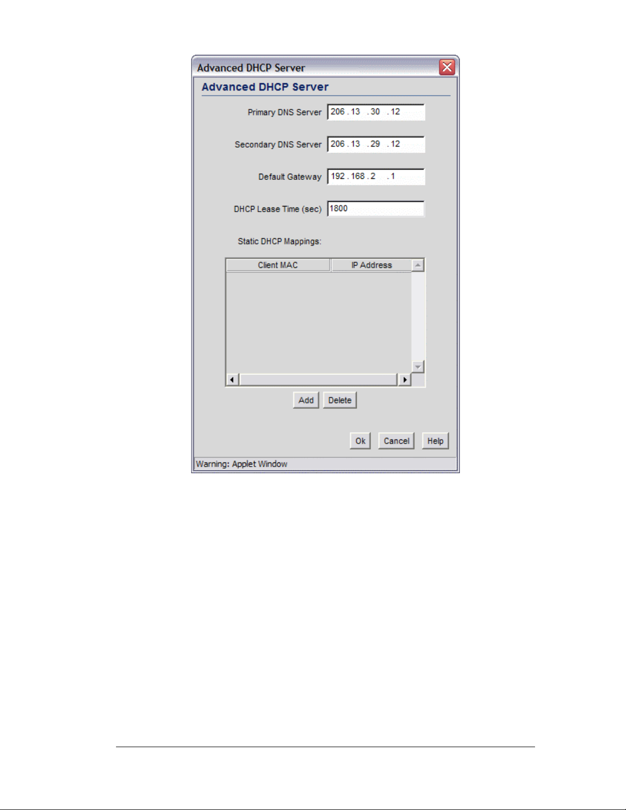
Retail Use Cases
Clarisa clicks the Ok button in the Advanced DHCP Server window, then on the Apply
button in the subnet screen to save her choices. The subnets are now configured.
Next Clarisa configures the WAN interface.
Configuring the WAN Interface
Now Clarisa selects the WAN node in the left menu. Here she enters the static IP address
assigned to this store by CCC corporate. She also enters the other information supplied to
her by corporate: the gateway IP address, the subnet mask, and the DNS server IP
addresses. She is connecting by a DSL modem, but because she has a static IP address, her
Internet service provider (ISP) does not require PPP-over-Ethernet connection information.
If her ISP required PPPoE account information, she would have entered that information in
the PPP-over-Ethernet section of the screen.
Copyright © 2004 Symbol Technologies, Inc. All Rights Reserved 97
WS 2000 Wireless Switch: 1.0 Date of last Revision: March 2004
Page 98
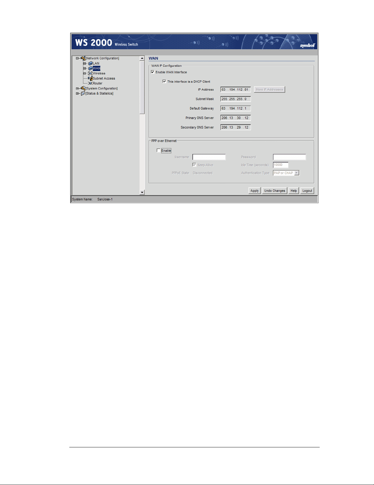
Retail Use Cases
If corporate had not paid their ISP for a static IP address for each store, she would have
selected the This interface is a DHCP Client option and the WAN configuration
information would have been assigned by the ISP each time they connected to the Internet.
Clarisa clicks the Apply button to save her changes.
Configuring Network Address Translation (NAT)
Clarisa has only one public IP address for the whole store. She will use network address
translation to make all request from the internal IP addresses to appear as if they came from
the single public IP address.
She selects the NAT node under the WAN item in the left menu. The screen shows all IP
addresses assigned to the switch in the WAN interface configuration step. In this case, there
is one IP address shown. She selects 1 to Many from the NAT Type menu to the right of
the IP address.
Copyright © 2004 Symbol Technologies, Inc. All Rights Reserved 98
WS 2000 Wireless Switch: 1.0 Date of last Revision: March 2004
Page 99

Retail Use Cases
After she makes this selection a new button appears, labeled 1 to Many Mappings. She
selects the 1 to Many Mappings button:
If Clarisa had more than one static IP address, she would have been able to assign several to
the WAN interface. This screen is used to choose how the internal IP addresses on each
subnet translated into the selection of external IP addresses. However, she has only one
external IP address. All requests from any IP address on the store network are translated
into a request using the single public IP address for the store.
Clarisa clicks the Ok button to confirm the Outbound Mappings and then clicks the Apply
button in the main screen to confirm the NAT choices and save her choices on the switch.
Copyright © 2004 Symbol Technologies, Inc. All Rights Reserved 99
WS 2000 Wireless Switch: 1.0 Date of last Revision: March 2004
Page 100

Inspecting the Firewall
Clarisa selects the Firewall item in the left menu. Each of the checkbox items represents a
type of attack the WS 2000 can filter out. She checks to see that all of the options are
enabled.
Retail Use Cases
Clarisa clicks the Apply button to confirm that all attacks listed will be filtered.
Configuring the Access Ports
So far, Clarisa has been operating with the WS 2000 connected only to her laptop. To
configure the Access Ports, she will need to connect them to the switch. She plans to use
switch ports as follows:
Switch Port Connected to
Port 1 Access port for the POS WLAN
Port 2 Access port for the Printer WLAN
Port 3 Access port for the Cafe WLAN
Port 4 Wired POS terminal #1
Port 5 Wired POS terminal #1
Port 6 In-store server
Setting Access Port Defaults
The WS 2000 allows the user to specify the default settings for Access Ports. Clarisa
expands the Access Ports node in the left menu and selects the 11b Defaults node. Clarisa
has only 802.11b Access Ports.
Copyright © 2004 Symbol Technologies, Inc. All Rights Reserved 100
WS 2000 Wireless Switch: 1.0 Date of last Revision: March 2004
 Loading...