

Page 1
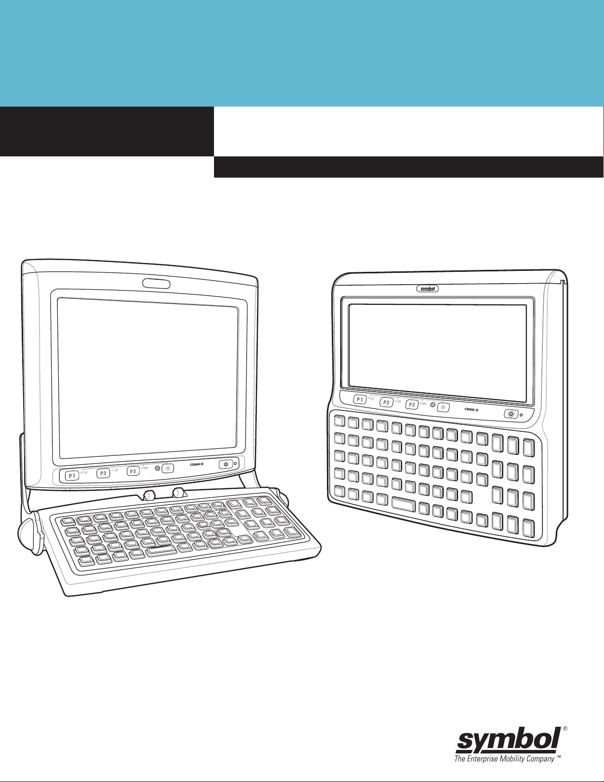
VC5090 Vehicle Computer
Product Reference Guide
Page 2

Page 3

VC5090 Vehicle Computer
Product Reference Guide
72E-76347-01
Revision A
May 2006
Page 4

© 2006 by Symbol Technologies, Inc. All rights reserved.
No part of this publication may be reproduced or used in any form, or by any electrical or mechanical means, without
permission in writing from Symbol. This includes electronic or mechanical means, such as photocopying, recording, or
information storage and retrieval systems. The material in this manual is subject to change without notice.
The software is provided strictly on an “as is” basis. All software, including firmware, furnished to the user is on a
licensed basis. Symbol grants to the user a non-transferable and non-exclusive license to use each software or
firmware program delivered hereunder (licensed program). Except as noted below, such license may not be assigned,
sublicensed, or otherwise transferred by the user without prior written consent of Symbol. No right to copy a licensed
program in whole or in part is granted, except as permitted under copyright law. The user shall not modify, merge, or
incorporate any form or portion of a licensed program with other program material, create a derivative work from a
licensed program, or use a licensed program in a network without written permission from Symbol. The user agrees to
maintain Symbol’s copyright notice on the licensed programs delivered hereunder, and to include the same on any
authorized copies it makes, in whole or in part. The user agrees not to decompile, disassemble, decode, or reverse
engineer any licensed program delivered to the user or any portion thereof.
Symbol reserves the right to make changes to any software or product to improve reliability, function, or design.
Symbol does not assume any product liability arising out of, or in connection with, the application or use of any product,
circuit, or application described herein.
No license is granted, either expressly or by implication, estoppel, or otherwise under any Symbol Technologies, Inc.,
intellectual property rights. An implied license only exists for equipment, circuits, and subsystems contained in Symbol
products.
Symbol and the Symbol logo are registered trademarks of Symbol Technologies, Inc. Bluetooth is a registered
trademark of Bluetooth SIG. Microsoft, Windows and ActiveSync are either registered trademarks or trademarks of
Microsoft Corporation. Other product names mentioned in this manual may be trademarks or registered trademarks of
their respective companies and are hereby acknowledged.
Symbol Technologies, Inc.
One Symbol Plaza
Holtsville, New York 11742-1300
http://www.symbol.com
Patents
This product is covered by one or more of the patents listed on the web site: http://www.symbol.com/patents.
Warranty
Subject to the terms of Symbol’s hardware warranty statement, the VC5090 Vehicle Computer products are warranted
against defects in workmanship and materials for a period of one year from the date of shipment. For the complete
Symbol hardware product warranty statement, go to: http://www.symbol.com/warranty.
Page 5

Revision History
Changes to the original manual are listed below:
Change Date Description
-01 Rev A 5/31/06 Initial release.
Page 6

Page 7

Table of Contents
Patents........................................................................................................................... ii
Warranty ........................................................................................................................ ii
Revision History ............................................................................................................. iii
About This Guide
Introduction .................................................................................................................... v
Documentation Set .................................................................................................. v
Configurations................................................................................................................ v
Chapter Descriptions ..................................................................................................... vi
Notational Conventions.................................................................................................. vi
Related Documents and Software ................................................................................. vii
Service Information ........................................................................................................ vii
Returning the Vehicle Computer for Service............................................................ vii
Chapter 1: Getting Started
Introduction ................................................................................................................... 1-1
Unpacking the VC5090 ................................................................................................. 1-1
Features ........................................................................................................................ 1-2
Accessories ................................................................................................................... 1-4
Peripherals .................................................................................................................... 1-6
Getting Started .............................................................................................................. 1-7
Installing the Desiccant Bag .................................................................................... 1-7
Installing the Vehicle Computer .............................................................................. 1-8
Charging the Memory Backup Battery .................................................................... 1-8
Starting the Vehicle Computer ................................................................................ 1-8
Chapter 2: Installation
Introduction ................................................................................................................... 2-1
Installing Mounting Brackets ......................................................................................... 2-2
Installing the VC5090 in a Forklift ................................................................................. 2-3
Positioning the Vehicle Computer ........................................................................... 2-3
Mounting the Vehicle Computer............................................................................... 2-5
Mounting Bracket Template .............................................................................. 2-5
Mounting onto an Over-Head Cross-Beam Example ........................................ 2-6
Mounting onto an Over-Head Cage Example ................................................... 2-7
Page 8

2 VC5090 Vehicle Computer Product Reference Guide
Mounting on a Dashboard or Horizontal Surface Example ............................... 2-8
Routing Electrical Cables .................................................................................. 2-8
12-24 Volt Gasoline, Diesel, or Propane Forklifts ............................................. 2-9
Electric Forklifts Up to 60 Volts ......................................................................... 2-9
Connecting the Power Cable ............................................................................ 2-10
Removing Power to the Vehicle Computer ............................................................. 2-11
Installing the VC5090 on a Wall or Desktop .................................................................. 2-12
Mounting the Bracket on a Wall .............................................................................. 2-12
Mounting the Bracket on a Desktop......................................................................... 2-13
Connecting the Vehicle Computer to AC Power...................................................... 2-14
Installing the Optional Keyboard.................................................................................... 2-15
Adjusting the Keyboard ........................................................................................... 2-17
Installing a Scanner ....................................................................................................... 2-19
Connecting a Serial Scanner .................................................................................. 2-19
Connecting a USB Scanner .................................................................................... 2-19
Scanner Setup ........................................................................................................ 2-20
Enable/Disable the Scanner ................................................................................... 2-22
Displaying Bar Code Data ....................................................................................... 2-22
Pairing Bluetooth Scanner and Cradle .................................................................... 2-22
Installing the Uninterruptable Power Supply.................................................................. 2-23
Installing a Secure Digital Card ..................................................................................... 2-25
Installing a External Antenna ......................................................................................... 2-27
Installing the Vehicle In-Motion Detector ...................................................................... 2-28
Switches .................................................................................................................. 2-28
Cable Installation .................................................................................................... 2-29
Over-Ride ................................................................................................................ 2-32
Connecting Accessories ............................................................................................... 2-33
Connecting an External Speaker to the Vehicle Computer .......................................... 2-33
Chapter 3: Operating the VC5090
Introduction ................................................................................................................... 3-1
Quick Access Panel ...................................................................................................... 3-1
Power Button .......................................................................................................... 3-1
Power LED .............................................................................................................. 3-1
COMM LED ............................................................................................................. 3-2
Backlight Control Button ......................................................................................... 3-3
Programmable (“P”) Keys ....................................................................................... 3-3
Launch Application ............................................................................................ 3-4
Simulate KeyPress ............................................................................................ 3-4
Play Key Sequence ........................................................................................... 3-5
Using the Keyboard ...................................................................................................... 3-5
Keyboard Functionality ........................................................................................... 3-5
Soft Keyboards ....................................................................................................... 3-6
Adjusting the Brightness ............................................................................................... 3-8
Controlling Screen Brightness ................................................................................ 3-8
Controlling Keyboard Backlight ............................................................................... 3-8
Adjusting the Volume .................................................................................................... 3-9
Status Icons .................................................................................................................. 3-9
Page 9

Table of Contents 3
Using a Headset ............................................................................................................ 3-11
Resetting the Vehicle Computer ................................................................................... 3-11
Performing a Warm Boot ........................................................................................ 3-11
Performing a Cold Boot ........................................................................................... 3-11
Methods of Suspension .......................................................................................... 3-12
Critical Suspension ................................................................................................. 3-12
Waking the Vehicle Computer ................................................................................ 3-12
Calibrating the Screen ................................................................................................... 3-13
Using the Display .................................................................................................... 3-13
Using the Keyboard ................................................................................................ 3-14
Checking Battery Status ................................................................................................ 3-17
Ignition Sensing ............................................................................................................ 3-17
Chapter 4: Wireless Applications
Introduction ................................................................................................................... 4-1
Signal Strength Icon ...................................................................................................... 4-2
Turning the WLAN Radio On and Off ........................................................................... 4-2
Find WLANs Application ............................................................................................... 4-3
Profile Editor Wizard ..................................................................................................... 4-4
Profile ID ................................................................................................................. 4-4
Operating Mode ...................................................................................................... 4-5
Ad-Hoc .................................................................................................................... 4-6
Authentication ......................................................................................................... 4-6
Tunneled Authentication ......................................................................................... 4-7
User Certificate Selection ....................................................................................... 4-9
User Certificate Installation ............................................................................... 4-9
Server Certificate Selection .................................................................................... 4-10
Credential Cache Options ....................................................................................... 4-11
Password ................................................................................................................. 4-14
Advanced Identity ................................................................................................... 4-14
Encryption ............................................................................................................... 4-15
Key Entry Page ................................................................................................. 4-16
Passkey Dialog ................................................................................................. 4-16
IP Mode ................................................................................................................... 4-17
IP Address Entry ..................................................................................................... 4-17
Transmit Power ....................................................................................................... 4-19
Battery Usage ......................................................................................................... 4-20
Manage Profiles Application .................................................................................... 4-21
Changing Profiles .............................................................................................. 4-22
Editing a Profile ................................................................................................. 4-22
Creating a New Profile ...................................................................................... 4-22
Deleting a Profile ............................................................................................... 4-23
Ordering Profiles ............................................................................................... 4-23
Export a Profile .................................................................................................. 4-23
Wireless Status Application .......................................................................................... 4-24
Signal Strength Window .......................................................................................... 4-24
Current Profile Window ........................................................................................... 4-26
IPv4 Status Window ................................................................................................ 4-27
Page 10

4 VC5090 Vehicle Computer Product Reference Guide
Wireless Log Window ............................................................................................. 4-28
Saving a Log ..................................................................................................... 4-28
Clearing the Log ................................................................................................ 4-28
Versions Window .................................................................................................... 4-29
Wireless Diagnostics Application .................................................................................. 4-30
ICMP Ping Window ................................................................................................. 4-30
Trace Route Window .............................................................................................. 4-31
Known APs Window ................................................................................................ 4-32
Options ......................................................................................................................... 4-32
Operating Mode Filtering ........................................................................................ 4-33
Regulatory Options ................................................................................................. 4-33
Band Selection ........................................................................................................ 4-34
System Options ....................................................................................................... 4-34
Change Password ................................................................................................... 4-35
Export ...................................................................................................................... 4-36
Cold Boot Persistence .................................................................................................. 4-37
Registry Settings ........................................................................................................... 4-37
Log On/Off Application .................................................................................................. 4-38
User Already Logged In .......................................................................................... 4-38
No User Logged In .................................................................................................. 4-38
Chapter 5: Using the Bluetooth
Introduction ................................................................................................................... 5-1
Adaptive Frequency Hopping ....................................................................................... 5-1
Security ......................................................................................................................... 5-2
Turning the Bluetooth Radio Mode On and Off ............................................................ 5-2
Disabling Bluetooth ................................................................................................. 5-2
Enabling Bluetooth .................................................................................................. 5-3
Bluetooth Power States .......................................................................................... 5-3
Cold Boot .......................................................................................................... 5-3
Warm Boot ........................................................................................................ 5-3
Suspend ............................................................................................................ 5-3
Resume ............................................................................................................. 5-3
Modes ........................................................................................................................... 5-3
Wizard Mode ........................................................................................................... 5-3
Explorer Mode ......................................................................................................... 5-6
Discovering Bluetooth Device(s) ................................................................................... 5-6
Bonding with Discovered Device(s) .................................................................. 5-7
Renaming a Bonded Device ............................................................................. 5-9
Deleting a Bonded Device ................................................................................ 5-10
Accepting a Bond .............................................................................................. 5-10
Discovering Services .................................................................................................... 5-11
File Transfer Services ............................................................................................. 5-12
Create New File or Folder ................................................................................. 5-13
Delete File ......................................................................................................... 5-13
Get File ............................................................................................................. 5-13
Put File .............................................................................................................. 5-14
Page 11

Table of Contents 5
Connect to Internet Using Access Point ................................................................. 5-14
Headset Services .................................................................................................... 5-14
Serial Port Services ................................................................................................ 5-15
Bluetooth Settings ......................................................................................................... 5-16
Device Info Tab ....................................................................................................... 5-16
Services Tab ........................................................................................................... 5-16
File Transfer Service ......................................................................................... 5-17
Personal Area Networking Service ................................................................... 5-18
Serial Port Service ............................................................................................ 5-19
Headset Service ................................................................................................ 5-19
Security Tab ............................................................................................................ 5-20
Discovery Tab ......................................................................................................... 5-20
Virtual COM Port Tab .............................................................................................. 5-21
Miscellaneous Tab .................................................................................................. 5-21
Chapter 6: ActiveSync
Introduction ................................................................................................................... 6-1
Installing ActiveSync ..................................................................................................... 6-1
Mobile Computer Setup ................................................................................................ 6-1
Setting Up an ActiveSync Connection on the Host Computer ...................................... 6-2
Setting up a Partnership ......................................................................................... 6-3
Chapter 7: Application Development and Deployment
Introduction ................................................................................................................... 7-1
Software Installation on Development PC (Application Development) ......................... 7-1
Device Configuration Package ................................................................................ 7-1
Platform SDK .......................................................................................................... 7-2
Symbol Mobility Developer Kit ................................................................................ 7-2
Installing Other Development Software .................................................................. 7-3
Software Installation on Vehicle Computer ................................................................... 7-3
ActiveSync .............................................................................................................. 7-3
SD Card .................................................................................................................. 7-4
IPL ........................................................................................................................... 7-4
Creating and Loading Hex Images ................................................................................ 7-6
Starting Terminal Configuration Manager ............................................................... 7-6
Defining Script Properties ....................................................................................... 7-8
Creating the Script for the Hex Image ..................................................................... 7-9
Opening a New or Existing Script ..................................................................... 7-9
Updating TCM 1.X Scripts ................................................................................. 7-9
Copying Components to the Script ................................................................... 7-10
Saving the Script ............................................................................................... 7-10
Building the Image .................................................................................................. 7-10
Sending the Hex Image ................................................................................................ 7-11
Using TCM .............................................................................................................. 7-11
Using SD Card ........................................................................................................ 7-15
TCM Error Messages .................................................................................................... 7-18
IPL Error Detection ........................................................................................................ 7-20
Page 12

6 VC5090 Vehicle Computer Product Reference Guide
Creating a Splash Screen ............................................................................................. 7-22
Splash Screen Format ............................................................................................ 7-22
Flash Storage ............................................................................................................... 7-22
FFS Partitions ......................................................................................................... 7-22
Working with FFS Partitions .................................................................................... 7-23
RegMerge.dll ..................................................................................................... 7-23
CopyFiles .......................................................................................................... 7-24
Non-FFS Partitions ................................................................................................. 7-24
Downloading Partitions to the Vehicle Computer .................................................... 7-24
AirBEAM Smart ............................................................................................................. 7-25
AirBEAM Package Builder ...................................................................................... 7-25
AirBEAM Smart Client ............................................................................................. 7-25
AirBEAM License .............................................................................................. 7-25
Configuring the AirBEAM Smart Client ............................................................. 7-26
Synchronizing with the Server .......................................................................... 7-33
AirBEAM Staging .................................................................................................... 7-33
Rapid Deployment ........................................................................................................ 7-35
Rapid Deployment Window ..................................................................................... 7-35
Scanning RD Bar Codes ......................................................................................... 7-36
Chapter 8: Maintenance and Troubleshooting
Introduction ................................................................................................................... 8-1
Maintaining the Vehicle Computer ................................................................................ 8-1
Returning the Vehicle Computer for Service ........................................................... 8-2
Troubleshooting ............................................................................................................ 8-2
Appendix A: Specifications
Technical Specifications ............................................................................................... A-1
Vehicle Computer ................................................................................................... A-1
Vehicle Computer Connectors ...................................................................................... A-3
Appendix B: Software Configuration
Introduction ................................................................................................................... B-1
Wavelink TelnetCE ....................................................................................................... B-1
Citrix ICA Client ............................................................................................................ B-1
Glossary
Index
Page 13

About This Guide
Introduction
About This Guide
The VC5090 Product Reference Guide provides information about the VC5090 vehicle computer using
Microsoft
®
Windows® CE 5.0 operating system and its accessories.
NOTE Screens and windows pictured in this guide are samples and can differ from actual screens.
Documentation Set
The documentation set for the VC5090 is divided into guides that provide information for specific user needs.
•
VC5090 Quick Reference Guide - describes how to install and use the VC5090 vehicle computer.
•
VC5090 Product Reference Guide - provides an in-depth description on how to use and setup the
VC5090 vehicle computer and its accessories.
•
Microsoft Applic ation Guide - describes how to use Microsoft developed applications that reside on the
VC5090 vehicle computer.
•
Symbol Application Guide - describes how to use Symbol developed applications available for the
VC5090 vehicle computer.
•
SMDK Help File - provides API information for writing applications.
Configurations
This guide covers the following configurations:
Configuration Radios Display Memory
VC5090 Full
Screen
VC5090 Half
Screen
WLAN: 802.11a/b/g
WPAN: Bluetooth
WLAN: 802.11a/b/g
WPAN: Bluetooth
12.1” SVGA
color
10.4” Half
SVGA color
64 MB SDRAM/
128 MB NAND
Flash and 64 MB
NOR Flash
64 MB SDRAM/
128 MB NAND
Flash and 64 MB
NOR Flash
Data
Capture
Optional
Scanner
Optional
Scanner
OS Keypad
Windows
CE 5.0
Professional
Windows
CE 5.0
Professional
Optional USB
QWERTY
keyboard
Built-In
QWERTY
keyboard
Page 14

vi VC5090 Vehicle Computer Product Reference Guide
Chapter Descriptions
Topics covered in this guide are as follows:
•
Chapter 1, Getting Started, provides information on getting the vehicle computer up and running for the
first time.
•
Chapter 2, Installation, provides instructions for installing the vehicle computer in a forklift, on a wall or on
a desktop. Provides instructions for installing accessories.
•
Chapter 3, Operating the VC5090, explains how to use the vehicle computer. This includes instructions
for powering on and resetting the vehicle computer, entering and capturing data.
•
Chapter 4, Wireless Applications, provides instructions for using and configuring the mobile computer on
a wireless network.
•
Chapter 5, Using the Bluetooth, explains how to use Bluetooth functionality on the vehicle computer.
•
Chapter 6, ActiveSync, provides instructions for installing and configuring ActiveSync.
•
Chapter 7, Application Development and Deployment, provides instructions for installing the Device
Configuration Package (DCP) for the VC5090 and the SMDK for C on the host computer and
downloading software files to the mobile computer.
•
Chapter 8, Maintenance and Troubleshooting, includes instructions on cleaning and storing the vehicle
computer, and provides troubleshooting solutions for potential problems during vehicle computer
operation.
•
Appendix A, Specifications, includes a table listing the technical specifications for the vehicle computer.
•
Appendix B, Software Configuration, includes special configuration instruction for third party software
used with the vehicle computer.
Notational Conventions
The following conventions are used in this document:
•
“Vehicle computer” refers to the Symbol VC5090 series of vehicle computers.
•
Italics are used to highlight the following:
- Chapters and sections in this and related documents.
•
Bold text is used to highlight the following:
- Key names on a keyboard
- Button names on a screen
- Dialog box, window and screen names
- Drop-down list and text box names
- Check box and radio button names
- Icons on a screen.
Page 15

•
Bullets (•) indicate:
- Action items
- Lists of alternatives
- Lists of required steps that are not necessarily sequential.
•
Sequential lists (e.g., those that describe step-by-step procedures) appear as numbered lists.
Related Documents and Software
The following documents provide more information about the VC5090 vehicle computers.
•
VC5090 Quick Reference Guide, p/n 72-76346-xx
•
Symbol Application Guide, p/n 72E-68197-xx
•
Microsoft Application Guide for Mobile and CE 5.0 User Guide, p/n 72E-78456-xx
•
Symbol Mobility Developer Kit (SMDK) Help File, p/n 72E-38880-03
•
Symbol Mobility Developer Kits, available at: http://devzone.symbol.com
About This Guide vii
•
Device Configuration Package for VC5090 (DCP for VC5090), available at: http://devzone.symbol.com.
•
ActiveSync software, available at: http://www.microsoft.com.
For the latest version of this guide and all guides, go to: http://www.symbol.com/manuals.
Service Information
If you have a problem with your equipment, contact the “Symbol Global Interactive Center,” for your region. Go
to http://www.symbol.com/customersupport
Partner, contact that Business Partner for service.
Before contacting, have the model number and serial number at hand. If your problem cannot be solved by the
Symbol Global Interactive Center, you may need to return your equipment for servicing and you will be given
specific directions.
Symbol Technologies is not responsible for any damages incurred during shipment if the approved shipping
container is not used. Shipping the units improperly can possibly void the warranty. If the original shipping
container was not kept, contact Symbol to have another sent to you.
Returning the Vehicle Computer for Service
NOTE Symbol has taken great care to ensure environmental conditions such as humidity will not affect the
stability of the vehicle computer. This is accomplished my means of desiccant bags which can be inserted
by the user upon receipt of the vehicle computer. In the event, the vehicle computer needs to be shipped
by air carrier to Symbol for repair or maintenance, it is essential that the user remove the desiccant door
cover before the vehicle computer is packaged for shipment. The reason for this step is to avoid
compromising the vehicle computer as a result of pressurization during air transit. The user must simply
remove the screws associated with the desiccant door on the back of the unit. Discard the used desiccant
bags. Upon receipt of the repaired vehicle computer, the user should insert new desiccant bags (if used)
and reseal the doors using new screws.
. If you purchased your Symbol product from a Symbol Business
Page 16

viii VC5090 Vehicle Computer Product Reference Guide
Page 17

Chapter 1
Chapter 1
Getting Started
Introduction
The VC5090 vehicle-mounted mobile computer is a rugged device for use on heavy equipment, especially
forklifts. Designed for distribution centers, factory floors and warehouses, the VC5090 supports real-time
receiving, tracking, put-away, picking and shipping applications. Sealed to IP66 standards for protection
against dust and water and shock-tested, the VC5090 offers reliable performance in the most extreme
temperatures and environmental conditions. It tolerates sub-zero freezers, as well as the vibration and shock
of forklift operations, increasing the reach of your enterprise mobility solution.
Unpacking the VC5090
When you remove the vehicle computer from its box, save the box and shipping material in case you need to
ship or store the vehicle computer. Check the contents of the box against the invoice for completeness and
contact your local Symbol service representative if there is a problem.
Getting Started
The VC5090 shipping box contains:
•
vehicle computer
•
mounting bracket
•
vehicle power cable
•
desiccant kit
• desiccant package
• screws
• desiccant door
•
hardware kit
• hardware
• two handles
• two lock washers
• two flat washers
• two friction pads
• mounting bracket hardware
• four cap screws
• eight flat washers
• eight lock washers
Page 18
1 - 2 VC5090 Vehicle Computer Product Reference Guide
• four hex nuts
• three fuses and three fuse holders
•
VC 5090 Quick Reference Guide
•
Wavelink Information sheet.
Features
The VC5090 has the following features:
•
integrated 802.11a/b/g wireless LAN radio
•
Windows® CE 5.0 Professional Operating System
•
Intel® PXA270 624 MHz CPU
•
64 MB SDRAM, 192 MB Flash (128 MB NAND Flash and 64 MB NOR Flash)
•
10.4” half-SVGA (800 x 320) or 12.1” full-SVGA (800 x600) color display
•
wireless and wired printing
•
integrated antennas
•
integrated speakers.
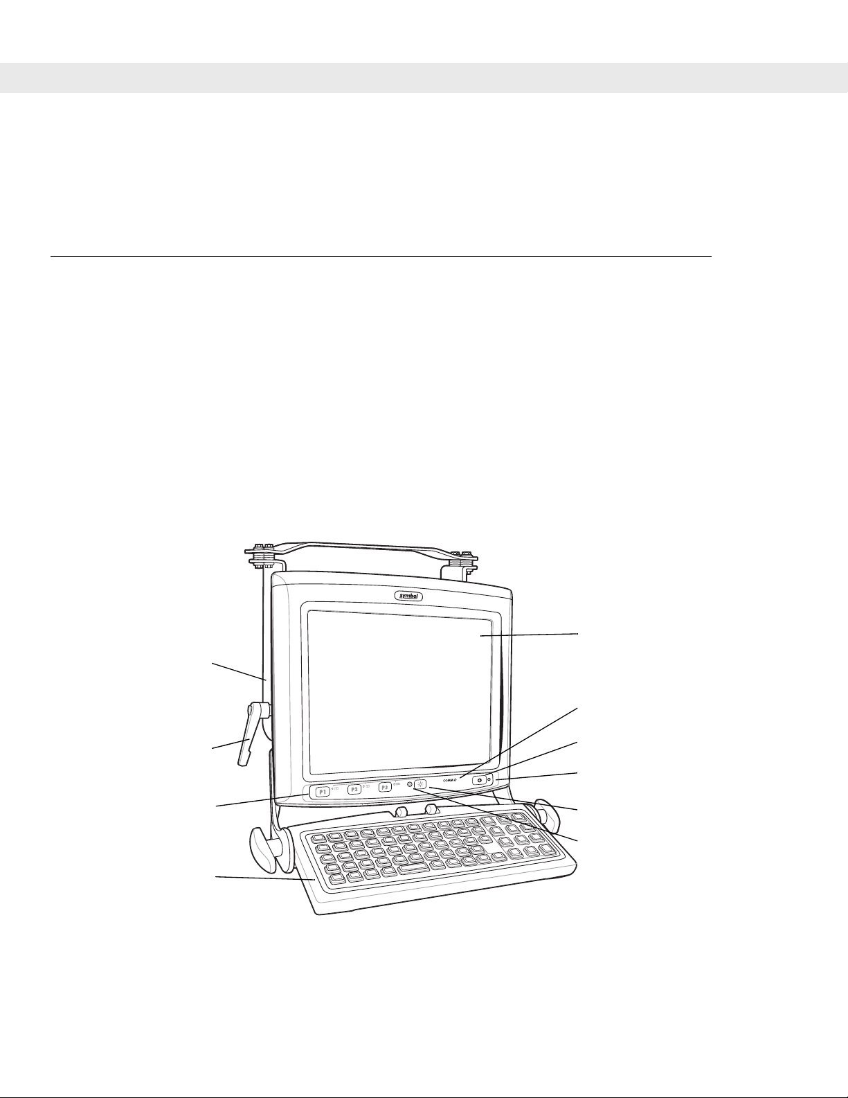
Mounting Bracket
Angle Adjustment
Handle
Quick Access Panel
Keyboard (optional)
Display
COMM LED
Power Button
Power LED
Backlight Control Button
Backlight Control LED
Figure 1-1
VC5090 (Full Screen) Front View
Page 19
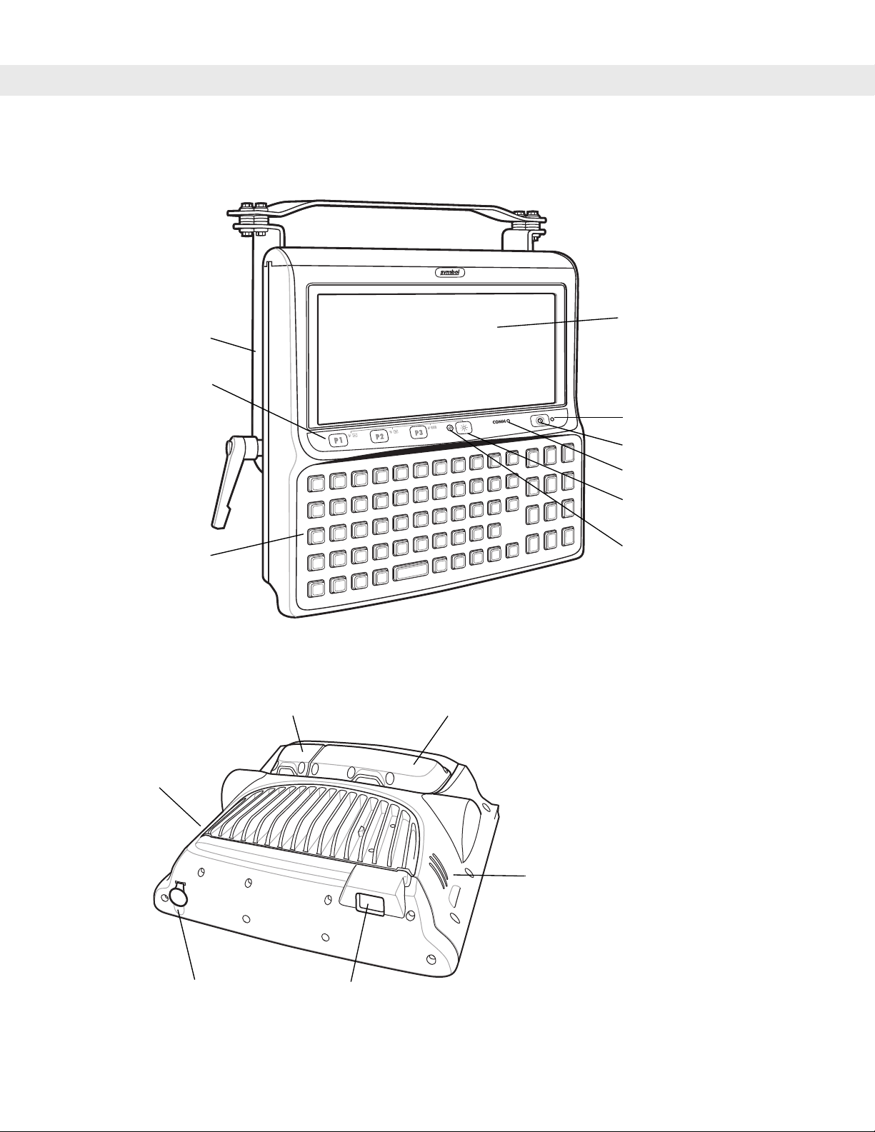
Getting Started 1 - 3
Mounting
Bracket
Quick Access
Panel
Keyboard
Figure 1-2
VC5090 (Half Screen) Front View
Desiccant Door
Display
Power LED
Power Button
COMM LED
Backlight Control Button
Backlight Control LED
UPS/Storage
Card Door
Speaker
Antenna Port for
Optional External
Antenna
Figure 1-3
Speaker
Main Power
Switch
VC5090 Back View
Page 20
1 - 4 VC5090 Vehicle Computer Product Reference Guide
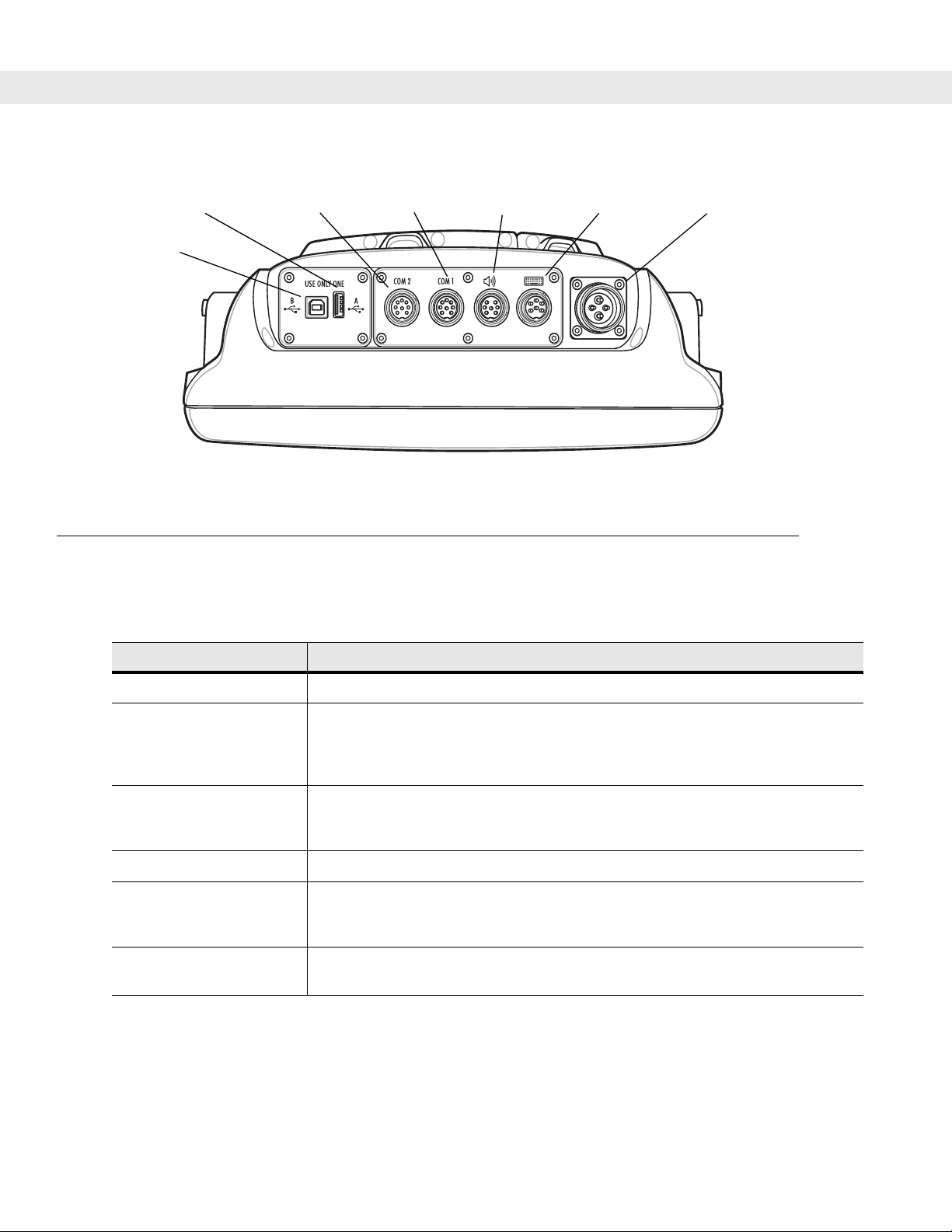
Connector (Host)
USB B
Connector
(Client)
Figure 1-4
Accessories
Table 1-2 lists the accessories available from Symbol for the VC5090:
Table 1-1
USB A
COM2 Port
Connector
VC5090 Bottom View
VC5090 Accessories
COM1 Port
Connector
Audio
Connector
USB/Keyboard
Connector
Power
Connector
Accessory Description
External Keyboard Optional USB keyboard for full-screen configuration.
Screen Protector Replacement screen protector film for either the full screen or half screen
configurations.
Screen Protector for full screen (pkg 5); Part number: S01-69211106-R.
Screen Protector for half screen (pkg 5); Part number: S01-69211107-R.
Uninterruptable Power
Supply Kit
Battery used to maintain operation, for at least 15 minutes, when power is
temporarily interrupted (for example: vehicle battery changes and poor power
conditions). Part Number: BTRY-VC50IAB00.
Desiccant Kit Replacement desiccant bags. Part Number: KT-84524-01.
In-Motion Detector Cable Cable that connects the VC5090 and the vehicle accelerator pedal that detects
when the vehicle is moving and blanks the screen so that the operator is not
distracted while driving. Part number: 25-82420-01R.
Vehicle Power Cable Replacement power cable for connecting the VC5090 to a vehicle power source.
Part number: 25-71919-01R.
Page 21

Getting Started 1 - 5
Table 1-1
VC5090 Accessories (Continued)
Accessory Description
Secure Digital Card Provides secondary non-volatile storage. Recommended secure digital (SD)
cards:
•
128 MB
• ATP part number AF128SDI-AG
• SimpleTech part number SYMNYSD128AE
•
256 MB
• ATP part number AF256SDI-AG
• SimpleTech part number SYMNYSD256AE
•
512 MB
• ATP part number AF512SDI-AG
• SimpleTech part number SYMNYSD512AE
•
1 GB
• ATP part number AF1GBSDI-AG
• SimpleTech part number SYMNYSD1GBAE
Wall Mounting Bracket Use to mount the VC5090 on a wall.
Scanners LS3203 serial laser scanner
LS3408 serial/USB laser scanner
DS3408 serial/USB imager
LS3478 Bluetooth serial/USB laser scanner (with cradle)
DS3478 Bluetooth serial/USB imager (with cradle).
Serial ActiveSync Cable Cable to connect the VC5090 to a host computer to perform serial ActiveSync
communication. Rugged connector to 9-pin RS-232 connector. Part number
25-71914-01R.
USB ActiveSync Cable Cable to connect the VC5090 to a host computer to perform USB ActiveSync
communication. Standard USB B connector to USB A connector. Part number
25-64396-01R.
USB Host Cable Cable to connect the VC5090 as a host device. Rugged connector to USB A jack
connector. Part number 25-71915-01R.
LS3203 Scanner Serial
Cable
LS3408 Scanner Serial
Cable
Cable to connect the Symbol LS3203 serial scanner to the VC5090 serial port.
Part number 25-71916-01R.
Cable to connect the following Symbol serial scanners to the VC5090 serial port.
Part number 25-71917-01R.
•
LS3408 laser scanner
•
DS3408 imager
•
LS3478 Bluetooth laser scanner (with cradle)
•
DS3478 Bluetooth imager (with cradle).
Page 22

1 - 6 VC5090 Vehicle Computer Product Reference Guide
Table 1-1
LS3408 Scanner USB
Cable
RS232 Cable Cable to connect the VC5090 to a serial device. Part number 25-71924-01R.
AC Power Supply Power supply for use in wall or desktop mounted applications. Part number
DC Power Cable Power cable for use in wall or desktop mounted applications that connects the
Software Symbol Mobility Developer Kits, available at: http://devzone.symbol.com.
Peripherals
Table 1-2 lists the peripherals available for the VC5090:
VC5090 Accessories (Continued)
Accessory Description
Cable to connect the following Symbol laser scanners or imagers to the VC5090
USB/Keyboard port. Part number 25-71918-01R.
•
LS3408 laser scanner
•
DS3408 imager
•
LS3478 Bluetooth laser scanner (with cradle)
•
DS3478 Bluetooth imager (with cradle).
50-14001-004 or 50-14001-004R.
AC power supply to the VC5090. Part number 25-71920-01 or 25-71920-01R.
Device Configuration Package for VC5090c (DCP for VC5090c), available at:
http://devzone.symbol.com.
Table 1-2
VC5090 Peripherals
Accessory Description
Headset Provides headset communication for voice over IP (VoIP)
applications.
CB Mode Handset with Adapter
Provides handset communication for audio applications.
Cable
External Antenna Provides external antenna for remote mounting.
Zebra Road Warrior Printer Cable Provides connection between vehicle computer and printer.
Zebra QL-220/320/420 Printer Cable Provides connection between vehicle computer and printer.
O’Neill MF-2T/4T Printer Cable Provides connection between vehicle computer and printer.
Mobility USB Peripheral Ethernet
Dongle
Provides wired Ethernet network connection for fixed mount
applications.
Page 23

Getting Started
In order to start using the vehicle computer for the first time:
•
install the desiccant bags and desiccant door
or
install only desiccant door
•
install the vehicle computer in a vehicle or on a wall or desktop
•
start the vehicle computer.
Installing the Desiccant Bag
NOTE Symbol recommends installing the desiccant bags in environments where extreme temperature changes
occur, such as applications where the device may be continuously moved between a freezer and a hot /
humid area. Desiccant bags should be replaced more often in the hot / humid months of summer and less
frequently in dry/cold months of winter. If desiccant is not used, the desiccant door must still be installed and
secured. Replacement Desiccant Kits are available from Symbol, Part Number: KT-84524-01.
Getting Started 1 - 7
1. Open the desiccant kit and remove all items:
•
desiccant package
•
desiccant door
•
screws.
2. Open the desiccant package and remove the six desiccant bags.
3. Place three desiccant bags in the desiccant well.
4. Place the other three desiccant bags in the back of the desiccant door.
Desiccant Door
Desiccant Bags
Desiccant Well
Figure 1-5
Installing Desiccant Bags
5. Ensure that the door seal is in place.
6. Carefully place the desiccant door onto the back housing. Ensure that the desiccant bags do not interfere
with door seal.
7. Secure the door to the back housing using the four screws.
Page 24

1 - 8 VC5090 Vehicle Computer Product Reference Guide
CAUTION Ensure that you torque the screws to seal the device properly. Otherwise, sealing can be
compromised.
8. Torque the screws to 9 ± 0.5 kgf/cm (7.8 ± 0.4 in-lbs).
Installing the Vehicle Computer
Refer to Chapter 2, Installation for information on installing the vehicle computer onto a vehicle or to a fixed
mount, as well as installing accessories.
Charging the Memory Backup Battery
The vehicle computer is equipped with a memory backup battery which automatically charges from the input
power whether its operating or is in suspend mode. The memory backup battery retains data in memory for at
least 72 hours when power is removed or the UPS is fully discharged. When the vehicle computer is used for
the first time, the backup battery requires approximately 15 hours to fully charge. Do not remove power from
the vehicle computer for 15 hours to ensure that the backup battery fully charges. The Main Power switch on
top of the vehicle computer must be set to the on position. If power is removed from the vehicle computer and
the UPS is fully discharged, the backup battery completely discharges in several hours. The backup battery
retains data in memory for at least 72 hours when power is removed.
NOTE Do not remove power to the vehicle computer within the first 15 hours of use. If the power is removed
before the backup battery is fully charged, data may be lost. The Main Power switch on top of the vehicle
computer must be set to the on position.
Starting the Vehicle Computer
To power on the VC5090, place the Main Power switch, located on the top of the VC5090, to the on (|) position.
The VC5090 initializes and the Symbol splash screen appears followed by the calibration screen. Follow the
instructions for calibrating the screen. If the vehicle computer does not power on, See T roubleshoo ting on page
8-2.
To suspend the VC5090’s operation, press the Power button on the Quick Access Panel. All data is preserved,
so the applications running continue after suspension. Press the Power button again to resume normal
operation.
NOTE The power is applied at all times if the VC5090 is hard wired to the vehicle battery. If using the Ignition
Sense cable and the vehicle ignition is off, then power is not applied to the vehicle computer.
Page 25

Chapter 2
Installation
Introduction
This chapter describes how to install the vehicle computer in a vehicle, on a wall or on a desktop and
connecting the vehicle computer to a power source. There are different installation options depending on the
type of vehicle. This chapter also describes how to install the various accessories for the vehicle computer.
Read all of the following instructions before you begin.
Chapter 2
WARNING! The vehicle computer and bracket must be firmly secured to a surface that can support the
vehicle computer’s weight.
CAUTION A competent engineer must perform the installation in a vehicle. Improper installation can damage
your vehicle and/or the VC5090.
Installation
Do not install the vehicle computer in a location that will affect vehicle safety, driveability, or visibility.
Page 26
2 - 2 VC5090 Vehicle Computer Product Reference Guide
Installing Mounting Brackets
CAUTION It is required to use the Symbol provided mounting bracket.
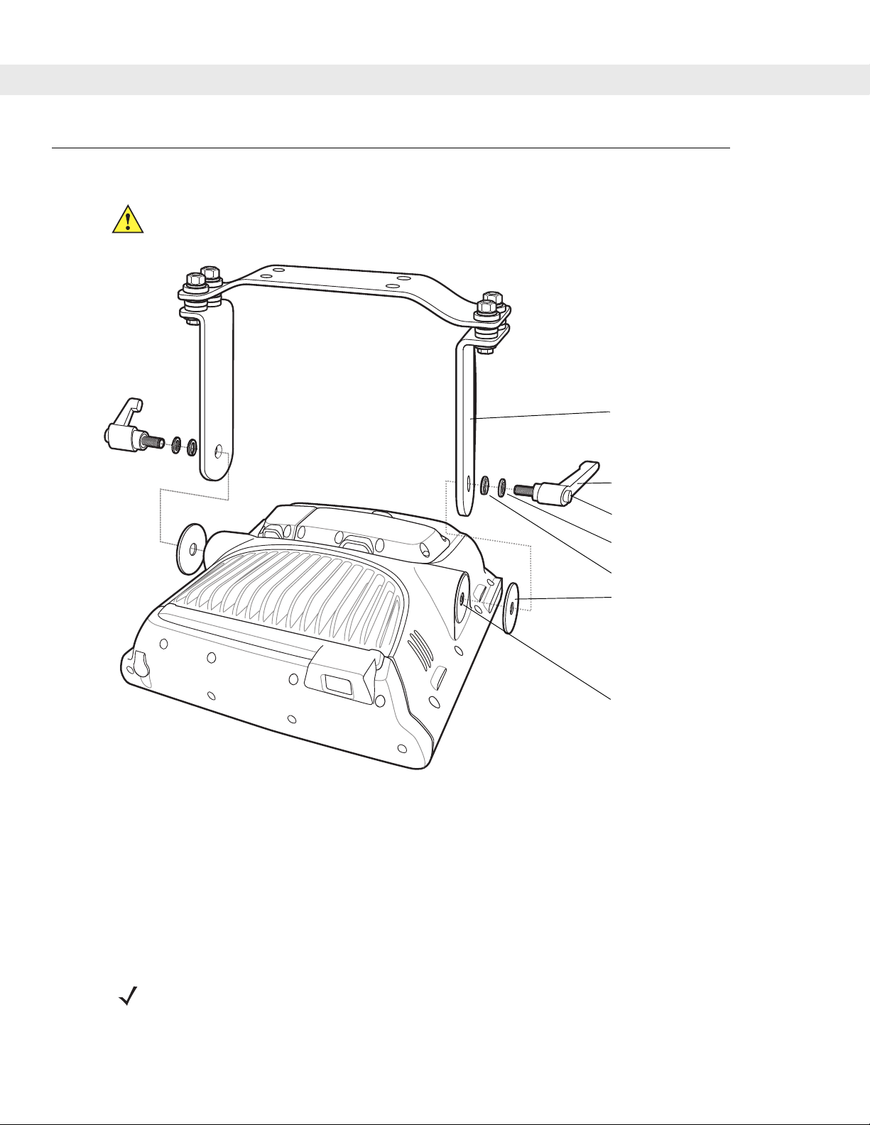
Mounting Bracket
Angle Adjustment
Handle
Figure 2-1
1. Position the friction pads in the friction pad mounting area.
2. Position the mounting bracket over the mounting holes.
3. Place washers onto handle screw.
4. Screw handles into mounting holes and tighten.
Mounting Bracket Installation
Handle Release Button
Flat Washer
Lock Washer
Friction Pad
Friction Pad Mounting
Area
5. The handles can be rotated after they are tightened. Press the handle release button and rotate the
handles to a position where they out of the way.
NOTE If it is not required to re-position the vehicle computer, stainless steel ¾ hardened or full hardened cap
screws (5/16” - 18 - 3/4”) can be used instead of the angle adjustment handles. Torque the cap screws to
276 ± 8.7 kgf/cm (239.6 ± 7.6 in-lbs).
Page 27
Installing the VC5090 in a Forklift
CAUTION A competent engineer must perform the installation in a vehicle. Improper installation can injure the
operator and damage your vehicle and/or the VC5090.
Follow the instructions below to properly install the VC5090 in a forklift.
•
Determine the best location for mounting the vehicle computer taking into consideration the driver’s field
of view and ease of accessing the vehicle computer.
•
Install the appropriate mounting hardware.The VC5090 ships with four cap screws (3/8” - 16 - 2”) for
securing the mounting bracket. If the supplied cap screws are not long enough, use 3/8” - 16 - X cap
screws where X represents the length in inches of the required cap screws.
•
Connect the vehicle computer to the vehicle’s wiring system.
Positioning the Vehicle Computer
•
Determine the best position for the vehicle computer and all the associated components. If a similar
vehicle computer was previously installed, check to see if the position it used is suitable for the VC5090.
Installation 2 - 3
•
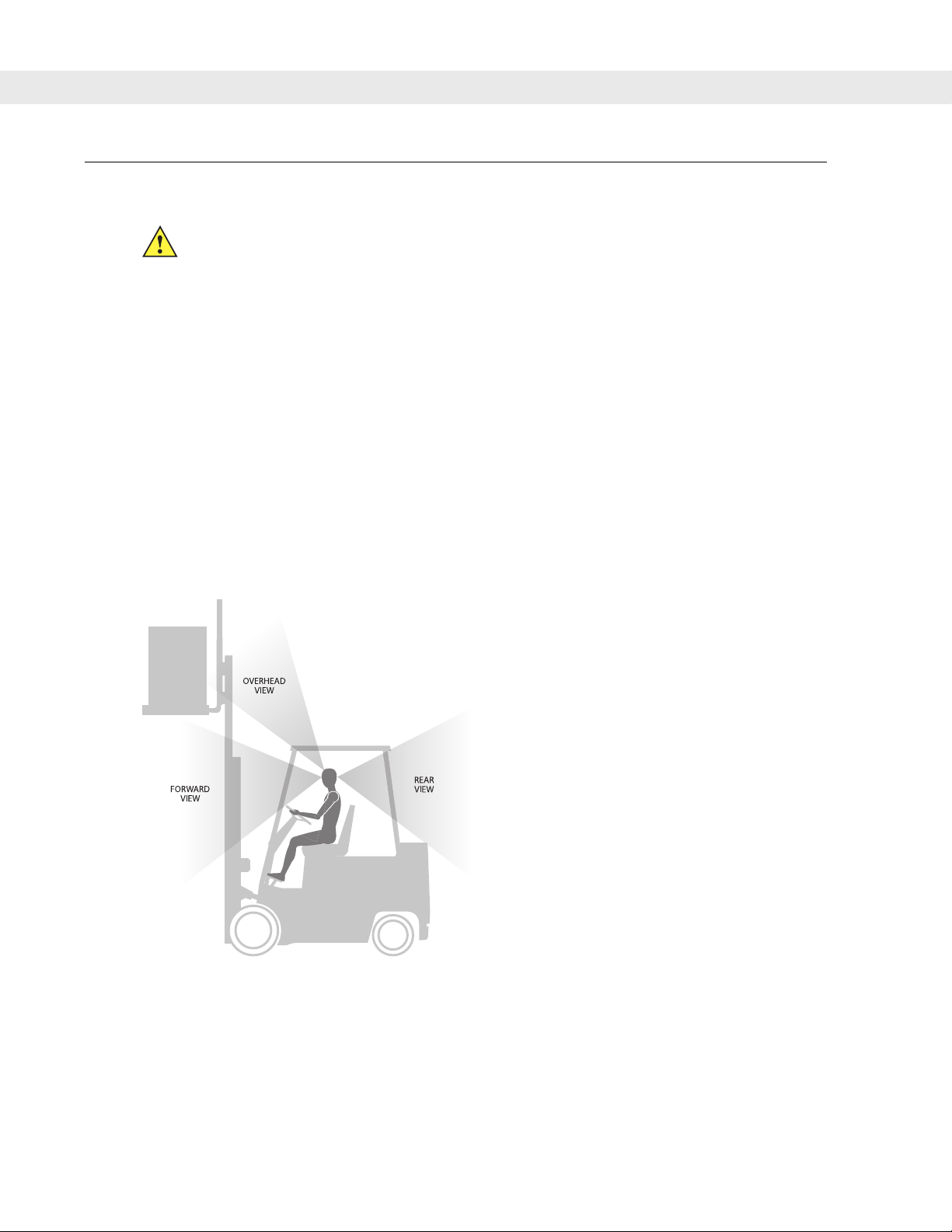
Test the installation for at least 30 minutes before installing on another vehicle. Record all details:
• Check that the position of the vehicle computer does not obstruct vehicle controls.
Figure 2-2
View Obstruction
• Check that the vehicle computer does not obstruct the driver's view.
• Check the position of the vehicle computer for user comfort over long periods.
• Check positioning to avoid extreme wrist angles that may cause injury.
Page 28
2 - 4 VC5090 Vehicle Computer Product Reference Guide
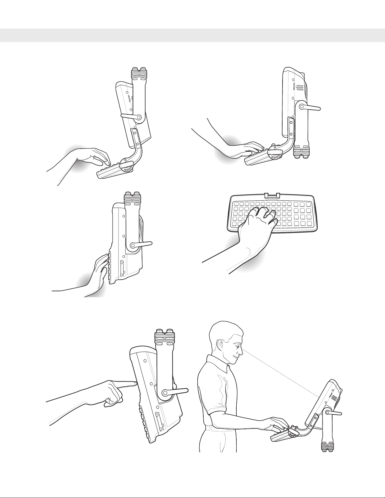
Figure 2-3
Figure 2-4
Avoid Extreme Wrist Angles
Optimum Wrist Positions
Page 29

Mounting the Vehicle Computer
Mounting Bracket Template
Installation 2 - 5
Drill Holes: 10.1 mm ± 0.1 mm
0.43 ± 0.004 in.
160.00 ± 0.20 mm
6.299 ± 0.008 in.
Figure 2-5
25.40 ± 0.10 mm
1.00 ±0.004 in.
Mounting Template
Page 30
2 - 6 VC5090 Vehicle Computer Product Reference Guide
Important Fixing Information
CAUTION Any modification to supplied mounting bracket could cause failure of the unit and/or mountings.
•
A minimum of four fixing positions must be used.
•
All nuts and caps screws must be checked periodically and tightened if required.
•
When installing the vehicle computer, care must be taken to ensure that the mounting bracket footprint is
fully supported. Additional plates may be required to achieve this.
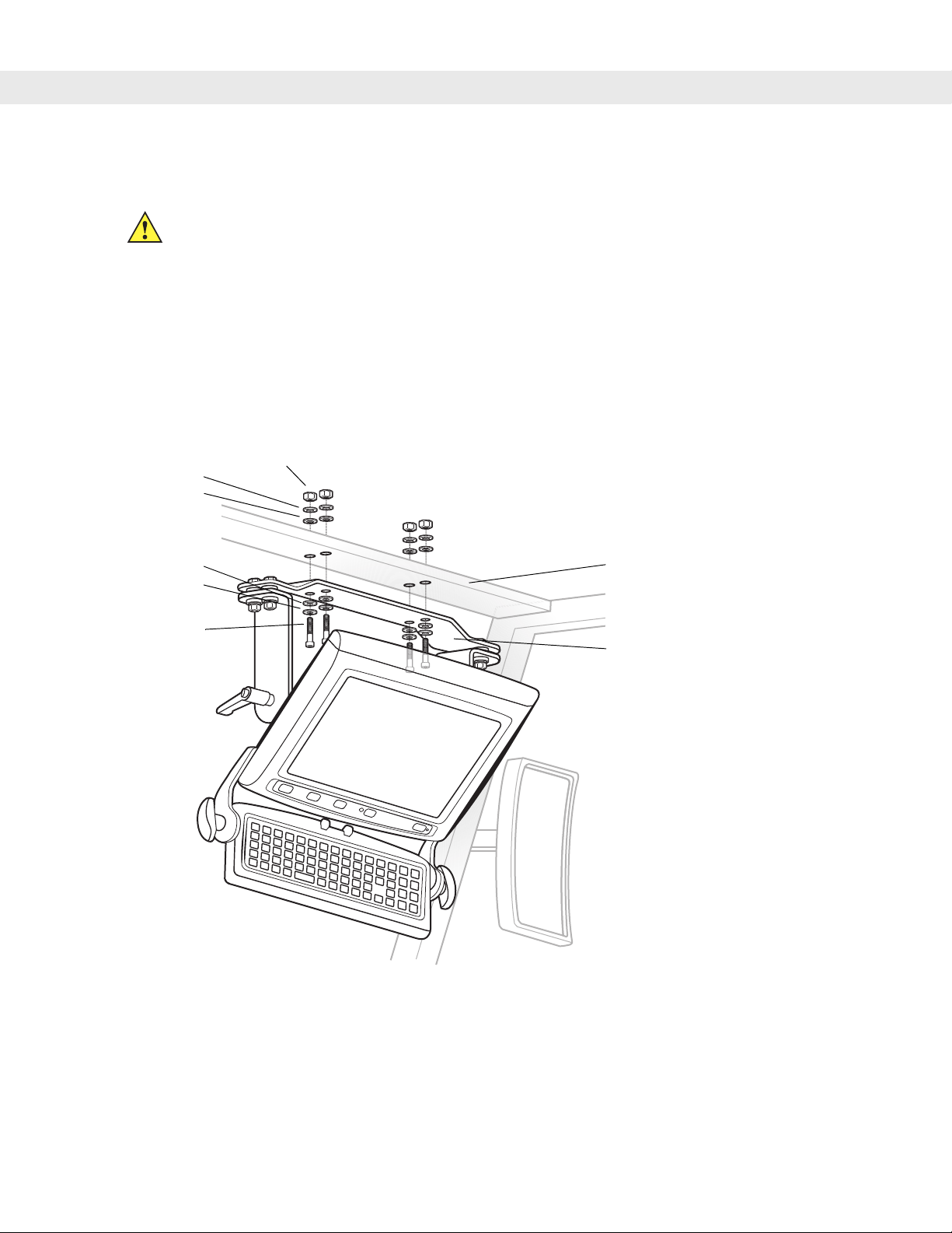
Mounting onto an Over-Head Cross-Beam Example
The diagram below illustrates a typical installation where the vehicle computer is mounted onto a cross-beam.
Nuts
Lock Washers
Flat Washers
Flat Washers
Lock Washers
Cap Screws
Figure 2-6
Vehicle Cross-Beam
Mounting Bracket
Mounting the VC5090 onto an Over-Head Cross-Beam Exampl e
Page 31

Installation 2 - 7
Mounting onto an Over-Head Cage Example
The diagram below illustrates a typical installation where the vehicle computer is mounted on a cage.
Customer Supplied
Lock Washers
Flat Washers
Flat Washers
Lock Washers
Cap Screws
Nuts
Mounting Bracket
Mounting Bracket
Figure 2-7
Mounting the VC5090 onto an Over-Head Cage Example
Page 32

2 - 8 VC5090 Vehicle Computer Product Reference Guide
Mounting on a Dashboard or Horizontal Surface Example
The diagram below illustrates a typical installation where the vehicle computer is mounted on a dashboard or
horizontal flat surface.
NOTE If mounting to a thin surface, a reinforcing plate maybe required.
Cap Screws
Flat Washers
Lock Washers
Mounting Bracket
Mounting Surface
Flat Washers
Lock Washers
Nuts
Figure 2-8
Mounting on a Vehicle Shelf
Routing Electrical Cables
•
Establish a neat route for the cable, staying clear of moving parts or hot surfaces.
•
Fix the cable to existing cable runs inside the vehicle using cable ties, but make sure they are away from
any moving or hot surfaces.
•
When the cabling must go through a panel, use a suitable gland.
•
When fixing the conduit or cable on the outside of a vehicle, use P-Clips. Either drill and tap the hole or
use a nut and bolt to secure the clip.
•
Ensure the cable does not have tight bends. The minimum recommended radius is 63.5 mm (2.5 in.).
•
On electric vehicles, take the power from as close to the battery as possible, but not directly from the
battery terminals, and not before any main fuse.
•
On gasoline, diesel or propane vehicles, take the power from as close to the battery terminals as
possible, and avoid using existing wiring.
•
All fuses must be as close as possible to the power source.
•
If you are unsure of the correct power source, contact the vehicle manufacturer for more information.
Page 33

Installation 2 - 9
12-24 Volt Gasoline, Diesel, or Propane Forklifts
NOTE The vehicle computer contains an Ignition Sense feature that detects when the ignition switch is turned
off and shuts the vehicle computer down after a preprogrammed timeout. This feature allows the operator
to use the vehicle computer for a predetermined time period after the ignition switch is turned off, then
shuts the vehicle computer down automatically to prevent over-discharge of the forklift battery. The
timeout period is adjustable by the user (see Ignition Sensing on page 3-17 for setting the timeout value).
The normal current draw of a suspended vehicle computer is approximately 500mA. When the vehicle
computer shuts down using the Ignition Sense feature, current draw is reduced to approximately 5 mA.
This feature provides the automatic shutoff functionality of an external relay, without requiring an actual
relay and has the added benefit of allowing the user to work for a preset time period before shutting
down.
•
All power wiring must use the supplied power cable.
•
Fuses:
• two 3AG, 20A, 250V, SLO BLO fuses
• one 3AG, 1A, 250V, SLO BLO fuse.
•
Keep the path between the battery and the vehicle computer as short as possible, and away from any
part of the ignition high tension system.
Vehicle
Battery
Figure 2-9
1A Fuse
Ignition
Switch
20A Fuse
20A Fuse
Chassis Ground
Wiring Diagram
Yell ow
Red
Black
Green
Electric Forklifts Up to 60 Volts
•
All power wiring must use the supplied power cable.
•
Fuses:
• two 3AG, 20A, 250V, SLO BLO fuses
• one 3AG, 1A, 250V, SLO BLO fuse.
Power Cable
25-71919-01
VC5090
Page 34

2 - 10 VC5090 Vehicle Computer Product Reference Guide
1 A Fuse
or
Yellow
Vehicle
Battery
Figure 2-10
Switch
20A Fuse
20A Fuse
Chassis Ground
Wiring Diagram
Red
Black
Green
Power Cable
25-71919-01
VC5090
Connecting the Power Cable
NOTE See the vehicle Owner's Manual for specific wiring information.
1. Disconnect the vehicle battery.
2. Connect the green wire to the vehicle’s chassis.
3. Shorten cable to desired length.
4. Place a fuse and fuse holder in-line of the red, black and yellow wires approximately four inches from the
cable end, as shown below.
Wire
Fuse Holder Fuse HolderShrink Tubing Fuse
Figure 2-11
5. Slide shrink tubing over wires.
6. Strip wires (0.4 in./10 mm) and insert into the fuse holder. Crimp fuse holder ends to ensure a proper
Fuse Connection
Wire
Shrink Tubing
electrical connection (use Thomas & Betts WT-11-M crimp tool or equivalent).
7. Heat shrink tubing.
8. Connect the red wire to the vehicle's positive power source. Connect the black wire to the vehicle's
negative power source.
Page 35

Installation 2 - 11
NOTE The vehicle computer contains an Ignition Sense feature that detects when the ignition switch is turned
off and shuts the vehicle computer down after a preprogrammed timeout. This feature allows the operator
to use the vehicle computer for a predetermined time period after the ignition switch is turned off, then
shuts the vehicle computer down automatically to prevent over-discharge of the forklift battery. The
timeout period is adjustable by the user (see Ignition Sensing on page 3-17 for setting the timeout value).
The normal current draw of a suspended vehicle computer is approximately 500mA. When the vehicle
computer shuts down using the Ignition Sense feature, current draw is reduced to approximately 5 mA.
This feature provides the automatic shutoff functionality of an external relay, without requiring an actual
relay and has the added benefit of allowing the user to work for a preset time period before shutting
down.
9. Connect the yellow wire to the vehicle's ignition switch. If you do not plan on using the Ignition Sense
feature, connect the yellow wire to the vehicle’s positive power source.
10. Ensure the wiring connections created are sufficiently insulated from each other.
11. Re-connect the vehicle battery.
12. Insert the power cable connector into the vehicle computer's Power port. Align the keyway on the power
connector with the notch on the vehicle computer’s power port.
Removing Power to the Vehicle Computer
NOTE Place the vehicle computer in suspend mode prior to removing power.
If it is required to remove the vehicle computer from a power source (replace a vehicle’s battery):
1. Ensure that all the Forklift Ignition Off wakeup settings are set to No. Tap > Settings > Control Panel >
Power icon > Wakeup tab to view the wakeup settings.
2. Press the Power button on the Quick Access Panel to place the vehicle computer in suspend mode.
3. Turn the vehicle ignition switch to the off position, if applicable.
4. Remove power to the vehicle computer.
5. After re-applying power, turn the vehicle ignition switch to the on position, if applicable.
6. Press the Power button on the Quick Access Panel to resume normal operation.
Page 36

2 - 12 VC5090 Vehicle Computer Product Reference Guide
Installing the VC5090 on a Wall or Desktop
To use the vehicle computer in a wall mounted application:
•
Install the mounting bracket to the wall.
•
Connect the vehicle computer to the AC power supply.
Mounting the Bracket on a Wall
NOTE If mounting to a thin surface, a reinforcing plate maybe required.
Flat Washers
Lock Washers
Cap Screws
Nuts
Lock Washers
Flat Washers
Optional Wall
Mounting Bracket
Figure 2-12
Mounting on a Wall
Page 37

Mounting the Bracket on a Desktop
NOTE If mounting to a thin surface, a reinforcing plate maybe required.
Cap Screws
Flat Washers
Lock Washers
Flat Washers
Lock Washers
Nuts
Installation 2 - 13
Mounting Bracket
Mounting Surface
Figure 2-13
Mounting on a Desktop
Page 38

2 - 14 VC5090 Vehicle Computer Product Reference Guide
Connecting the Vehicle Computer to AC Power
NOTE Use only a Symbol-approved power supply, output rated 12 VDC and minimum 9A (part number
50-14001-004 or 50-14001-004R). The power supply is certified to EN60950 with SELV outputs.
HINWEIS Benutzen Sie nur eine Symbol Technologies genehmigt Stromversorgung in den Ausgabe: 12 VDC und
minimum 9A (part number 50-14001-004 or 50-14001-004R). Die Stromversorgung ist bescheinigt
nach EN60950 mit SELV Ausgaben.
To provide power from an AC source:
1. Insert the AC line cord into the AC connector on the universal power supply.
Universal Power Supply
(50-14001-004
or 50-14001-004R)
AC Line Cord
Power Port
DC Power Cable
(25-71920-01 or
25-71920-01R)
Figure 2-14
2. Plug the other end of the AC power cable into a wall outlet.
3. Insert the DC power cable into the DC connector on the universal power supply.
4. Plug the other end of the cable into the vehicle computer’s Power port.
Connecting AC power
Page 39

Installing the Optional Keyboard
NOTE The optional keyboard is only available on the full-screen configuration.
The keyboard kit contains the following items:
•
keyboard
•
two keyboard brackets
•
four cap screws with captive washers
•
two locking knobs
•
four flat and lock washers.
1. Attach the keyboard brackets to both sides of the VC5090, using the cap screws with captive washers.
Left Hand
Bracket
Installation 2 - 15
Cap Screws with
Captive Washers
Figure 2-15
2. Torque the screws to 230 kgf/cm (200 in-lbs).
3. Squeeze the quick release tabs on the keyboard and align the keyboard with the brackets.
Attaching the Brackets to the VC5090
Page 40

2 - 16 VC5090 Vehicle Computer Product Reference Guide
Quick Release Tabs
Figure 2-16
4. Release the quick release tabs to insert the alignment pins through an alignment hole on each of the
Quick Release Tabs
brackets.
5. Insert the keyboard locking knobs through the brackets and screw into the keyboard.
Flat Washer
Lock Washer
Locking Knob Retracted
Alignment Pin
Holes
Screw Hole
Alignment
Pin
Figure 2-17
6. Tighten the locking knobs.
7. Plug the keyboard cable into the USB/Keyboard connector on the back of the VC5090.
Attaching the Keyboard
Page 41

USB/Keyboard Connector
Installation 2 - 17
Keyboard Cable
Figure 2-18
Keyboard Port
Adjusting the Keyboard
To adjust the keyboard:
1. Loosen the locking knobs.
Figure 2-19
Loosen Locking Knobs
2. Squeeze the quick release tabs.
Figure 2-20
Squeeze Quick Release Tabs
Page 42

2 - 18 VC5090 Vehicle Computer Product Reference Guide
3. Move the keyboard to the desired position.
Figure 2-21
4. Release the quick release tabs.
5. Tighten the locking knobs.
Figure 2-22
Adjust Keyboard
NOTE Ensure that the positioning pins lock into the positioning holes in both brackets.
Tighten Locking Knobs
Page 43

Installing a Scanner
The following Symbol scanners can be connected to the vehicle computer:
•
LS3203 serial laser scanner
•
LS3408 serial/USB laser scanner
•
DS3408 serial/USB imager
•
LS3478 Bluetooth laser scanner (with serial/USB cradle)
•
DS3478 Bluetooth imager (with serial/USB cradle).
Connecting a Serial Scanner
NOTE Refer to the scanner Product Reference Guide for information on configuring the scanner.
To connect a serial scanner to the VC5090:
1. Connect the appropriate serial scanner cable to the scanner or the cradle.
Installation 2 - 19
2. Connect the serial scanner cable to the COM1 or COM2 port.
COM2 Port
Figure 2-23
Connecting Serial Scanner to COM1 and COM2 Connectors
COM1 Port
If you are using the SerialWedge follow the setup instructions in Scanner Setup on page 2-20.
Connecting a USB Scanner
To connect a USB scanner to the VC5090:
NOTE Refer to the scanner Product Reference Guide for information on configuring the scanner.
The USB scanner cable connects to the USB/Keyboard connector. If the optional keyboard is used on the
VC5090 Full-screen configuration, you are not allowed to connect a USB scanner on the rugged USB
port. Connecting a USB scanner to the USB A port is not recommended.
Page 44

2 - 20 VC5090 Vehicle Computer Product Reference Guide
1. Connect the appropriate USB scanner cable to the scanner or cradle.
2. Connect the USB scanner cable to the USB/Keyboard connector.
USB/Keyboard Connector
USB Cable
Figure 2-24
Connecting USB Scanner to Keyboard Connector
If you are using SerialWedge application, follow the setup instructions in the following section.
Scanner Setup
To configure the VC5090 to communicate with the scanner:
1. Double-tap the SerialWedge icon on the desktop to launch the application.
2. Tap the SerialWedge icon in the task tray.
3. Select Configuration > Port Selection from the pop-up menu. The Port Selection window appears.
Figure 2-25
Port Selection Window
4. Select the COM port radio button to match the COM port that you connected the scanner cable to.
5. Ta p OK.
The scanner beeps to indicate that it is receiving power.
6. Tap the SerialWedge icon in the task tray.
7. Select Configuration > Port Configuration from the pop-up menu. The Communication Parameters window
appears.
Page 45

Installation 2 - 21
Figure 2-26
8. Use the drop-down lists to select the parameter values to match the scanner. Refer to the scanner Product
Communications Parameters Window
Reference Guide for more information.
9. Ta p OK.
10. Tap the SerialWedge icon in the task tray.
11. Select Configuration > Barcode Settings from the pop-up menu. The Barcode Settings window appears.
Figure 2-27
12. Enter or select configuration parameters as required:
Barcode Settings Window
•
Prefix - Appends the data entered in this field to the beginning of the bar code data.
•
Suffix - Appends the data entered in this field to the end of the bar code data.
•
Allow Escapes in prefix/suffix - Allows the prefix and suffix data to contain escape keys.
•
Send barcode data - when enabled, the barcodes data is sent to the vehicle computer.
•
Send barcode data as ASCII - when enabled, the barcodes data is sent in the ASCII format.
•
Send Enter key after suffix - when enabled, an Enter character is appended to the end of the bar code
data.
•
Send TAB key after suffix - when enabled, an Tab character is appended to the end of the bar code
data.
13. Ta p OK.
Page 46

2 - 22 VC5090 Vehicle Computer Product Reference Guide
Enable/Disable the Scanner
To enable or disable the scanner:
1. Tap the SerialWedge icon in the task tray.
Scan > Enable from the pop-up menu to enable the scanner if it had previously been disabled. The
Select
scanner beeps to indicate that it is receiving power.
or
Select
Scan > Disable from the pop-up menu to disable the scanner if it had previously been enabled.
Displaying Bar Code Data
To display scanner bar code data on the display:
1. Tap the SerialWedge icon in the task tray.
2. Select Show UI. The Show Barcode data window appears.
Figure 2-28
3. Aim the scanner at a bar code and press the scan trigger. The bar code data appears in the window.
Show Barcode Data Window
Pairing Bluetooth Scanner and Cradle
The Bluetooth scanner cradle receives power from the vehicle computer. When the vehicle computer goes into
suspend mode the vehicle computer removes power to the cradle. When the vehicle computer resumes
normal operation, power is re-applied to the cradle. If power to the cradle was removed for more than 30
seconds, the scanner needs to re-connect (pair) to the cradle. Press the scanner trigger to re-connect the
scanner to the cradle. The scanner emits a lo-high beep when re-connecting.
Page 47

Installing the Uninterruptable Power Supply
NOTE The Uninterruptable Power Supply (UPS) Kit comes with eight replacement screws.
To install the UPS:
CAUTION Use ESD precautions when installing the UPS.
1. Place the Main Power switch on top of the vehicle computer to the off position.
2. Remove and discard the eight screws securing the UPS/Storage Card door on the back of the vehicle
computer.
Installation 2 - 23
Figure 2-29
3. Connect the UPS connector to the connector on the printed circuit board (PCB).
4. Place the UPS into the well.
UPS/Storage Card Door Removal
Page 48

2 - 24 VC5090 Vehicle Computer Product Reference Guide
Figure 2-30
5. Place the UPS/Storage Card door over the UPS and secure using the eight new screws.
6. Torque the screws to 9 ± 0.5 kgf/cm (7.8 ± 0.4 in-lbs).
7. Place the Main Power switch to the on position.
Connecting UPS to PCB
CAUTION Ensure that you torque the screws to seal the device properly. Otherwise, sealing can be
compromised.
The UPS fully charges in approximately four hours.
Page 49

Installing a Secure Digital Card
A Secure Digital (SD) card provides secondary non-volatile storage. The card holder is located on the back of
the VC5090.
To install the SD card:
1. Place the Main Power switch on the top of the vehicle computer to the off position.
2. Remove and discard the eight screws securing the UPS/Storage Card door.
Installation 2 - 25
Figure 2-31
3. Lift the SD card retaining door.
Figure 2-32
4. Position the SD card, with the contacts down, into the card holder. The SD card corner notch fits into the
holder only one way.
UPS/Storage Card Door Removal
Retaining Clip
Lift Retaining Door
Page 50

2 - 26 VC5090 Vehicle Computer Product Reference Guide
Figure 2-33
5. Snap the retaining door closed.
Figure 2-34
6. Place the UPS/Storage Card door over the UPS and secure using the eight new screws.
7. Torque the screws to 9 +/- 0.5 kgf/cm (7.8 ± 0.4 in-lbs).
Position of SD Card
Close Retaining Door
CAUTION Ensure that you torque the screws to seal the device properly. Otherwise, sealing can be
compromised.
8. Place the Main Power switch to the on position.
Page 51

Installing a External Antenna
NOTE Symbol recommends using the Centurion™ antenna, model number: WTS2450-RPSMA.
An external antenna can be used when placement of the vehicle computer prohibits reception; i.e., inside a
vehicle cab.
To install an external antenna:
1. Lift the antenna connector cap on top of the vehicle computer.
2. Screw the cable connector onto the antenna connector.
3. Torque to 5 ± 0.5 kgf/cm (4.3 ± 0.4 in-lbs).
Installation 2 - 27
Antenna (Customer
provided)
Antenna Base
(Customer provided)
Antenna Connector Cap
Note: The antenna and antenna base drawing is an
example and actual antennas and bases may vary.
Figure 2-35
4. Screw the antenna to the antenna base.
5. Tap > Settings > Control Panel > VC5090 System Management icon. The System Management window
Antenna Installation Example
NOTE When selecting an external antenna, the primary internal WLAN antenna is disabled.
displays.
Page 52

2 - 28 VC5090 Vehicle Computer Product Reference Guide
Figure 2-36
6. Tap the RF Settings tab.
7. Tap the External Antenna radio button.
8. Ta p OK.
RF Settings Tab Window
Installing the Vehicle In-Motion Detector
The optional Vehicle In-Motion Detector cable blanks the screen and disables use of the vehicle computer
when the vehicle is in motion. The customer must install a switch that is engaged when the vehicle accelerator
pedal is not depressed. When the pedal is not depressed, the switch is activated (closed) and sends a signal to
the vehicle computer indicating that the pedal is not depressed. When the accelerator pedal is depressed the
switch disengages and the signal removed. The screen blanks and the touch screen and keyboard are
disabled.
Whenever the vehicle is in motion (accelerator pedal is depressed) and the Terminal Locking feature is
enabled, the vehicle computer display blanks. When the accelerator pedal is not depressed, the vehicle
computer does not unlock immediately. Instead, the
vehicle computer continues to remain locked. This ensures that the vehicle computer doesn’t unlock and lock
during any momentary disengagement of the accelerator pedal. While the
running, the touch screen, backlight and keyboard are disabled. After this timer expires, the
Timeout
are still disabled. If during this time the user touches the screen, the backlight comes on and the vehicle
computer unlocks fully. Otherwise after this timer expires, the backlight comes on and the vehicle computer
unlocks fully. If, while any of these timers are running, the vehicle pedal is pressed, the vehicle computer locks
again.
timer initiates. While this timer is running, the touch screen is enabled but the backlight and keyboard
Complete Lockup Timeout timer initiates during which the
Complete Lockup Timeout timer is
Screen Blank
If the cable is cut or removed, the vehicle computer responds as if the pedal is depressed.
Switches
There are two types of switches that can be used; a solid state switch and a mechanical switch. Typically solid
state switches have a much longer life cycle than mechanical switches. Solid state switches require power
while mechanical switches do not.
Page 53

Installation 2 - 29
The switch must be rated at 5V, 10 mA and it should have a operating temperature, sealing and life cycle
applicable for the environment that it is used in.
The mechanical switch must be a Normally Open type of switch.
The supply voltage for the solid state switch is 5 VDC (500 mA max.). When the switch is depressed the OUT
pin is pulled low.
The switch must be mounted permanently and must be positioned in such a way so that the switch is
depressed when the accelerator pedal is not pressed (vehicle at rest). When the accelerator pedal is pressed,
the switch should open and stay open until the pedal is released completely.
Vehicle Stationary
Switch (Closed)
Cable
Mounting
Hardware
Accelerator
Pedal
Note: Diagram is for concept only. Actual switch, pedal, mounting hardware and installation vary depending upon the
type of vehicle and hardware used.
Figure 2-37
Switch Installation Example
Accelerator
Pedal
Vehicle In-Motion
Switch (Open)
Cable Installation
One end of the cable connects to a customer provided switch and the other end connects to the COM1 or
COM2 port on the vehicle computer.
To install the Vehicle In-Motion Detector cable:
Cable
Mounting
Hardware
1. Follow these recommendations when installing the cable:
•
Establish a neat route for the cable, staying clear of moving parts or hot surfaces.
•
Place the cable in a rigid sleeve or conduit to protect the cable.
•
When the cabling must go through a panel, use a suitable gland.
•
When fixing the conduit or cable on the outside of a vehicle, use P-Clips. Either drill and tap the hole or
use a nut and bolt to secure the clip.
•
Ensure the cable does not have tight bends. The minimum recommended radius is 2.5".
•
Solder all wire connections.
2. Wire the cable and switch as shown in Figure 2-38.
Page 54

2 - 30 VC5090 Vehicle Computer Product Reference Guide
Figure 2-38
3. Connect the connector of the Vehicle In-Motion Detector cable to either the COM1 or COM2 connector on
In-Motion Detector Cable Wiring
the back of the VC5090.
4. On the vehicle computer, tap > Settings > Control Panel > VC5090 System Management icon. The
System Management window displays.
Figure 2-39
5. Tap the Terminal Lock tab. The Terminal Lock Password window appears.
System Management - Terminal Lock
Figure 2-40
6. Enter the assigned password and tap OK. The default password is “vc5090”.
System Management - Terminal Lock
Page 55

7. Select the Enable Terminal Locking check box.
Installation 2 - 31
Figure 2-41
8. In the Select control for terminal locking drop-down list, select the COM port that the In-Motion Detector
Terminal Lock Tab
cable is connected to (either COM1 or COM2).
9. In the Complete Lockup Timeout drop-down list, select the amount of time that the VC5090 waits before it
unlocks once the switch is deactivated (pedal is disengaged). During this time period, the touch screen,
backlight and keyboard are disabled.
10. In the Screen Blank Timeout drop-down list, select the amount of time after the Complete Lockup TImeout
that the touch screen is active. The touch screen is enabled but the backlight and keyboard are disabled.
11. Ta p OK.
To change the Terminal Lock password:
1. On the vehicle computer, tap > Settings > Control Panel > VC5090 System Management icon. The
System Management window displays.
2. Tap the Terminal Lock tab. The Terminal Lock Password window appears.
Figure 2-42
3. Enter the assigned password and tap OK. The password is case sensitive.The default password is
System Management - Terminal Lock
“vc5090”.
4. Ta p Set New PASSWORD. The Set New Password window appears.
Page 56

2 - 32 VC5090 Vehicle Computer Product Reference Guide
Figure 2-43
5. In the Old Password text box, enter the old password.
6. In the New Password text box, enter the new password. The password must have a minimum of five
Set New Password Window
characters.
7. In the Confirm Password, re-enter the new password.
8. Ta p OK.
Over-Ride
If the cable is cut or breaks, you can over-ride the lock out by tapping the screen three times. A dialog box
appears. In the
Unlock Password field, enter the password and tap OK.
Figure 2-44
Terminal Lock Over-Ride
Page 57

Connecting Accessories
Connect an optional scanner, ActiveSync serial cable, or USB device (such as a keyboard or mouse) using the
appropriate port on the bottom of the VC5090.
You should use either COM1 or COM2 port for serial ActiveSync or the USB Client port for USB ActiveSync.
A standard USB keyboard or mouse can be connected to the USB A connector (Host).
Installation 2 - 33
Connector (Host)
USB B
Connector
(Client)
Figure 2-45
USB A
Connection Ports
COM2 Port
Connector
COM1 Port
Connector
Audio
Connector
USB/Keyboard
Connector
Connecting an External Speaker to the Vehicle Computer
It may be necessary to install an external speaker in noisy environments. To connect an external speaker, a
special cable must be created to connect the vehicle computer to the external speaker. Figure 2-46 illustrates
the cable requirements. See Audio Connector Pin-Outs on page A-5 for the connector pin-outs and required
connector.
.
Power
Connector
Figure 2-46
External Speaker Wiring Diagram
The speaker must be a minimum of 4 ohms (4 or 8 ohms is preferred). The speaker must be rated for 2.5W
continuous at 4 ohms or 1.5W continuous at 8 ohms.
Page 58

2 - 34 VC5090 Vehicle Computer Product Reference Guide
Page 59

Chapter 3
Chapter 3
Operating the VC5090
Introduction
This chapter explains the buttons, status icons and controls on the VC5090 and provides basic instructions for
using the VC5090, including powering on and resetting. It also included instructions for entering and capturing
data.
Quick Access Panel
The Quick Access Panel contains buttons and LEDs to control the operation of the vehicle computer.
Operating the VC5090
P1 Button
Figure 3-1
P2 Button
VC5090 Quick Access Panel
P3 Button
Backlight Control LED
COMM LED
Power Button
Power LEDBacklight Control Button
Power Button
Press the Power button to place the vehicle computer into suspend mode. When in suspend mode, press the
Power button to resume normal operation.
Power LED
Table 3-1 lists the states of the Power LED.
Table 3-1
Solid Green Vehicle computer is operating from external power.
Power LED Indicator
LED State Indication
Page 60

3 - 2 VC5090 Vehicle Computer Product Reference Guide
Table 3-1
Power LED Indicator
LED State Indication
Flashing Green UPS battery is charging.
Solid Yellow Vehicle computer is operating from the UPS battery.
Flashing Yellow Vehicle computer is operating from the UPS battery and the UPS battery power is low.
COMM LED
The COMM LED blinks to indicate WLAN radio activity. Table 3-2 lists the states of the COMM LED. By default,
the COMM LED is enabled. To disable the COMM LED:
NOTE These settings are not persistent across a cold boot.
1. Tap > Settings > Control Panel > VC5090 System Management icon. The System Management window
displays.
Figure 3-2
2. Tap the Enable Comm Led check box.
3. Ta p OK.
Table 3-2
RF Settings Tab Window
COMM LED Indicator
LED State Indication
Fast Blinking (once every 0.4 seconds) Excellent WLAN signal.
Medium Blinking (once every 0.8 seconds) Very Good WLAN signal.
Slow Blinking (once every 1.6 seconds) Good WLAN signal.
Off
Poor WLAN signal. Radio is not associates with an AP.
Radio is disabled. COMM LED is disabled.
Page 61

Operating the VC5090 3 - 3
Backlight Control Button
The Backlight Control button places the Quick Access Panel’s P1, P2 and P3 buttons into the backlight control
mode where you can adjust the brightness of the display or turn on/off the keyboard backlight. See Adjusting
the Brightness on page 3-8 for more information.
Programmable (“P”) Keys
The programmable keys on the Quick Access Panel (P1, P2, P3) can be set to perform certain functions, such
as:
•
launching an application
•
simulating a key press
•
toggling the SIP keyboard
•
enabling and disabling the touch screen
•
toggling the keyboard backlight
•
playing a key sequence
•
launching the calibration screen.
NOTE These settings are not persistent across a cold boot.
To set a programmable key:
1. Ta p > Settings > Control Panel > Programmable Keys icon. The Configure Programmable Keys window
appears.
Figure 3-3
2. In the Key: drop-down menu, select the P key you would like to program.
3. In the Action drop-down menu. select the function you would like the P key to perform.
Programmable Keys Screen, Key Drop-Down Menu
4. In the action fields, enter the required data, if applicable. See the following paragraph for more information.
5. Ta p OK.
Page 62

3 - 4 VC5090 Vehicle Computer Product Reference Guide
Launch Application
To set a programmable key to launch an application:
1. In the Action drop-down list, select Launch Application.
Figure 3-4
2. In the Application Path field enter the path and application or tap the button to browse through the folders to
Configure Programmable Keys - Launch Application
find the application file.
3. In the Command Line field, enter any specific commands for the selected application.
4. Ta p OK.
Simulate KeyPress
To set a programmable key to simulate a key press:
1. In the Action drop-down list, select Simulate KeyPress.
Figure 3-5
2. In the Modifiers field, select one of the check boxes.
3. In the Key Press drop-down list, select a key (character).
4. Select the Repeat Key check box to allow the key press to continuously repeat as long as the P button is
Configure Programmable Keys - Simulate KeyPress
pressed.
5. Ta p OK.
Page 63

Play Key Sequence
To set a programmable key to play a sequence of characters:
1. In the Action drop-down list, select Play Key Sequence.
Operating the VC5090 3 - 5
Figure 3-6
2. In the Key Sequence field, enter a character string (up to 1,040 characters).
3. Ta p OK.
Configure Programmable Keys - Play Key Sequence
Using the Keyboard
An optional QWERTY keyboard can be used with the full-screen vehicle computer. Refer to Figure 3-7 and
Table 3-3 for a description of the keys. The half-screen vehicle computer has a built-in keyboard. Both
keyboards function identically.
Keyboard Functionality
Table 3-3 describes the general functions of the keyboard.
Figure 3-7
VC5090 Keyboard
Page 64

3 - 6 VC5090 Vehicle Computer Product Reference Guide
Table 3-3
Key Descriptions
Key Description
SHIFT Press the SHIFT key followed by a alpha key to create uppercase alphabetic
characters.
CTRL Press the
CTRL key to activate alternate control functions. Use CTRL - ESC key
combination to access the menu.
ALT Press the
FUNC Press the
AL T key to activate alternate keyboard functions.
FUNC key to activate alternate functions that are shown on the
keyboard in blue text. The key lights to indicate that the keyboard is locked in the
function mode. Press the
FUNC key again to return to normal keyboard mode.
A through Z Produces the lowercase alphabetic character shown on the key. Produces
uppercase alphabetic character shown on the key when preceded by the SHIFT
key.
0 through 9 Produces the numeric character shown on the key.
Moves the cursor around the screen or highlights the items in a menu.
F1 through F24 Programmable function keys. The application determines the use; see the
software or application documentation.
Enter Moves the cursor to the next data field or screen.
Del Deletes the character to the right of the cursor.
Backspace Deletes the character to the left of the cursor.
Space Enters a space between characters or words.
Soft Keyboards
The VC5090 contains two on-screen Soft Input Panel (SIP) keyboards. The Microsoft SIP looks and functions
like a standard keyboard. The VC5090 SIP looks and functions like the optional keyboard or the half-screen
configuration’s built-in keyboard.
To display the Microsoft SIP keyboard, tap the
the pop-up menu.
Figure 3-8
Microsoft Soft Input Pan el Keyboard
To display the VC5090 SIP keyboard, tap the
Input Panel
from the pop-up menu.
Input Panel icon in the task tray and select Keyboard from
Input Panel icon in the task tray and select VC5090 Soft
Page 65

Operating the VC5090 3 - 7
Enlarge Keyboard
Button
Reduce Keyboard
Button
Alpha-Numeric Key
Toggle Button
Numeric Key
Toggle Button
Figure 3-9
Tap the Enlarge or Reduce Keyboard button to scale the keyboard. The three sizes are small, normal and large
with normal being the default size.
VC5090 Soft Input Panel Keyboard - Normal Size
To hide or show the numeric keys tap the
Figure 3-10
Keyboard with Numeric Key Hidden
To only display the numeric keys tap the
Alpha-Numeric Toggle button.
Numeric Key Toggle button.
Figure 3-11
FUNC key, when depressed, displays a second layer of characters. The second layer stays visible until the
The
FUNC key is pressed again.
Numeric Only Keys
Page 66

3 - 8 VC5090 Vehicle Computer Product Reference Guide
Figure 3-12
SHIFT key, when depressed, displays the shifted alpha characters on the keyboard. The shifted letters
The
remain until the
Figure 3-13
FUNC Keys
SHIFT key is pressed again.
Shifted Keys
Adjusting the Brightness
Controlling Screen Brightness
To adjust the brightness of the screen, press the Backlight Control button on the Quick Access Panel. The
amber
button to decrease the brightness or the
button
operation).
Backlight Control LED lights indicating that the VC5090 is in the brightness control mode. Press the P1
to exit this mode (or after five seconds of inactivity the VC5090 automatically returns to normal
P2 button to increase the brightness. Press the Backlight Control
Controlling Keyboard Backlight
To toggle the keyboard backlight, press the Backlight Control button on the Quick Access Panel. The amber
Backlight Control LED lights indicating that the VC5090 is in the brightness control mode. Press the P3 button
to toggle the keyboard backlight. Press the
inactivity the VC5090 automatically returns to normal operation).
Backlight Control button to exit this mode (or after five seconds of
Page 67

Operating the VC5090 3 - 9
Decrease Brightness Increase Brightness
Figure 3-14
Brightness Control
Adjusting the Volume
1. Tap the > Settings > Control Panel > Volume & Sounds icon. The Volume & Sounds Properties window
appears.
Backlight Control Button
Keyboard Backlight
Figure 3-15
2. Adjust the volume slider as necessary using the pointer or the up and down arrow keys. Check the Enable
sounds for
3. Ta p OK to save the setting or tap X to exit without saving.
Status Icons
The Taskbar at the bottom of the window displays the active programs, current time, battery status and
communication status.
Figure 3-16
Volume and Sounds Properties Window
check boxes as desired.
Start Button
Open Program
Taskbar
Desktop Button
Keyboard Input Panel Button
Status Icons
Page 68

3 - 10 VC5090 Vehicle Computer Product Reference Guide
Status icons are shown in the taskbar to indicate present status of the vehicle computer. Double tapping each
status icon displays the corresponding setup window and enables you to change or adjust its settings from the
window.
Table 3-4
Status Icon Description
Status Icons
Indicates the current time.
Indicates that the VC5090 Soft Input Panel keyboard is selected.
Indicates that the soft keyboards are hidden.
Indicates that the Input Panel soft keyboard is selected.
Indicates that the vehicle computer is receiving power from a forklift battery or from an AC power
supply. If a UPS is installed, it also indicates that the UPS is fully charged.
this icon opens the
Indicates that the vehicle computer is
supply
, the UPS is installed and charging. Double tapping on this icon opens the Power Settings
Power Settings window.
receiving power from a forklift battery or from an AC power
window.
Indicates that the vehicle computer is running on UPS power and indicates the percentage of
battery charge left in 10% increments from 10% to 100%.
Power Settings window.
Double tapping on
Double tapping on this icon opens the
Indicates that the vehicle computer is connected to a host computer via ActiveSync.
Indicates WLAN signal strength.
Indicates that the Bluetooth radio is on.
Indicates that the Bluetooth radio is off.
Indicates that the SerialWedge application is running.
Page 69

Using a Headset
You can use a stereo headset for audio communication when an audio enabled application is used. Symbol
recommends headset, p/n 50-11300-050 and adapter cable p/n 25-80634-01R. Plug the headset jack into the
mating connector on the adapter cable. Plug the adapter cable into the audio connector on the bottom of the
vehicle computer. Ensure that the vehicle computer’s volume is set appropriately before putting the headset
on. When a headset is plugged into the jack, the speaker is muted.
Operating the VC5090 3 - 11
Adapter Cable
Figure 3-17
Audio Connection
Resetting the Vehicle Computer
There are two reset functions, warm boot and cold boot.
Performing a Warm Boot
A warm boot restarts the vehicle computer and saves all stored records and entries. In the Windows CE environment.
NOTE Files that remain open during a warm boot may not be retained.
To perform a warm boot:
•
press the Power button and the P2 button on the Quick Access Panel simultaneously
or
•
tap > Programs > Warm Boot.
Performing a Cold Boot
A cold boot restarts the vehicle computer. To perform a cold boot turn off the Main Power switch on the top of
the vehicle computer, simultaneously press the
switch.
A cold boot also restarts the vehicle computer, but erases all stored records and entries in RAM. Data saved in
flash memory or a memory card is not lost. In addition it returns formats, preferences and other settings to the
factory default settings.
P1, P3 and the Power button then turn on the Main Power
Page 70

3 - 12 VC5090 Vehicle Computer Product Reference Guide
NOTE Any data previously synchronized with a computer can be restored during the next ActiveSync operation.
Methods of Suspension
VC5090 operation can be suspended in three ways:
•
Manual suspension: the operator presses the Power button when the vehicle computer is on.
•
API suspension: the application requests a suspend via an API call.
•
Time-out suspension: suspends after the vehicle computer is not used for a set amount of time. Tap
Settings > Control Panel > Power icon > Power Off tab to set the time-out value.
>
Critical Suspension
Critical suspension occurs when input power is not available and the UPS is either not installed or is
discharged to a very low state. During critical suspension all circuitry is shutdown except for memory retention
and the real-time clock. During critical suspension the VC5090 is receiving power from the backup battery or
residual power from the UPS. The backup battery retains data for at least 72 hours. Critical suspension occurs
when:
•
a VC5090 without a UPS is in suspend mode and external power is removed.
•
the VC5090 is receiving power from the UPS and the UPS discharges.
Waking the Vehicle Computer
The wakeup conditions define what actions wakeup the vehicle computer. Tap > Settings > Control Panel >
Power icon > Wakeup tab.
These settings are configurable and the factory default settings are subject to change/update.
Page 71

Calibrating the Screen
Using the Display
CAUTION Do not use sharp objects when touching the screen. Use your finger tip or a stylus when touching the
screen.
This section describes how to calibrate the VC5090 touch screen. If the current calibration does not allow for
easy touch screen input or you want to recalibrate the screen at any time, refer to Using the Keyboar d on p age
3-14.
To calibrate your VC5090:
1. Tap > Settings > Control Panel > Stylus icon > Calibration tab.
Operating the VC5090 3 - 13
Figure 3-18
2. Tap the Recalibrate button. The calibration screen displays.
Stylus Properties - Calibration Tab Window
Page 72

3 - 14 VC5090 Vehicle Computer Product Reference Guide
Carefully press and briefly hold stylus
on the center of the target.
Repeat as the target moves around
the screen.
Press the Esc key to cancel.
Figure 3-19
3. As the screen instructs, carefully touch and briefly hold on the center of each target that appears on the
Calibration Screen
screen. Repeat as the target moves around the screen.
4. Tap the screen to accept the new calibration.
NOTE If the calibration screen fails to respond, call the Symbol Support Center for assistance.
Using the Keyboard
If the present calibration does not allow you to use the touch screen, use the keyboard (or any standard USB
keyboard) to calibrate:
1. Press Ctrl + Esc keys to access the Start menu.
2. Using the arrow keys, select Settings > Control Panel.
Page 73

3. Press Enter to display the Control Panel window.
Operating the VC5090 3 - 15
Figure 3-20
4. Using the arrow keys, move to the Stylus icon and press Enter. The Stylus Properties window appears.
Figure 3-21
5. Using the Tab key (key with double arrows), select the Calibration tab.
Control Panel Window
Stylus Properties Window
Page 74

3 - 16 VC5090 Vehicle Computer Product Reference Guide
Figure 3-22
6. Using the Tab key, select the Recalibrate button.
7. Press the space key to start the calibration process. The calibration screen appears.
Stylus Properties Calibratio n Tab Window
Carefully press and briefly hold stylus
on the center of the target.
Repeat as the target moves around
the screen.
Press the Esc key to cancel.
Figure 3-23
8. As the screen instructs, carefully touch and briefly hold on the center of each target that appears. Repeat
Calibration Screen
as the target moves around the screen.
9. Tap the screen to accept the new calibration.
NOTE If the calibration screen fails to respond, call the Symbol Support Center for assistance.
Page 75

Checking Battery Status
To check whether the backup battery in the vehicle computer is charged, tap > Settings > Control Panel >
Power icon to display the Power Sett ings window.
To save battery power, set the vehicle computer to turn off after a specified number of minutes.
Ignition Sensing
The vehicle computer contains an Ignition Sense feature that detects when the ignition switch is turned off and shuts the
vehicle computer down after a preprogrammed timeout. This feature allows the operator to use the vehicle computer for a
predetermined time period after the ignition switch is turned off, then shuts the vehicle computer down automatically to
prevent over-discharge of the forklift battery. The timeout period is adjustable by the user. The normal current draw of a
suspended vehicle computer is approximately 500mA. When the vehicle computer shuts down using the Ignition Sense
feature, current draw is reduced to approximately 5 mA. This feature provides the automatic shutoff functionality of an
external relay, without requiring an actual relay and has the added benefit of allowing the user to work for a preset time
period before shutting down.
The power cable must be connected to the ignition switch. See Connecting the Power Cable on page 2-10 for
information on connecting the power cable to enable the Ignition Sense feature.
Operating the VC5090 3 - 17
NOTE These settings are not persistent across a cold boot.
1. Tap > Settings > Control Panel > VC5090 System Management icon. The System Management window
displays.
2. Select the Miscellaneous tab.
Figure 3-24
3. In the Forklift Ignition Timeout drop-down list, select the amount of time before the vehicle computer shuts
Miscellaneous Tab Window
down after the ignition switch is turned off.
4. Ta p OK.
Page 76

3 - 18 VC5090 Vehicle Computer Product Reference Guide
Page 77

Chapter 4
Wireless Applications
Introduction
Wireless Local Area Networks (WLANs) allow mobile computers to communicate wirelessly and send captured
data to a host device in real time. Before using the vehicle computer on a WLAN, the facility must be set up
with the required hardware to run the wireless LAN and the vehicle computer must be configured. Refer to the
documentation provided with the access points (APs) for instructions on setting up the hardware.
To configure the vehicle computer, a set of wireless applications provide the tools to configure and test the
wireless radio in the vehicle computer. The
wireless applications:
•
Wireless Status
•
Wireless Diagnostics
•
Find WLANs
Chapter 4
Wireless Applications
Wireless Application menu on the task tray provides the following
•
Manage Profiles
•
Options
•
Log On/Off.
Tap the
Figure 4-1
Signal Strength icon to display the Wireless Applications menu.
Signal Strength Icon
Wireless Applications Menu
Page 78

4 - 2 VC5000 Vehicle Computer Product Reference Guide
Signal Strength Icon
The Signal Strength icon in the task tray indicates the mobile computer’s wireless signal strength as follows:
Table 4-1
Icon Status Action
Wireless Applications Icons, Signal Strength Descriptions
Excellent signal strength Wireless LAN network is ready to use.
Very good signal strength Wireless LAN network is ready to use.
Good signal strength Wireless LAN network is ready to use.
Fair signal strength Wireless LAN network is ready to use. Notify the network administrator that
the signal strength is only “Fair”.
Poor signal strength Wireless LAN network is ready to use. Performance may not be optimum.
Notify the network administrator that the signal strength is “Poor”.
Out-of-network range
(not associated)
No wireless LAN network
card detected.
No wireless LAN network connection. Notify the network administrator.
No wireless LAN network card detected or radio disabled. Notify the
network administrator.
Turning the WLAN Radio On and Off
To turn off the WLAN radio:
1. Tap > Settings > Control Panel > Power icon > PwrDevices tab.
2. In the text box, scroll down until WLP1: displays.
3. Select WLP1:. WLP1: displays in the text box at the top of the window.
4. In the drop-down list, select D4.
5. Ta p Set.
6. Ta p OK.
To turn on the radio:
1. Tap > Settings > Control Panel > Power icon > PwrDevices tab.
2. In the text box, scroll down until WLP1: displays.
3. Select WLP1:. WLP1: displays in the text box at the top of the window.
4. In the drop-down list, select D0.
5. Ta p Set.
6. Ta p OK.
Page 79

Find WLANs Application
Use the Find WLANs application to discover available networks in the vicinity of the user and mobile computer.
To open the
displays.
Find WLANs application, tap the Signal Strength icon - Find WLANs. The Find WLANs window
Wireless Applications 4 - 3
Figure 4-2
The
•
Find WLANs Window
NOTE Find WLAN display is limited to 32 items (ESSIDs or MAC addresses). A combination of up to 32
ESSIDs/APs may be displayed.
Manually enter valid ESSIDs not displayed in the Find WLANs window. See Figure 4-3 on page
4-4.
Find WLANs list displays:
WLAN Networks - Available wireless networks with icons that indicate signal strength and encryption
type. The signal strength and encryption icons are described in Table 4-1 and Table 4-3.
•
Network Type - Type of network.
•
Channel - Channel on which the AP is transmitting.
•
Signal Strength - The signal strength of the signal from the AP.
Table 4-2
Icon Description
Signal Strength Icon
Excellent signal
Very good signal
Good signal
Fair signal
Poor signal
Out of range or no signal
Page 80

4 - 4 VC5000 Vehicle Computer Product Reference Guide
Table 4-3
Icon Description
Tap-and-hold on a WLAN network to open a pop-up menu which provides two options: Connect and Refresh.
Select
starts the
profile, the vehicle computer automatically connects to this new profile.
Encryption Icon
No encryption. WLAN is an infrastructure network.
WLAN is an Ad-Hoc network.
WLAN access is encrypted and requires a password.
Refresh to refresh the WLAN list. Select Connect to create a wireless profile from that network. This
Profile Editor Wizard which allows you to set the values for the selected network. After editing the
Profile Editor Wizard
Use the Profile Editor Wizard to create a new profile or edit an existing profile. If editing a profile, the fields
reflect the current settings for that profile. If creating a new profile, the known information for that WLAN
network appears in the fields.
Navigate through the wizard using the
No to return to the wizard or tap Yes to quit and return to the Manage Profiles window. See Manage Profiles
Application on page 4-21 for instructions on navigating the
Next and Back buttons. Tap X to quit. On the confirmation dialog box, tap
Profile Editor Wizard.
Profile ID
In the Profile ID dialog box in the Profile Editor Wizard, enter the profile name and the ESSID.
Figure 4-3
Table 4-4
Name The name and (WLAN) identifier of the network connection. Enter a user friendly name for
ESSID The name and (WLAN) identifier of the network connection. Alternatively, enter the name
Profile ID Dialog Box
Profile ID Fields
Field Description
the mobile computer profile used to connect to either an AP or another networked
computer. Example: The Public LAN.
and (WLAN) identifier of a WLAN network connection not listed on the Find WLANs
window.
The ESSID is the 802.11 extended service set identifier. The ESSID is 32-character
(maximum) string identifying the WLAN, and must match the AP ESSID for the vehicle
computer to communicate with the AP.
Page 81

Wireless Applications 4 - 5
NOTE Two profiles with the same user friendly name are acceptable but not recommended.
Ta p Next. The Operating Mode dialog box displays.
Operating Mode
Use the Operating Mode dialog box to select the operating mode (Infrastructure or Ad-Hoc) and the country
location.
Figure 4-4
Table 4-5
Operating Mode Dialog Box
Operating Mode Fields
Field Description
Operating Mode Select Infrastructure to enable the vehicle computer to transmit and receive data with an
AP. Infrastructure is the default mode.
Select
Ad Hoc to enable the vehicle computer to form its own local network where mobile
computers communicate peer-to-peer without APs using a shared ESSID.
Country
Country determines if the profile is valid for the country of operation. The profile country
must match the country in the options page or it must match the acquired country if
802.11d is enabled.
Single Country Use:
When the device is only used in a single country, set every profile country to
Country
specific country the device is used in, and deselect the
. In the Options > Regulatory dialog box (see Figure 4-44 on page 4 -34), select the
Enable 802.11d option. This is the
Allow Any
most common and efficient configuration, eliminating the initialization overhead
associated with acquiring a country via 802.11d.
Multiple Country Use:
When the device is used in more than one country, select the
Options > Regulatory dialog box (see Figure 4-44 on page 4-34). This eliminates the need
for reprogramming the country (in
Options > Regulatory) each time you enter a new
Enable 802.11d option in the
country. However, this only works if the infrastructure (i.e., APs) supports 802.11d (some
infrastructures do not support 802.11d, including some Cisco APs). When the Enable
802.11d option is selected, the
Options > Regulatory > Country setting is not used. For a
single profile that can be used in multiple countries, with infrastructure that supports
802.11d (including Symbol infrastructure), set the Profile Country to
Under
Options > Regulatory, select Enable 802.11d. The Options > Regulatory > Country
Allow Any Country.
setting is not used.
Page 82

4 - 6 VC5000 Vehicle Computer Product Reference Guide
Table 4-5
Country
(Continued)
Operating Mode Fields (Continued)
Field Description
For a single profile that can be used in multiple countries, but with infrastructure that does
not support 802.11d, set the profile country to
Enable 802.11d. In this case, the Options > Regulatory > Country setting must always be
Allow Any Country , and de-select (uncheck)
set to the country the device is currently in. This configuration option is the most efficient
and may be chosen for use with any infrastructure. However, the
Country setting must be manually changed when a new country is entered.
Options > Regulatory >
Note that using a single profile in multiple countries implies that there is a common ESSID
to connect to in each country. This is less likely than having unique ESSIDs in each
country, this requires unique profiles for each country.
For additional efficiency when using multiple profiles that can be used in multiple
countries, the country setting for each profile can be set to a specific country. If the current
country (found via 802.11d or set by
Options > Regulatory > Country when 802.11d is
disabled) does not match the country set in a given profile, then that profile is disabled.
This can make profile roaming occur faster. For example, if two profiles are created and
configured for Japan, and two more profiles are created and configured for USA, then
when in Japan only the first two profiles are active, and when in USA only the last two are
active. If they had all been configured for
Allow Any Country, then all four would always
be active, making profile roaming less efficient.
Ta p Next. If Ad-Hoc mode was selected the Ad-Hoc dialog box displays. If Infrastructure mode was selected the
Authentication dialog box displays. See Authentication on p age 4-6 for instruction on setting up authentication.
Ad-Hoc
Use the Ad-Hoc dialog box to select the required information to control Ad-Hoc mode. This dialog box does not
appear if you selected
1. Select a channel number from the Channel drop-down list. The default is Channel 1 (2412 MHz).
Figure 4-5
2. Ta p Next. The Encryption dialog box displays. See Encryption on page 4-15 for encryption options.
Ad-Hoc Settings Dialog Box
Infrastructure mode. To select Ad-Hoc mode:
Authentication
Use the Authentication dialog box to configure authentication. If you selected Ad-Hoc mode, you can only
None because Ad-Hoc authentication is not supported.
select
Select an authentication type from the drop-down list and tap
T unneled dialog box. Selecting None, EAP TLS, or LEAP displays the Encryption dialog box. See Encryption on
Next. Selecting PEAP or TTLS displays the
page 4-15 for encryption options. Table 4-6 lists the available authentication options.
Page 83

Wireless Applications 4 - 7
Figure 4-6
Table 4-6
Authentication Description
Authentication Dialog Box
Authentication Options
None Default setting when authentication is not required on the network.
EAP TLS Select this option to enable EAP TLS authentication. EAP TLS is an authentication
scheme through IEEE 802.1x. It authenticates users and ensures only valid users can
connect to the network. It also restricts unauthorized users from accessing transmitted
information by using secure authentication certificates.
PEAP Select this option to enable PEAP authentication. This method uses a digital certificate
to verify and authenticate a user's identity.
LEAP Select this option to enable LEAP authentication, which is based on mutual
authentication. The AP and the connecting mobile computer require authentication
before gaining access to the network.
TTLS Select this option to enable TTLS authentication.
Tunneled Authentication
Use the Tunneled Authentication dialog box to select the tunneled authentication options. There are different
selections available for PEAP or TTLS authentication.
Figure 4-7
Tunneled Authentication Dialog Box
To select a tunneled authentication type:
1. Select a tunneled authentication type from the drop-down list. See Table 4-7 and Table 4-8.
2. Select the User Certificate check box if a certificate is required. If you selected the TLS tunnel type that
requires a user certificate, the check box is already selected.
3. Ta p Next. The Installed User Certificates dialog box appears.
Page 84

4 - 8 VC5000 Vehicle Computer Product Reference Guide
Table 4-7 lists the PEAP tunneled authentication options.
Table 4-7
PEAP Tunneled
Authentication
PEAP Tunneled Authentication Options
Description
MS CHAP v2 Microsoft Challenge Handshake Authentication Protocol version 2 (MS CHAP v2) is a
password-based, challenge-response, mutual authentication protocol that uses the
industry-standard Message Digest 4 (MD4) and Data Encryption Standard (DES)
algorithms to encrypt responses. The authenticating server challenges the access client
and the access client challenges the authenticating server. If either challenge is not
correctly answered, the connection is rejected. MS CHAP v2 was originally designed by
Microsoft as a PPP authentication protocol to provide better protection for dial-up and
virtual private network (VPN) connections. With Windows XP SP1, Windows XP SP2,
Windows Server 2003, and Windows 2000 SP4, MS CHAP v2 is also an EAP type.
TLS EAP TLS is used during phase 2 of the authentication process. This method uses a user
certificate to authenticate.
Table 4-8 lists the TTLS tunneled authentication options.
Table 4-8
TTLS Tunneled Authentication Options
TTLS Tunneled
Authentication
Description
CHAP Challenge Handshake Authentication Protocol (CHAP) is one of the two main
authentication protocols used to verify the user name and password for PPP Internet
connections. CHAP is more secure than PAP because it performs a three way
handshake during the initial link establishment between the home and remote
machines. It can also repeat the authentication anytime after the link is established.
MS CHAP Microsoft Challenge Handshake Authentication Protocol (MS CHAP) is an
implementation of the CHAP protocol that Microsoft created to authenticate remote
Windows workstations. MS CHAP is identical to CHAP, except that MS CHAP is
based on the encryption and hashing algorithms used by Windows networks, and the
MS CHAP response to a challenge is in a format optimized for compatibility with
Windows operating systems.
Page 85

Wireless Applications 4 - 9
Table 4-8
TTLS Tunneled Authentication Options (Continued)
TTLS Tunneled
Authentication
Description
MS CHAP v2 MS CHAP v2 is a password based, challenge response, mutual authentication
protocol that uses the industry standard Message Digest 4 (MD4) and Data
Encryption Standard (DES) algorithms to encrypt responses. The authenticating
server challenges the access client and the access client challenges the
authenticating server. If either challenge is not correctly answered, the connection is
rejected. MS CHAP v2 was originally designed by Microsoft as a PPP authentication
protocol to provide better protection for dial-up and virtual private network (VPN)
connections. With Windows XP SP1, Windows XP SP2, Windows Server 2003, and
Windows 2000 SP4, MS CHAP v2 is also an EAP type.
PAP Password Authentication Protocol (PAP) has two variations: PAP and CHAP PAP. It
verifies a user name and password for PPP Internet connections, but it is not as
secure as CHAP, since it works only to establish the initial link. PAP is also more
vulnerable to attack because it sends authentication packets throughout the network.
Nevertheless, PAP is more commonly used than CHAP to log in to a remote host like
an Internet service provider.
MD5 Message Digest-5 (MD5) is an authentication algorithm developed by RSA. MD5
generates a 128-bit message digest using a 128-bit key, IPSec truncates the
message digest to 96 bits.
User Certificate Selection
If you checked the User Certificate check box on the T unneled Authentication dialog box or if TLS is the selected
authentication type, the
Installed User Certificates dialog box displays. Select a certificate from the drop-down
list of currently installed certificates before proceeding. The selected certificate’s name appears in the
drop-down list. If the required certificate is not in the list, install it.
Figure 4-8
Installed User Certificates Dialog Box
User Certificate Installation
To install a user certificate (EAP TLS only) and a server certificate for EAP TLS and PEAP authentication:
1. Ta p Install Certificate. The Credentials dialog box appears.
Page 86

4 - 10 VC5000 Vehicle Computer Product Reference Guide
*********
Figure 4-9
2. Enter the User:, Pwd: (password), and Server: information in their respective text boxes.
3. Ta p Retrieve. A Progress dialog indicates the status of the certificate retrieval.
4. Ta p ok to exit.
After the installation completes, the
Credentials Dialog Box
Installed User Certs dialog box displays.
NOTE To successfully install a user certificate, the vehicle computer must already be connected to
a network from which the server is accessible.
Server Certificate Selection
If you select the Validate Server Certificate check box, a server certificate is required. Select a certificate on the
Installed Server Certificates dialog box. An hour glass may appear as the wizard populates the existing
certificate list. If the required certificate is not listed, install it:
1. Select a certificate from the drop-down list of currently installed certificates.
2. Tap the Install Certificate button.
Figure 4-10
Installed Server Certificates Dialog Box
A dialog lists the currently loaded certificate files found in the default directory (\Application\FusionApps\Certs)
with the default extension.
Page 87

Wireless Applications 4 - 11
Figure 4-11
Press the
tapping the
Figure 4-12
A confirmation dialog verifies the installation. If the information in this dialog is correct, tap the
information in this dialog is not correct tap the
Browse Server Certificates
ENT key to change the default path or extension (and search a new path). Select a certificate before
Install button.
Confirmation Dialog Box
Yes button, If the
No button. The wizard returns to the Installed Server Certs dialog
box.
Credential Cache Options
If you selected any of the password-based authentication types, you can select different credential caching
options. These options specify when the network credential prompts appear: at connection, on each resume,
or at a specified time.
Entering the credentials directly into the profile permanently caches the credentials. In this case, the vehicle
computer does not require user login. If a profile does not contain credentials entered through the configuration
editor, you must log in to the vehicle computer before connecting.
Caching options only apply on credentials entered through the login dialog box.
Page 88

4 - 12 VC5000 Vehicle Computer Product Reference Guide
Figure 4-13
Prompt for Login at Dialog Box
If the vehicle computer does not have the credentials, you are prompted to enter a username and password. If
the vehicle computer has the credentials (previous entered via a login dialog box), it uses these credentials
unless the caching options require the vehicle computer to prompt for new credentials. If you entered the
credentials via the profile, the vehicle computer does not prompt for new credentials. Table 4-9 lists the caching
options.
Table 4-9
Cache Options
Description
At Connect Select this option to prompt for credentials whenever the mobile computer tries to connect
to a new profile. Deselect this to use the cached credentials to authenticate. If the
credentials are not cached, you are prompted to enter credentials. This option only
applies when logged in.
On Resume Selecting this reauthenticates an authenticated user when a suspend/resume occurs.
Once reauthenticated, the user is prompted for credentials. If the user does not enter the
same credentials that were entered prior to the suspend/resume within three attempts, the
user is disconnected from the network. This option only applies when logged in.
At Time Select this option to perform a local verification on an authenticated user at a specified
time. The time can be an absolute time or a relative time from the authentication, and
should be in at least 5 minute intervals. Once the time has passed, the user is prompted
for credentials. If the user does not enter the correct credentials within three attempts, the
user is disconnected from the network. This option only applies when logged in.
Entering credentials applies these credentials to a particular profile. Logging out clears all cached credentials.
Editing a profile clears all cached credentials for that profile.
The following authentication types have credential caching:
•
EAP TLS
•
PEAP
•
LEAP
•
TTLS.
Selecting the
At Time check box displays the Time Cache Options dialog box.
Page 89

Wireless Applications 4 - 13
Figure 4-14
1. Tap the Interval radio button to check credentials at a set time interval.
2. Enter the value in minutes in the Min box.
3. Tap the At (hh:mm) radio button to check credentials at a set time.
4. Ta p Next. The At Time dialog box appears.
Figure 4-15
5. Enter the time using the 24 hour clock format in the (hh:mm) box.
6. Ta p > to move the time to the right. Repeat for additional time periods.
7. Ta p Next. The User Name dialog box displays.
Time Cache Options Dialog Box
At Time Dialog Box
The user name and password can be entered (but is not required) when the profile is created. When a profile
authenticates with credentials that were entered in the profile, caching rules do not apply. Caching rules only
apply on credentials that are entered through the login dialog box.
Figure 4-16
Username Dialog Box
Page 90

4 - 14 VC5000 Vehicle Computer Product Reference Guide
Password
Use the Password dialog box to enter a password. If EAP/TLS is the selected authentication type, the
password is not required and the field is disabled.
Figure 4-17
1. Enter a password in the Password field.
2. Select the Advanced ID check box, if advanced identification is required.
3. Ta p Next. The Encryption dialog box displays. See Encryption on page 4-15.
Password Dialog Box
Advanced Identity
Use the Advanced ID dialog box to enter the 802.1X identity to supply to the authenticator. This value can be
63 characters long and is case sensitive. In TTLS and PEAP, it is recommended entering the identity
anonymous (rather than a true identity) plus any desired realm (e.g., anonymous@myrealm). A user ID is
required before proceeding.
NOTE When authenticating with a Microsoft IAS server, do not use advanced identity.
Figure 4-18
Next. The Encryption dialog box displays.
Ta p
Advanced Identity Dialog Box
Page 91

Wireless Applications 4 - 15
Encryption
Use the Encryption dialog box to select an encryption type. The drop-down list includes encryption types
available for the selected authentication type. See Table 4-11 for these encryption types.
Figure 4-19
Table 4-10
Encryption Description
Encryption Dialog Box
Encryption Options
Open Select Open (the default) when no data packet encryption is needed over the network.
Selecting this option provides no security for data transmitting over the network.
40-Bit WEP Select 40-Bit WEP to use 40-bit key length WEP encryption. WEP keys are manually
entered in the edit boxes. Only the required number of edit boxes for a key length is
displayed (10 Hex digit value for 40-bit keys). Use the
Key Index drop-down list to
configure the four WEP keys. The adapter uses the selected key. Note: The default Hex
digit keys are visible any time they are used. As a security precaution after setting the key
values for the network, the digits are replaced with asterisks * in the encryption key fields.
If the associated AP uses an optional passkey, the active adapter WLAN profile must use
one as well. The passkey is a plain text representation of the WEP keys displayed in the
encryption dialog box. The passkey provides an easy way to enter WEP key data without
having to remember the entire 40-bit (10 character) Hex digit string.
128-Bit WEP Select 128-Bit WEP to use 128-bit key length WEP encryption. WEP keys are manually
entered in the edit boxes. Only the required number of edit boxes for a key length is
displayed (26 Hex digit value for 128-bit keys). Use the
Key Index drop-down list to
configure the four WEP keys. The adapter uses the selected key. Note: The default Hex
digit keys are visible any time they are used. As a security precaution after setting the key
values for the network, the digits are replaced with asterisks * in the encryption key fields.
If the associated AP uses an optional passkey, the active adapter WLAN profile must use
one as well. The passkey is a plain text representation of the WEP keys displayed in the
encryption dialog box. The passkey provides an easy way to enter WEP key data without
having to remember the entire 128-bit (26 character) Hex digit string.
TKIP Select this option to use Wireless Protected Access (WPA) via TKIP. Manually enter the
shared keys in the passkey field. Tap
Next to display the passkey dialog box. Enter an 8
to 63 character string.
Page 92

4 - 16 VC5000 Vehicle Computer Product Reference Guide
Table 4-11
Authentication Open WEP TKIP
Encryption / Authentication Matrix
Encryption
Non e Yes Yes Yes
EAP TLS No Yes Yes
PEAP No Yes Yes
LEAP No Yes Yes
TTLS No Yes Yes
Key Entry Page
If you select either 40-Bit WEP or 128-Bit WEP the wizard proceeds to the key entry dialog box unless the Use
Passkey
information:
1. Enter the 40-bit or 128-bit keys into the fields.
2. Ta p Next.
check box was selected in the Encryption dialog box (see Figure 4-19 on page 4-15). To enter the key
40-Bit WEP Keys Dialog Box
Figure 4-20
40-Bit and 128-Bit WEP Keys Dialog Boxes
128-Bit WEP Keys Dialog Box
Passkey Dialog
When you select None as an authentication and WEP as an encryption, you can choose to enter a passkey by
checking the
checkbox is only available if the authentication is
When you select
cannot enter a passkey if the encryption is
Figure 4-21
Use PassKey check box. The user is prompted to enter the passkey. For WEP, the Use PassKey
None.
None as an authentication and TKIP as an encryption, you must enter a passkey. The user
TKIP and the authentication is anything other than None.
Passkey Dialog Box
Page 93

Wireless Applications 4 - 17
Ta p Next. The IP Mode dialog box displays.
IP Mode
Use the IP Mode dialog box to configure network address parameters: IP address, subnet, gateway, DNS, and
WINS.
Figure 4-22
Table 4-12
Encryption Description
DHCP Select Dynamic Host Configuration Protocol (DHCP) from the IP Mode drop-down list to
Static Select
Select either
Entry
IP Config Tab (DHCP)
IP Mode Options
obtain a leased IP address and network configuration information from a remote server.
DHCP is the default setting for the vehicle computer profile. When DHCP is selected, the
IP address fields are read-only.
Static to manually assign the IP, subnet mask, default gateway, DNS, and WINS
addresses the vehicle computer profile uses.
DHCP or Static from the drop-down list and tap Next. Selecting Static IP displays the IP Address
dialog box. Selecting DHCP displays the Transmit Power dialog box.
IP Address Entry
Use the IP Address Entry dialog box to enter the IP address and subnet information.
Figure 4-23
Static IP Address Entry Dialog Box
Page 94

4 - 18 VC5000 Vehicle Computer Product Reference Guide
Table 4-13
Static IP Address Entry Fields
Field Description
IP Address The Internet is a collection of networks with users that communicate with each other. Each
communication carries the address of the source and destination networks and the
particular machine within the network associated with the user or host computer at each
end. This address is called the IP address (Internet Protocol address). Each node on the
IP network must be assigned a unique IP address that is made up of a network identifier
and a host identifier. Enter the IP address as a dotted-decimal notation with the decimal
value of each octet separated by a period, for example, 192.168.7.27.
Subnet Mask Most TCP/IP networks use subnets to manage routed IP addresses. Dividing an
organization's network into subnets allows it to connect to the Internet with a single shared
network address, for example, 255.255.255.0.
Select the Advanced check box, then tap NEXT to display the Advanced Address Entry dialog box. Enter the
Gateway, DNS, and WINS address. Tap
Transmit Power dialog box.
NEXT without selecting the Advanced check box to display the
Figure 4-24
The IP information entered in the profile is only used if you selected the
Options > System Options dialog box (System Options on page 4-34). If you didn’t select this, the IP
Advanced Address Entry Dialog Box
Enable IP Mgmt check box in the
information in the profile is ignored and the IP information entered in the Microsoft interface applies.
Table 4-14
IP Config Advanced Address Entry Fields
Field Description
G/W The default gateway forwards IP packets to and from a remote destination.
DNS The Domain Name System (DNS) is a distributed Internet directory service. DNS
translates domain names and IP addresses, and controls Internet email delivery. Most
Internet services require DNS to operate properly. If DNS is not configured, Web sites
cannot be located and/or email delivery fails.
WINS WINS is a Microsoft
®
Net BIOS name server. WINS eliminates the broadcasts needed to
resolve computer names to IP addresses by providing a cache or database of
translations.
Next. The Transmit Power dialog box displays.
Ta p
Page 95

Wireless Applications 4 - 19
Transmit Power
The Transmit Power drop-down list contains different options for Ad-Hoc and Infrastructure mode. Automatic
(i.e., use the current AP settings) and Power Plus (use higher than the current AP settings) are available for
Infrastructure mode.
Adjusting the radio transmission power level enables the user to expand or confine the transmission area with
respect to other wireless devices that could be operating nearby. Reducing coverage in high traffic areas
improves transmission quality by reducing the amount of interference in that coverage area.
Figure 4-25
Table 4-15
Transmit Power Dialog Box (Infrastructure Mode)
Transmit Power Dialog Box (Infrastructure Mode)
Field Description
Automatic Select Automatic (the default) to use the AP power level.
Power Plus Select
Power Plus to set the vehicle computer transmission power one level higher
than the level set for the AP.
Figure 4-26
Table 4-16
Transmit Power Dialog Box (Ad-Hoc Mode)
Power Transmit Options (Ad-Hoc Mode)
Field Description
Full Select Full power for the highest transmission power level. Select Full power when
operating in highly reflective environments and areas where other devices could be
operating nearby, or when attempting to communicate with devices at the outer edge of a
coverage area.
30 mW Select
30 mW to set the transmit power level to 30 mW.
Page 96

4 - 20 VC5000 Vehicle Computer Product Reference Guide
Table 4-16
15 mW Select
5 mW Select
1 mW Select
Power Transmit Options (Ad-Hoc Mode) (Continued)
Field Description
15 mW to set the transmit power level to 15 mW.
5 mW to set the transmit power level to 5 mW.
1 mW for the lowest transmission power level. Use this level when communicating
with other devices in very close proximity, or in instances where you expect little or no radio
interference from other devices.
Ta p Next to display the Battery Usage dialog box.
Battery Usage
Use the Battery Usage dialog box to select power consumption of the wireless LAN. There are three settings
available: CAM, Fast Power Save, and MAX Power Save. Battery usage cannot be configured in Ad-Hoc
profiles.
Figure 4-27
Table 4-17
Battery Usage Dialog Box
NOTE Power consumption is also related to the transmit power settings.
Battery Usage Options
Field Description
CAM Continuous Aware Mode (CAM) provides the best network performance, but
yields the shortest battery life.
Fast Power Save Fast Power Save (the default) performs in the middle of CAM and MAX Power
Save with respect to network performance and battery life.
MAX Power Save Max Power Save yields the longest battery life while potentially reducing
network performance. In networks with minimal latency, Max Power Save
performs as well as Fast Power Save, but with increased battery
conservation.
Page 97

Wireless Applications 4 - 21
Manage Profiles Application
The Manage Profiles window provides a list of user-configured wireless profiles. Define up to 32 profiles at any
one time. To open the
Manage Profiles window, tap the Signal Strength icon > Manage Profiles.
Figure 4-28
Icons next to each profile identify the profile’s current state.
Table 4-18
Icon Description
No Icon Profile is not selected, but enabled.
Manage Profiles Window
Profile Icons
Profile is disabled.
Profile is cancelled. A cancelled profile is disabled until a connect or login function is performed
through the configuration editor.
Profile is in use and describes an infrastructure profile not using encryption.
Profile is in use and describes an infrastructure profile using encryption.
Profile is in use and describes an ad-hoc profile not using encryption.
Profile is in use and describes an ad-hoc profile using encryption.
Profile is not valid in the device current operating regulatory domain.
The profiles are listed in priority order for use by the automatic roaming feature. Change the order by moving
profiles up or down. To edit existing profiles, tap and hold one in the list and select an option from the menu to
connect, edit, disable (enable), or delete the profile. (Note that the
profile is already disabled.)
Disable menu item changes to Enable if the
Page 98

4 - 22 VC5000 Vehicle Computer Product Reference Guide
Figure 4-29
Manage Profiles Context Menu
Changing Profiles
A completed profile is a set of configuration settings that can be used in different locations to connect to a
wireless network. Create different profiles to have pre-defined operating parameters available for use in
various network environments. When the
Figure 4-30
Tap and hold a profile and select
the vehicle computer uses the authentication, encryption, ESSID, IP Config, and power consumption settings
configured for that profile.
Manage Profiles
Connect from the pop-up menu to set this as the active profile. Once selected,
WLAN Profiles window displays, existing profiles appear in the list.
Editing a Profile
Tap and hold a profile and select Edit from the pop-up menu to display the Profile Wizard where you can set the
ESSID and operating mode for the profile. Use the
security parameters. See Profile Editor Wizard on page 4-4.
Profile Wizard to edit the profile power consumption and
Creating a New Profile
To create new profiles from the Manage Profiles window, tap-and-hold anywhere in this window.
Page 99

Wireless Applications 4 - 23
Figure 4-31
Select
address information, and power consumption level for the new profile.
Manage Profiles - Add
Add to display the Profile Wizard wherein you can set the profile name and ESSID. Set security, network
Deleting a Profile
To delete a profile from the list, tap and hold and select Delete from the pop-up menu. A confirmation dialog box
appears.
Ordering Profiles
Tap and hold a profile from the list and select Move Up or Move Down to order the profile. If the current profile
association is lost, the vehicle computer attempts to associate with the first profile in the list, then the next, until
it achieves a new association.
NOTE Profile Roaming must be enabled.
Export a Profile
To export a profile to a registry file, tap and hold a profile from the list and select Export from the pop-up menu.
Save As dialog box displays with the Application folder and a default name of WCS_PROFILE{profile
The
GUID}.reg (Globally Unique Identifier).
Figure 4-32
Save As Dialog Box
Page 100

4 - 24 VC5000 Vehicle Computer Product Reference Guide
If required, change the name in the Name field and tap Save. A confirmation dialog box appears after the export
completes.
Wireless Status Application
To open the Wireless Status window, tap the Signal Strength icon > Wireless St atus. The Wireless St atus window
displays information about the wireless connection.
Figure 4-33
Wireless Status Window
The Wireless Status window contains the following options. Tap the option to display the option window.
•
Signal Strength - provides information about the connection status of the current wireless profile.
•
Current Profile - displays basic information about the current profile and connection settings.
•
IPv4 Status - displays the current IP address, subnet, and other IP related information assigned to the
vehicle computer.
•
Wireless Log - displays a log of important recent activity, such as authentication, association, and DHCP
renewal completion, in time order.
•
Versions - displays software, firmware, and hardware version numbers.
•
Quit - exits the Wireless Status window.
Option windows contain a back button to return to the main
Wireless Status window.
Signal Strength Window
The Signal Strength window provides information about the connection status of the current wireless profile
including signal quality, missed beacons, and transmit retry statistics. The BSSID address (shown as
Address
shows the BSSID of the Ad-Hoc network. Information in this window updates every 2 seconds.
To open the
) displays the AP currently associated with the connection. In Ad-Hoc mode, the AP MAC Address
Signal Status window, tap Signal Strength in the Wireless Status window.
AP MAC
 Loading...