

Page 1
SPT 1800 Series
Page 2

SPT 1800 Series
© 2001 SYMBOL TECHNOLOGIES, INC. All rights reserved.
Symbol reserves the right to make changes to any product to improve reliability,
function, or design.
Symbol does not assume any product liability arising out of, or in connection with, the
application or use of any product, circuit, or application described herein.
No license is granted, either expressly or by implication, estoppel, or otherwise under
any patent right or patent, covering or relating to any combination, system,
apparatus, machine, material, method, or process in which Symbol products might
be used. An implied license on ly exist s for eq ui p men t, circui ts , and subsystems
contained in Symbol products.
Symbol and the Symbol logo are registered trademarks of Symbol Technologies, Inc.
Other product names mentioned in this manual may be trademarks or registered
trademarks of their respective companies and are hereby acknowledged.
Symbol Technologies, Inc.
One Symbol Plaza
Holtsville, N.Y. 11742-1300
http://www.symbol.com
Patents
This product is covered by one or more of the following U.S. and foreign Patents:
U.S. Patent No. 4,460,120; 4,496,831; 4,593,186; 4,603,262; 4,607,156; 4,652,750;
4,673,805; 4,736,095; 4,758,717; 4,816,660; 4,845,350; 4,896,026; 4,897,532; 4,923,281;
4,933,538; 4,992,717; 5,015,833; 5,017,765; 5,021,641; 5,029,183; 5,047,617; 5,103,461;
5,113,445; 5,130,520; 5,140,144; 5,142,550; 5,149,950; 5,157,687; 5,168,148; 5,168,149;
5,180,904; 5,216,232; 5,229,591; 5,230,088; 5,235,167; 5,243,655; 5,247,162; 5,250,791;
5,250,792; 5,260,553; 5,262,627; 5,262,628; 5,266,787; 5,278,398; 5,280,162; 5,280,163;
5,280,164; 5,280,498; 5,304,786; 5,304,788; 5,306,900; 5,321,246; 5,324,924; 5,337,361;
5,367,151; 5,373,148; 5,378,882; 5,396,053; 5,396,055; 5,399,846; 5,408,081; 5,410,139;
5,410,140; 5,412,198; 5,418,812; 5,420,411; 5,436,440; 5,444,231; 5,449,891; 5,449,893;
5,468,949; 5,471,042; 5,478,998; 5,479,000; 5,479,002; 5,479,441; 5,504,322; 5,519,577;
5,528,621; 5,532,469; 5,543,610; 5,545,889; 5,552,592; 5,557,093; 5,578,810; 5,581,070;
5,589,679; 5,589,680; 5,608,202; 5,612,531; 5,619,028; 5,627,359; 5,637,852; 5,664,229;
5,668,803; 5,675,139; 5,693,929; 5,698,835; 5,705,800; 5,714,746; 5,723,851; 5,734,152;
5,734,153; 5,742,043; 5,745,794; 5,754,587; 5,762,516; 5,763,863; 5,767,500; 5,789,728;
5,789,731; 5,808,287; 5,811,785; 5,811,787; 5,815,811; 5,821,519; 5,821,520; 5,823,812;
5,828,050; 5,850,078; 5,861,615; 5,874,720; 5,875,415; 5,900,617; 5,902,989; 5,907,146;
5,912,450; 5,914,478; 5,917,173; 5,920,059; 5,923,025; 5,929,420; 5,945,658; 5,945,659;
5,946,194; 5,959,285; 6,002,918; 6,021,947; 6,036,098; 6,047,892; 6,050,491; 6,053,413;
6,056,200; 6,065,678; 6,067,297; 6,068,190; 6,082,621; 6,084,528; 6,088,482; 6,092,725;
6,101,483; 6,102,293; 6,104,620; 6,114,712; 6,115,678; 6,119,944; 6,123,265; 6,131,814;
6,138,180; 6,142,379; 6,172,478; 6,176,428; 6,178,426; 6,186,400; 6,188,681; D305,885;
D341,584; D344,501; D359,483; D362,453; D363,700; D363,918; D370,478; D383,124;
D391,250; D405,077; D406,581; D414,171; D414,172; D418,500; D419,548; D423,468;
D424,035; D430,158; D430,159; D431,562; D436,104.
Invention No. 55,358; 62,539; 69,060; 69,187 (Taiwan); No. 1,601,796; 1,907,875;
1,955,269 (Japan).
European Patent 367,299; 414,281; 367,300; 367,298; UK 2,072,832; France 81/03938;
Italy 1,138,713.
rev. 04/01
Page 3

FCC RF EXPOSURE INFORMATION
In August 1996 the Federal Communications Commission (FCC) of the United
States with its action in Report and Order FCC 96-326 adopted an updated
safety standard for human exposure to radio frequency electromagnetic energy
emitted by FCC regulated transmitters. Those guidelines are consistent with the
safety standard previously set by both U.S. and international standards bodies.
The design of this phone complies with the FCC guidelines and these
international standards.
Use only the supplied or an approved antenna. Unauthorized antennas,
modifications, or attachments could impair call quality, damage the phone, or
result in violation of FCC regulations.
Do not use the phone with a damaged antenna. If a damaged antenna comes
into contact with the skin, a minor burn may result. Please contact your local
dealer for replacement antenna.
WARNING! Read this information before using your phone
Body-worn Operation
This device was tested for typical body-worn operations with the Holster
providing a minimal spacing of 2.5 cm. from the body to the back of the
terminal/antenna. To maintain compliance with FCC RF exposure
compliance requirements, use only belt-clips, holsters or similar
accessories that maintain a 2.5 cm. separation distance between the
user’s body and the back of the terminal, including the antenna. The use
of third-party belt-clips, holsters and similar accessories should not
contain metallic components in its assembly. The use of accessories that
do not satisfy these requirements may not comply with FCC RF exposure
compliance requirements, and should be avoided.
For more information about RF exposure, please visit the FCC website at www.fcc.gov
Page 4

Quick Reference
Introduction
Congratulations on your purchase of Symbol Technologies’ SPT
1800 Series Terminal! The unique combi na t ion of capabilities
offered by this pro duct makes i t superior for us e in a wide range of
applications:
• Personal Informati on Man agement software
®
• RF communication via Symbo l’s Spectrum24
work (SPT 184X) or wide area network (SPT 183X)
• pocket size
• printing support
• 1-D and 2-D scanning capability.
wireless net-
About This Guide
This guide cove rs the proc ed ures for the setup and use of the
terminal. Specific topics covered include:
•
Parts of the SPT 1800
•
Installing the SIM Card (SPT 1834 Only)
•
Installing the Battery
•
Starting the SPT 1800
•
Using the SPT 1800
•
Writing with the Stylus
•
Resetting the SPT 1800
•
Attaching the Handstrap
•
Scanning 1-D Bar Codes
•
Scanning PDF417 (2-D) Bar Codes
•
Initiating a Network Connection
•
Maintaining the SPT 1800
•
Troubleshooting
on page 2
on page 5
on page 6
on page 8
on page 9
on page 10
on page 12
on page 13
on page 14
on page 14
on page 15
on page 16
on page 17.
The
SPT 1800 Product Reference Guide
available from Symbol or your Reseller, details the applications
available on the SPT 1800.
1
(p/n 72-51337-xx),
Page 5
SPT 1800 Series
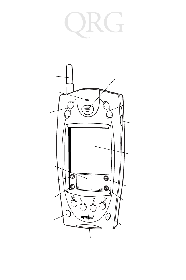
Parts of the SPT 1800
The following illustration indicates each part of the SPT 1800.
Front View
WAN Antenna
(SPT 1833/34 only)
Laser Decode LED
Scroll Button
(Up and Down)
Graffiti Input Area
Applications Icon
Center Scan Button
Scroll Button
(Up and Down)
Right Scan
Trigger
LCD (Screen)
Calculator Icon
Menu Icon
Power Button
Find Icon
Contrast Button
Application Buttons
2
Page 6
Quick Reference
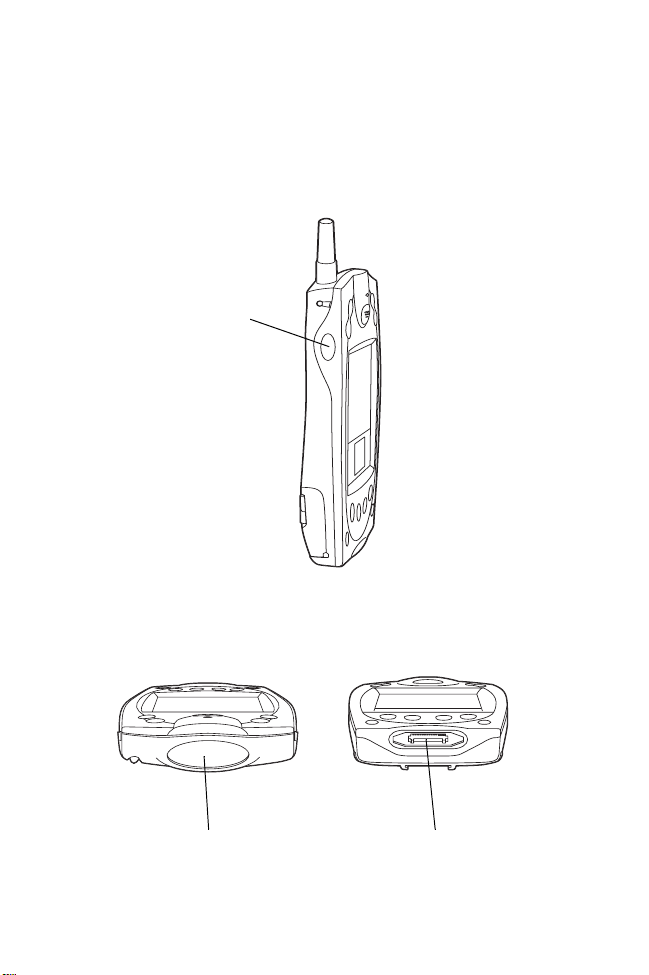
Parts of the SPT 1800 (continued)
Left View
Left Scan
Trigger
Top View
Scanner Exit Window
Bottom View
Serial Port
3
Page 7
SPT 1800 Series
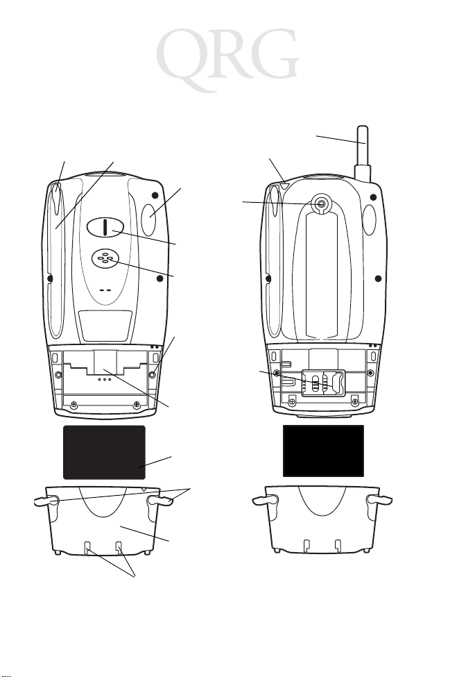
Parts of the SPT 1800 (continued)
Back View
Stylus
Stylus Silo
Headset Connector
Infrared Port
Handstrap
Connector
Handstrap
Connector
Speaker
Reset Button
Battery
Compartment
Lithium-Ion Battery
WAN Antenna
WAN Antenna
SIM Socket
Battery Latches
Battery Cover
Handstrap Connectors
4
Page 8
Quick Reference
Getting Started
Before you can use your SPT 1800, perform the basic setup
procedures:
• Install the SIM card (SPT 1834 only)
• Install and charge the battery
• Start the SPT 1800
• Initiate the network co nnection (SPT 183X/184X only).
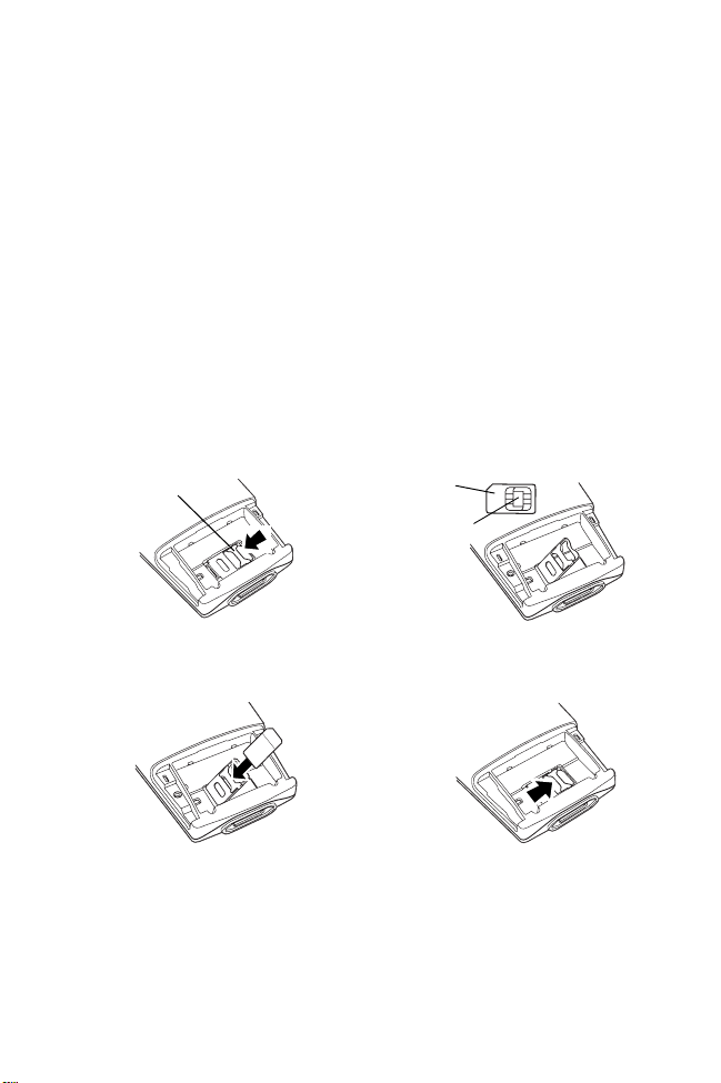
Installing the SIM Card (SPT 1834 Only)
Open the latches on the battery cover and lift it away from the
SPT1834.
Metal Clip
1. Slide the metal clip to the left
to release the SIM cardholder.
3. Insert the card between the
cardholder body and the metal
clip; be sure the beveled
corner of the SIM card is on
the top.
SIM Card
Contact Area
2. Lift the cardholder to an
upright position.
4. Close the cardholder (with the
contact area of the card facing
down.
5. Slide the metal clip to the
right to lock it in place.
5
Page 9
SPT 1800 Series
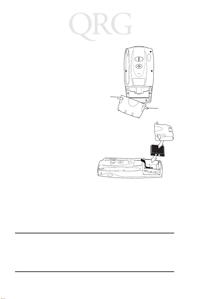
Installing the Battery
1. Open the latches on the
battery cover and lift it
away from the SPT 1800.
2. Insert the lithium-ion (L iion) battery into the battery
compartment, ensuring
that it snaps into place.
3. Replace the battery cover
and close the latches.
Note: Keep the battery
latches completely
open while securing
the battery cover.
Charging the Battery
Note: The SPT 1800 battery (p/n 20-36098-01) must be us ed
only with the SPT 1800.
Latch
Latch
Before using your SPT 1800 for the first time, charge the battery
using the cradle, the Synchro niz ati on /Charging Cable or the
Universal Battery Charger (UBC). For instructions on using the
UBC, see the
Caution: The main battery charge s the bac ku p battery in the
UBC Quick Reference Guide
SPT 1800. Once the batte ry i s full y c ha rge d, do no t remove it from the SPT 1800 for 24 hours. During thi s period, the SPT 1800 can not maintain any u ser data if the
battery is removed from the terminal.
6
.
Page 10
Quick Reference
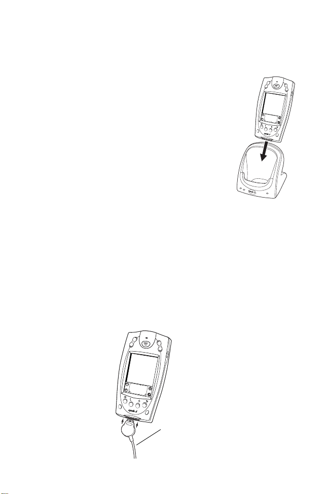
Using the Cradle to Charge the Battery
1. Ensure the battery is installed in the
terminal.
2. Plug the cradle into a wall ou tle t.
3. Insert the SPT 1800 into the cradle.
The terminal’s batt ery is fully charged after
approximately two h ours. Y ou can al so charge a
spare battery by insert ing it into th e s pare
battery charging slot on the back of the single
slot cradle . The spare bat tery fully charges in
approximately two hours. See the
Cradle Quick Refere nc e Guide
CRD 1700
for more information.
Note: When the battery is full y charged, the cradle’s charging
LED lights green. On older CRD 1700 single slot and
modem cradles, the charging LED may not illuminate
green when the terminal’s battery is fully charged.
Using the Synchronization/Charging Cable to Charge the
Battery
1. Ensure the battery is installed in the terminal.
2. Insert the cable into the bottom of the terminal.
Synchronization/
Charging Cable
7
Page 11

SPT 1800 Series
3. Plug the power cabl e into a wall o utlet and plug the other end
into the battery charging receptacle on the side of the Synchronization/Charging Cable.
Battery
Power
Supply
Charging
Receptacle
Serial Cable
The battery is fully charged after approximately two hours.
Starting the SPT 1800
Press the red power bu tton to power on the terminal. If the term inal
does not power on, perform a hard rese t. See
on page 12.
Reset
Calibrati n g the Screen
The first time you start your SPT 1800, the Welcome utility
appears. Follow the steps to align the internal ci rcuitry of your SPT
1800 with its touch-sensitive screen, and to set the current time
and date.
Note: If your SPT 1800 unit came pre-loaded with a custom
software application, you may not need to calibrate
your screen, in which case you will not see the Welcome utility.
Performing a Hard
8
Page 12

Quick Reference
1. Press the power button on the front panel of yo ur SPT 1800
to display the Welc ome util ity. (This also displays f ollowing a
hard reset).
Power
Button
Note: If necessary, adjust the contrast control on the SPT
1800 so the scree n is clear and rea dable. See
Control
2. Follow the instructions on the screen.
3. Tap the exact center of each target
that appears on the scree n with the
tip of the stylus.
If, at any time, you need to recali brate the
screen, open the
application, tap
corner of the screen, and select the
digitizer
option from the pull down menu.
on page 10 for instructions.
Preferences
General
on the top right
Contrast
Using the SPT 1800
Power Button/Backlight Control
The power button turns the SP T 1800 on an d off. This button also
serves as your backlight control for low-light conditions. When the
SPT 1800 is on, press and hold the power button for
approximately two seconds to turn the backlight on and off.
9
Page 13

SPT 1800 Series
Contrast Control
The contrast contro l button i s located o n the lower right-hand side
of the SPT 1800.
Contrast
Control
1. Press the contrast control button to display the contrast adjusting bar on the screen.
2. Using your stylus, adjust the contrast by scrolling the contrast bar until the contrast is set to the desired level, or use
either of the scroll buttons on the top of the termin al to adjust
the contrast level.
3. Press the contrast control but ton or tap Done on the screen
to turn off the contrast control.
Writing with the Stylus
Y our SPT 1800 incl udes Graffiti® handwriting software for enter ing
text and numbers. Graffiti translates stylus strokes into letters or
numbers. See the
51337-xx for more information .
SPT 1800 Product Reference Guide,
p/n 72-
On-screen Keyboar d
You can activate the on-screen keyboard any time you need to
enter text or numbers on your SPT 1800. Note that you cannot
enter Graffiti characters while using the on-screen keyboard.
1. Open any applicatio n.
New
2. Tap any record name, or tap the
the stylus.
button with the tip of
10
Page 14

Quick Reference
3. T ap the left target to open the Alpha key board, or tap the right
target to open the Numeric keyboard.
Tap here for letters
keyboard
Tap here for numbers
keyboard
Icon Descriptions
Applications Icon
Calculator Icon
Menu Icon
Find Icon
Exits the current application and li sts
available applications for selection.
Displays the calculator application.
Tap from within an application to display
the options menu for the application.
Tap from within an application to enter
search criteria to find an entry.
Using a Headset (SPT 1834 O n ly )
To use a headset with the SPT 1834, plug
the headset jack into the au di o connector
on the top of the terminal
11
Page 15

SPT 1800 Series
Resetting the SPT 1800
If your SPT 1800 stops responding to input, you may need to
perform a reset.
Performing a Soft Reset
A soft reset restarts the SPT 1800
and saves all recor ds and entries
stored in your SPT 1800 termina l.
After a soft reset, the Palm
Computing Platform® Logo screen
appears followed by the G ene ral
Preferences screen.
To perform a soft reset, remove the
battery cover and gently pre ss the
reset button located under the bat tery co ver.
Performing a Hard Reset
A hard reset also restarts your termin al, but erases all records and
entries stored in your SPT 1 800.
reset unless a soft reset does not solve your problem.
Note: Y ou can restore an y data previ ously synch ronized wi th
your computer during the next HotSync operation.
Therefore, never perform a h ard
Reset button
1. Remove the battery cover.
2. Hold down the power butt on on the front of the SPT 1800,
and gently press the rese t button.
3. Release the reset button, then release the power button
when the Palm logo appea rs.
4. When a message appea rs on the sc reen w arn ing that you
are about to erase all data, do one of the following:
a. Press the upper half of a scroll button to complete the
hard reset.
b. Press any other button to perform a soft reset.
12
Page 16

Quick Reference
Note: With a hard reset, the current date and time are re-
tained. Formats, preference s and other settings are restored to their factory defaul t setti ngs .
Attaching the Handstrap
The SPT 1800 has a hands trap w hi ch inc rea ses comfort when
holding it for extended periods of time.
1. Thread round metal piece
through this connector.
2. Slide flat metal piece up and into
this connector.
3. Adjust the velcro strap to fit your
hand.
To attach the handstrap for the SPT 1834:
1. Put the side slots of the thre ad ed button over the wire clips on
the handstrap.
2. Screw the button into the
threaded slot on the back of the
terminal.
3. Slide the flat metal piece into
the handstrap connection on
the bottom of the terminal.
13
Page 17
SPT 1800 Series
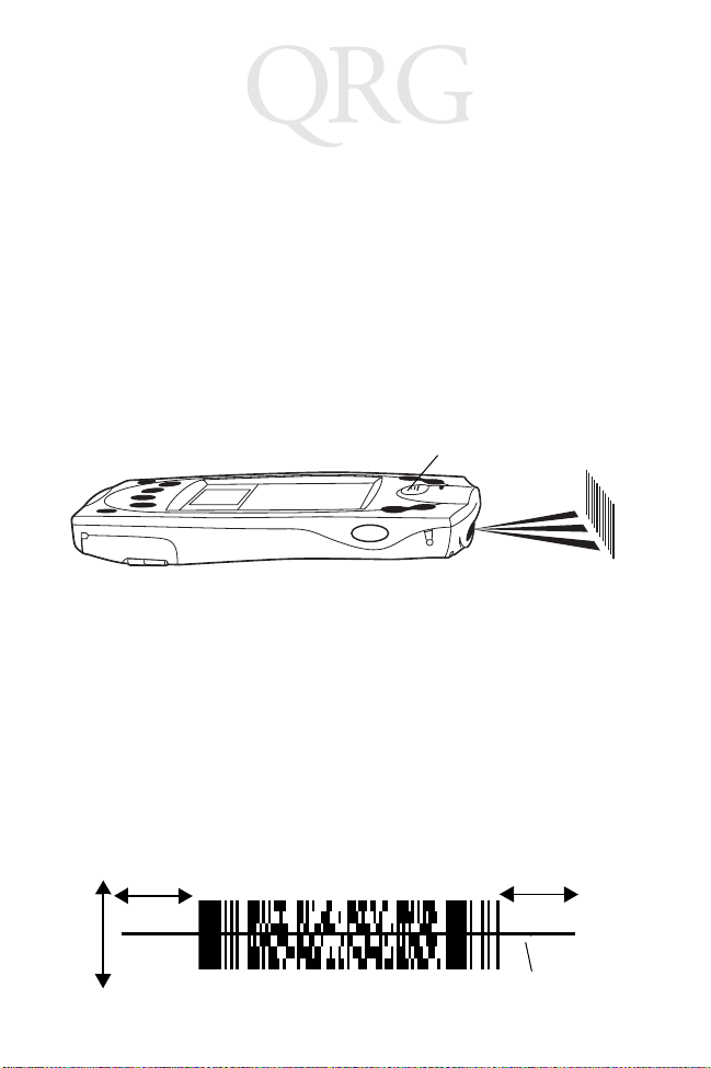
Scanning 1-D Bar Codes
The SPT 1800 has an integrated laser bar code scanner which
allows you to collect data by scanning bar co des if your unit is
configured with a scanning application. To scan bar codes:
1. Start your scanning application.
2. Aim the scanner at a bar code.
3. Press either the right, left or center scan trigger. Make sure
the red scan beam covers the entire bar code. The green
scan LED lights and a beep sound s to indic ate a succ essfu l
decode.
Center Scan Button
Scanning PDF417 (2-D) Bar Codes
To scan a PDF417 bar code (with a 2-D configured terminal):
1. Aim the scanner at the PDF bar code and press either the
right, left, or center scan trigger.
2. Hold the trigger down an d keep th e sca n line parallel to the
rows of the symbol.
3. Manually raster the scan line by slowly moving the scanner
up and down so it scans th e en tire bar code at a rate of one
inch per second.
1/2”
1/2”
Scan Line
14
Page 18

Quick Reference
A clicking noise le ts you k now the 2- D bar code i s being d ecoded.
If there is no clicking noise when you are scanning, the bar code
is not being scanned prope rly.
When decoding a very long 2-D ba r code , you may notic e a sl ight
delay between the time when the terminal completes the decode
and the time when the data is displayed on the screen. The first
beep you hear indicates a successful decode. The second beep
you hear indicates the dat a has be en recei ved by the host. Do not
attempt to decode another bar code until you hear the secon d
beep and see the green LED indicati ng a suc ces s ful dec od e.
To improve PDF decoding:
• Check that PDF417 scanning is enabled.
• Make sure the scan line extend s at least 1/2” past the left and
right edges of the bar code.
• Hold the scanner c loser for dens er symbols, f arther away fo r
larger symbols.
• Make sure you scan the top and bott om row s of the symbol.
• Be patient - it may take a few swipes to decode the symbol.
The bar code is completely decoded when you hear a tone,
followed by a short, high tone beep. The green LED stays lit for
three seconds or until the next trigger pull.
Initiating a Network Connection
Before using the term inal, set u p the Spectrum 24, CDPD (Cell ular
Digital Packet Data) or GSM (Global System for Mobile
Communication) network connection. Refer to the
Series Product Reference G uid e
instructions.
A small cursor blinks at t he top righ t-ha nd corner of the screen
when the terminal activates a radio connection (Spectrum24 or
CDPD). A blinking cursor does not appear for a GSM radio
, p/n 72-51337-xx for setup
SPT 1800
15
Page 19

SPT 1800 Series
connection. A cursor does not appear if you are not connected to
the radio.
Maintaining the SPT 1800
For trouble-free service, ob serve the following tips when using
your SPT 1800:
• Do not scratch the screen . Use the s uppli ed styl us or a pl astic-tipped pen intend ed for use with a touch-se nsitive screen.
Never use a pen or pencil or other sharp object on the
screen.
• Although your SPT 1800 is water and dust resistant, do not
expose it to rain or moisture for an ext ended period. Treat
your SPT 1800 as you would a pocket ca lc ula tor or ot her
small electronic ins t ru ment.
• The touch-sensitiv e screen of your SP T 1800 contains glass.
Do not subject your SPT 1800 to any strong impact.
• Protect your SPT 1800 from temperature extremes. Do not
leave it on the dashboard of a car on a hot day, and keep it
away from heaters and ot her heat sources.
• Do not store or use your SPT 180 0 in any loc ation th at is extremely dusty, damp or wet.
• If the surface of the SPT 1800 screen becomes soiled, clean
it with a soft lens cloth moistened with a diluted windowcleaning solution.
16
Page 20

Quick Reference
Troubleshooting
Problem Cause Solution
SPT 1800 terminal
does not turn on.
Low battery warning
after replacing the
battery.
No sound. Sound setting is
SPT 1800 terminal
turns itself off.
Contrast is set
too light.
Battery is not fully charged.
Battery is defective.
A normal condition.
set to off in the
Preferences
tion.
Terminal automatically turns itself off after a
period of inactivity.
sec-
Adjust the contrast control.
Make sure the battery is fully charged
and installed proper ly.
Replace the battery. If your SPT 1800
terminal still does not operate, try a
soft reset; see
on page 12.
The battery warning message may appear immediately after replacing the
battery. In addition, if you check the
battery gauge in the Applications
Launcher
the battery, the gauge may start at
“empty” and slowly rise to “full.” This is
normal. It takes a minute for the battery
gauge to acc urately show the condit ion
of the battery.
Check the S ound option s in t he Gen eral Preferences screen. If an option is
set to off, there will be no sound. Tap
the “off” setting to display a me nu of
options and tap the option you want.
Your SPT 1800 is designed to turn itself off after a period of inactivity. This
period can be set at thirty seconds,
one minute, two minutes or three minutes. Check the “Auto-off after” setting
in the General Preferences screen,
and change the setting if you need a
longer delay before the automatic
shutoff feature activates. See the
1800 Product Reference Guide
more information.
Note: The terminal also turns itself off
when the battery power is extremely
low.
Resetting the SPT 1800
immediately
after replacing
for
SPT
17
Page 21

SPT 1800 Series
Problem Cause Solution
SPT 1800 doesn’t
recognize my handwriting.
Tapping the screen
buttons or icons
does not activate the
corresponding feature.
When I tap the Menu
icon, nothing happens.
Beamed data does
not transmit.
When receiving
beamed data an out
of memory message
appears.
You are not using
Graffiti character
strokes.
You are not writing character
strokes in the
correct area.
Graffiti is shifted
into extended or
punctuation
modes.
Screen is out of
calibration.
Application does
not have menu
item.
Terminals are too
far apart or obstructed. File is
locked.
Memory full. Your SPT 1800 terminal requires at
For your SPT 1800 to recognize handwriting input with the stylus, you need
to use the Graffiti
SPT 1800 Prod uc t Refe r en c e
See the
Guide
for information about how to
write Graffiti character strokes.
Make the Graffiti character strokes in
the Graffiti writing area — not on the
display part of the screen.
Make sure you are writing the strokes
for letters in the left-hand side, and the
strokes for numbers in the right-hand
side of the Graffiti writing area.
SPT 1800 Prod uc t Refe r en c e
See the
Guide
for information about shifting
into and out of punctuation modes.
Recalibrate the digitizer. Choose Digitizer from the Preferences application
pick list and follow the directions on the
screen.
Not all applications or screens have
menus. Try changing to a different application.
Confirm that the SPT 1800 termina ls
are 5” apart, the receiver has its IrDA
capability enabled, and that the path
between the two devices is clear of obstacles.
Note: You cannot overwrite a .prc file
via IrDA if it is locked.
least twice the amount of memory
availabl e as the data you ar e receiving.
For example, if you are receiving a 30K
application, you mu st have at least
60K free.
®
character strokes.
18
Page 22

Quick Reference
Problem Cause Solution
SPT 1800 does not
accept scan input.
Scan application
not present.
Bad bar code. Check to be sure the ba r code symbol
Too far away
from bar code .
Bar code type is
not enabled.
Beep is not enabled.
Battery is low. If the scanner stops emitting a laser
Verify that the SPT 1800 is loaded with
a scanning application. See your System Administrator.
is not defaced.
Be sure you are within proper scanning
range.
Be sure the SPT 1800 is programmed
to accept the type of bar code you are
scanning.
If you are expecting a beep on a good
decode and don’t hear one, check that
the application is set to generate a
beep on good decode.
beam when you press the trigger,
check your battery level. When the battery is low, the scanner shuts off before
the terminal notifies you of the low battery condition.
Note: If, after performing these checks,
the scanner is still not reading symbols, contact your distributor or Symbol
Technologies.
Ergonomic Recommendations
Caution: In o rder to av oid or min imize the po tent ial ri sk of ergo nomic injur y fo llow t he
recommendations below. Consult with your local Health & Safety Manager to ensure
that you are adhering to your company’s safety programs to prevent employee injur y.
• Reduce or eliminate repet it ive moti o n
• Maintain a natural positi on
• Reduce or eliminate excessive force
• Keep objects that are used frequ ently within easy reach
• Perform tasks at correct heights
• Reduce or eliminate vibratio n
• Reduce or eliminate direct pressure
• Provide adjustabl e workstations
• Provide adequate clearance
• Provide a suitable wor k ing environment
• Improve work procedures.
19
Page 23

SPT 1800 Series
Regulatory Information
Radio Frequency Interference Requirements
This device has been tested and found to comply with the limits for a Class B digital
device pursuant to Part 15 of the Federal Communications Commissions Rules and
Regulations. These limits are designed to provide reasonable protection against
harmful interference when the equipment is operated in a commercial environment.
This equipment generates, uses, and can radiate radio frequen cy ener gy an d, if not
installed and used in accordance with the instruction manual, may cause harmful
interference to radio communications. Operation of this equipment in a residential
area is likely to cause harmful interference in which case the user will be required to
correct the interference a t hi s own expense.
However, there is no guarantee that interference will not occur in a particular
installation. If the equipment does cause harmful interference to radio or television
reception, which can be determined by turning the equipment off and on, the user is
encouraged to try to correct the inte rfe re nce by one or mor e of the foll owin g
measures:
• Re-orient or relocate the receiving antenna.
• Increase the separatio n betwe en the equ i pment and receiver.
• Connect the equipment i nto an ou tl et on a circu it d ifferent fro m that on which
the receiver is connected.
• Consult the dealer or an experienced radio/TV technician for help.
This device complies with FCC Part 15. Operation is subject to the following two
conditions: (1) this device may not cause harmfu l interf e rence and (2) this device
must accept any interference received, including interference that may cause
undesired operation.
Important Note: To comply with FCC and Industry Canada RF exposure
requirements, this hand-held device is approved for operation in a us er' s hand when
there is 20 cm or more between the antenna and the user's body.
Radio Frequency Interference Requirements - Canada
This device complies with RSS 210 of Industry & Science Canada. Operati on is
subject to the following tw o cond iti on s: (1) this devi ce ma y not cause harmful
interferenc e and (2) this device must accept any interference received, including
interference that may cause undesired operation.
This Class B digital apparatus complies with Canadian ICES-003.
Cet appareil numérique de la classe B est conforme à la norme NMB-003 du Canada.
20
Page 24

Quick Reference
CE Marking and European Union Compliance
Products intended for sale within the European Union are marked with
the CE Mark which indicates compliance to applicable Directives and
European Normes (EN), as follows. Amendments to these Directives or
ENs are included:
Applicable Directives
• Electromagnetic Compatibility Directive 89/336/EEC
• Low Voltage Directive 73/23/EEC
Applicable Standards
• EN 55022:1998, Limi ts and Met hod s of Me asu rem en t of R ad io D istu rba nce
Characteristics of Information Technology Equipment
• EN 55024:1998; Information Technology equipment - Immunity characteristics Limits and methods of measurement
• IEC 1000-4-2:1995; Electromagnetic compatibility (EMC); Part 4:Testing and
measurement techniques; Section 4.2:Electrostatic discharge immunity test
• IEC 1000-4-3:1997; Elect rom ag ne tic Compatibility (EMC); Part 4:Testing and
measurement techniques; Section 3. Radiated, radio frequency, electromagnetic field immunity test.
• IEC 1000-4-4:1995; El ectromagnetic compatibility (EMC); Part 4: Testing and
measurement techniques; Section 4:Testing electrical fast transient,/Burst
immunity.
• IEC1000-4-5:1995; Electromagnetic compatibility (EMC), Part 4: Testing and
measurement techniques; Section 5: Surge Immunity
• IEC 1000-4-6:1996; Electromagnetic compatibility (EMC), Part 4:Testing and
measurement techniques; Section 6: Immunity to conducted disturbances,
induced by radio frequency fields.
• IEC 1000-4-11:1994; Electromagnetic compatibility (EMC), Part 4: Testing and
measurement techniques; Section 11: Voltage Dips, Short Interruptions, and
Voltage Variations.
• EN 60 950 + A1+A2+A3+A4+A 11 - Safety of Information Technology Equipment Including Electrical Business Equipment
• EN 60 825-1 (EN 60 825) - Safety of Devices Containing Lasers
RF Devices
Symbol’s RF products are designed to be compliant with the rules and regulations in
the locations into which they are sold and will be labeled as required. The majority of
Symbol’s RF d evic es ar e t ype app rove d an d do not re qui re th e us er to obt ain l ice nse
or authorization before using the equipment. Any changes or modifications to Symbol
T echnologies equipment not expressly approved by Symbol Technologies could void
the user’s authority to operate the equipment.
The Spectrum24 equipment is intended for use throughout the European Economic
Area, but its authorization for use in France is restricted as follows:
21
Page 25

SPT 1800 Series
• PAN European Frequency Range: 2.400 - 2.4835 GHz, identified by -EU suffix
to the model number found on the product label.
• France - Restrict Frequency Range for use in France: 2.4465 - 2.4835 GHz,
identified on SPT 1842 by the -F R suffix to the mo del number found on the
product label.
• Belgium - Operation in an out-of-doors environment in Belgium must be
restricted to 2.460 - 2.48 35 GHz band .
• Italy - Operation in Italy requires a user license.
ARNING
W
To satisfy FCC RF exposure compliance requirements for a portable transmitting device, this device should be used in hand-held, hand-operated configurations only. The device and its antenna should gene rally maintain a
separation distance of 20cm or mo re from a person’s body; except for the
hands and wrists because of higher exposure limit for extremities. This device
is designed to be used in a person’s hands and its operating configurations
generally do not support normal transmissions while it is carried in pockets or
holsters next to a person’s body.
: FCC RF E
XPOSURE GUIDELINES
GSM Regulatory Warnings
Emergency Calls
Please contact your service provider for informa tion abo ut the availability of
Emergency Calls.
The GSM version supports Emergency Calls with or without a SIM card fitted.
However, as for any other voice call, you must be registered on a GSM network. If
you are outside the coverage of a GSM network, or another factor such as insufficient
power occurs, then Emergency Call will not work.
The procedure for generating an Emergency Call will depend on the application/
service currently in use and the network you are connected to. It is recommended that
you familiarize yourse lf wi th the app ro pri a te pro ced ures required to generate an
Emergency Call.
When connected to the Emergency Operator you should have details of you r
telephone number and location on hand.
Safety Information
The GSM version emits radio frequency signals in the 900 MHz, 1800 MHz and 1900
MHz frequency bands. The following recommendations are in line with guidelines
concerning public exposure to radio frequency electromagnetic energy, issued by
various European and International agencies.
Unlike a mobile phone, the transmitter antenna on the GSM version would not (under
normal circumstances) be close to the head, and therefore high field strength is not
usually encountered. The use of the GSM version is similar to using a mobile phone
with a handsfree unit. However, take care to avoid placing any part of your body in
proximity to the GSM version ant enna when the GSM radio is sw itched on. In
22
Page 26

Quick Reference
particular, it is recommended that you do no t grasp the an tenna while the GSM
version is operating as this will not only significantly degrade its performance, but also
expose your hand to the maximum radio frequency power emitted by the GSM
version.
Safety on the Road
The GSM version should not be used by the driver of a vehicle when in motion.
Always safely park your vehicle before turning your attention to your device. Always
adequately secure your device in a moving vehicle, and do not leave it loose on a
passenge r se a t. Re m em be r t hat in th e ev ent o f a sudden st op an unsecur ed device
could cause injury to any occupants as well as damage to the vehicle. If your vehicle
has an airbag, do not place any objects, including your device, in the area around the
airbag or where the airbag deploys. Any item propelled by an activated airbag could
cause serious injury and damage.
When receiving calls on a public highway, mobile units are not permitted to use
“warning” devices, which permit the vehicles' horn to sound or the light to flash.
Safety on Aircraft
You are required by law to switch off all electrical apparatus when boarding and
leaving an aircraft and at any other time when instructed to do so by a member of the
crew. You are not allowed to use any mobile phone, as well as the GSM version, at
any time when on board an aircraft, as such use may constitute a danger. In such
circumstances please ensure that your GSM version is switched off, disabling
attempts to log onto networks.
Pacemakers
It is recommended by pacemaker manufacturers that a minimum of 20cm (8 inches)
be maintained between a handheld wireless phone and a pacemaker to avoid any
possible interference with the pacemaker. These recommendations are consistent
with the independent research by and recommendations of Wireless Technology
Research.
Hearing Aids
Some digital wireless phones may inte rfere wit h some h e aring aids. In the event of
such interference you may want to consult your hearing aid supplier to discuss
solutions.
Persons with pacemakers:
• Should always keep the ph on e more th an 20cm (8 inches) from their pacemaker when the phone is turned on.
• Should not carry the phone in a breast pocket.
• Should use the ear opposite the pacemaker to minimize the potential for inter-
ference.
23
Page 27

SPT 1800 Series
If you have any reason to suspect that interference is taking place, turn off the GSM
version immediately. This may be achieved most rapidly by switching off the device
using its on/off button.
Other Medical Devices
The GSM version transmits radio frequency energy and as such has the potential to
interfere with inadequately protected medical devices. Consult your physician or the
manufacturer of the device to see if any particular device has sufficient protection.
It is good practice to com plet el y turn off the GS M ver s ion wi thin a hosp it al o r other
medical facility where sensitive medical equipment is in use. In some countries, this
is a legal requirement applying to all mobile phones and related equipment.
Effect on Vehicles
RF signals may affect improperly installed or inadequately shielded electronic
systems in motor vehicles (including safety systems). Check with the manufacturer
or its representative regarding your vehicle. You should also consult the manufacturer
of any equipment that has been added to your vehicle.
Posted Fa cilities
Switch off the GSM version in any facility where posted notices require mobile phones
to be switched off.
Potentially Hazardous Atmospheres
Do not take a GSM version into any area with a potentially hazardous atmosphere.
The GSM version is not rated fo r use in such environments and therefor e such use
may pose a threat of explosion.
Such areas are often, but not always, clearly marked. They may include below decks
on boats; chemical transfer or storage facilities; fuel filling stations; areas where fuel
odors are present such as in a tent or caravan where cooking or heating by bottled
gas is taking place; fuel transfer or storage facilities; vehicles using liquid petroleum
gas (lpg); areas where the air contains concentrations of grain, dust or metal
powders; and any area where you would normally be advised to turn off your vehicle
engine.
Blasting Areas
To avoid interference with any blasting operations, turn off your GSM version when in
a blasting area and other areas where the use of radio equipment is prohibited. Obey
all signs and instructions.
Laser Devices
Symbol products using lasers comply with US 21CFR1040.10, and IEC825-1:1993,
EN60825-1:1994+A11:1996. The laser classification is marked on one of the labels
on the product.
24
Page 28

Quick Reference
Class 1 Laser devices are not co nsi de red to be hazardous when used for their
intended purpose. Th e following statement is required to comply with US and
international regulations:
Caution: Use of controls, adjustments or performance of procedures other than those
specified herein ma y result in hazardous laser lig ht exposur e.
Class 2 laser scanners use a low power, visible light diode. As with any very bright
light source, such as the sun, the user should avoid staring directly into the light
beam. Momentary expo sure to a Class 2 laser is not known to be harmf ul.
Battery Caution
Caution: Danger of explosion if battery is incorrectly replaced. Replace only with
the same or equivalent type recomm end ed by the ma nufacturer. Dispose of used batteries according to the manufacturer's instructions.
Scanner Labeling
SPT 1800 SPT 1834
25
Page 29

SPT 1800 Series
In accordance with Clause 5, IEC 0825 and EN60825, the following information is
provided to the user:
ENGLISH HEBREW
CLASS 1 CLASS 1 LASER PRODUCT
CLASS 2 LASER LIGHT
DO NOT STARE INTO BEAM
CLASS 2 LASER PRODUCT
DANISH ITALIAN
KLASSE 1 KLASSE 1 LASERPRODUKT CLASSE 1 PRODOTTO AL LASER DI CLASSE 1
KLASSE 2 LASERLYF CLASSE 2 LUCE LASER
SE IKKE IND I STRÅL EN NON FISSARE IL RAGGIOPRODOTTO
KLASSE 2 LASERPRODUKT AL LASER DI CLASSE 2
DUTCH NORWEGIAN
KLASSE 1 KLASSE-1 LASERPRODUKT KLASSE 1 LASERPRODUKT, KLASSE 1
KLASSE 2 LASERLICHT KLASSE 2 LASERLYS IKKE STIRR INN I LYSSTRÅLEN
NIET IN STRAAL STAREN LASERPRODUKT, KLASSE 2
KLASSE-2 LASERPRODUKT
FINNISH PORTUGUESE
LUOKKA 1 LUOKKA 1 LASERTUOTE CLASSE 1 PRODUTO LASER DA CLASSE 1
LUOKKA 2 LASERVALO CLASSE 2 LUZ DE LASER NÃO FIXAR O RAIO LUMINOSO
ÄLÄ TUIJOTA SÄDETTÄ PRODUTO LASER DA CLASSE 2
LUOKKA 2 LASERTUOTE
FRENCH SPANISH
CLASSE 1 PRODUIT LASER DE CLASSE 1 CLASE 1 PRODUCTO LASER DE LA CLASE 1
CLASSE 2 LUMIERE LASER CLASE 2 LUZ LASER
NE PAS REGARDER LE RAYON FIXEMENT NO MIRE FIJAMENTE EL HAZ
PRODUIT LASER DE CLASSE 2 PRODUCTO LASER DE LA CLASE 2
GERMAN SWEDISH
KLASSE 1 LASERPRODUKT DER KLASSE 1 KLASS 1 LASERPRODUKT KLASS 1
KLASSE 2 LASERSTRAHLEN KLASS 2 LASERLJUS STIRRA INTE MOT STRÅLEN
NICHT DIREKT IN DEN LASERSTRAHL SCHAUEN LASERPRODUKT KLASS 2
LASERPRODUKT DER KLASSE 2
26
Page 30

Quick Reference
DECLARATION OF CONFORMITY
We, Symbol Technologies, Inc.
of One Symbol Plaza, Holtsville, NY 11742-1300, USA
declare under our sole responsibility that the p roduct(s)
Spectrum24, LA302T, Type II Radio Card
Spectrum24HR, LA411T, Type II Radio Card
Spectrum24HR, LA412T, Type II Radio Card
to which this declaration relates, are in conformity with the following standards and/or other normative documents.
ETS 300 328 (November 1996)
ETS 300 826 (November 1997)
EN 60950: 1992 Incl Amdt 1-4, 11
We hereby declare that all essential radio test suites have been carried out and that the above named products are in
conformity with all the essential requirements of Directive 1999/5/EC.
The conformity assessment procedure referred to in Article 10(5) and detailed in Annex IV of
Directive 1999/5/EC has been followed with the involvement of the following Notified Body(ies):
BABT, Claremont House, 34 Molesey Road, Walton-on-Thames, KT12 4RQ
Identification mark: 0168 The equipment will also carry the Class
The technical documentation relevant to the above equipment can be made available for
inspection on application to:
Symbol Technologies EMEA, Symbol Place, Winnersh Triangle, Berkshire, RG 41 5TP, UK
Dornu Narnor
(name)
Director, Regulatory and Technical Sales
(title)
(signature of authorised person) (date)
2 equipment identifier
3, May 2000
27
Page 31

SPT 1800 Series
28
Page 32

Quick Reference
Warranty
Symbol Technologies, Inc. (“Symbol”) manufactures its hardware products in accordance with
industry-standard practices. Symbol warrants that for a period of twelve (12) months from date of
shipment, products will be free from defects in materials and workmanship.
This warranty is provided to th e ori ginal owner only an d is not tr ansferable to any thir d party. It shall
not apply to any product (i) whi ch has been repair ed or altered un less done or appr oved by Symbol,
(ii) which has not been maintained in accordance with any operating or handling instructions
supplied by Symbol, (iii) which has been subjected to unusual physical or electrical stre ss, misuse,
abuse, power shortage, negligence or accident or (iv) which has been used other than in
accordance with the product operating and handling instructions. Preventive maintenance is the
responsibility of customer and is not covered under this warranty.
Wear items and accessories having a Symbol serial number, will carry a 90-day limited warranty.
Non-serialized items will carry a 30-day limited warranty.
Warranty Coverage and Procedure
During the warranty period, Symbol will repair or replace defective products returned to Symbol’s
manufacturing plant in the US. For warranty service in North America, call the Symbol Support
Center at 1-800-653-5350. International customers should contact the local Symbol office or
support center. If warranty service is required, Symbol will issue a Return Material Authorization
Number. Products must be shipped in the original or comparable packaging, shipping and
insurance charges prepaid. Symbol will ship the repaired or replacement product freight and
insurance prepaid in North America. Shipments from the US or other locations will be made F .O.B.
Symbol’s manufacturing plant.
Symbol will use new or refurbished parts at its discretion and will own all parts removed from
repaired products. Customer will pay for the replacement product in case it does not return the
replaced product to Symbol within 3 days of receipt of the replacement product. The process for
return and customer’s charges will be in accordance with Symbol ’s Exchange Policy in ef fect at th e
time of the exchange.
Customer accepts full responsibility for its software and data including the appropriate backup
thereof.
Repair or replacement of a product during warranty will not extend the original warranty term.
Symbol’s Customer Service organization offers an array of service plans, such as on-site, depot, or
phone support, that can be implemented to meet customer’s special operationa l requirements and
are available at a substantial discount during warranty period.
General
Except for the warranties stated above, Symbol disclaims all warranties, express or implied, on
products furnished hereunder , incl uding without lim itation implied w arranties of mer chantability and
fitness for a particular purpose. The stated express warranties are in lieu of all obligations or
liabilities on part of Symbol for damages, including without limitation, special, indirect, or
consequential damages arising out of or in connection with the use or perfor mance of the product.
Seller’s liability for damages to buyer or others resulting from the use of any p roduct, shall in no way
exceed the purchase price of said product, except in instances of injury to persons or property.
Some states (or jurisdiction s) do n ot allow the exclusion or l im itati on o f incidental or consequ ential
damages, so the preceding exclusion or limitation may not apply to you.
29
Page 33

Service Information
Before you use the unit, it must be configured to operate in your facility’s network and
run your applications.
If you have a problem running your unit or using your equipment, contact your
facility’s T echnical or Systems Support. If there is a problem with the equipment, they
will contact the Symbol Support Center:
United States 1-800-653-5350 Canada 905-629-7226
United Kingdom 0800 328 2424 Asia/Pacific 337-6588
Australia 1-800-672-906 Austria 1-505-5794
Denmark 7020-1718 Finland 9 5407 580
France 01-40-96-52-21 Germany 6074-49020
Italy 2-484441 Mexico 5-520-1835
Netherlands 315-271700 Norway 66810600
South Africa 11-4405668 Spain 9-1-320-39-09
Sweden 84452900
Latin America Sales Support 1-800-347-0178 Inside US
Europe/Mid-East Distributor Operations Contact local distributor or call
Visit
http://www.symbol.com/manuals for all product manuals
+1-561-483-1275 Outside US
+44 208 945 7360
.
72-51336-01
Revision A — May 2001
Symbol Technologies, Inc. One Symbol Plaza Holtsville, NY 11742-1300
 Loading...