

Page 1

SPT 1700 Series
Product Reference Guide
Page 2

SPT 1700 Series Product Reference Guide
70-37544-03
Revision A —December 2000
2
Symbol Technologies, Inc. One Symbol Plaza, Holtsville N.Y. 11742-1300
Page 3

SPT 1700 Series
Product Reference Guide
70-37544-03
Revision A
December 2000
Page 4

1999-2000 by Symbol Technologies, Inc. All rights reserved.
No part of this publication may be reproduced or used in any form, or by any electrical or
mechanical means, without permission in writing from Symbol. This includes electronic or
mechanical means, such as photocopying, recording, or information storage and retrieval
systems. The material in this manual is subject to change without notice.
The software is provided strictly on an “as is” basis. All software, including firmware,
furnished to the user is on a licensed basis. Symbol grants to the user a non-transferable
and non-exclusive license to use each software or firmware program delivered hereunder
(licensed program). Except as noted below, such license may not be assigned,
sublicensed, or otherwise transferred by the user without prior written consent of Symbol.
No right to copy a licensed program in whole or in part is granted, except as permitted under
copyright law. The user shall not modify, merge, or incorporate any form or portion of a
licensed program with other program material, create a derivative work from a licensed
program, or use a licensed program in a network without written permission from Symbol.
The user agrees to maintain Symbol’s copyright notice on the licensed programs delivered
hereunder, and to include the same on any authorized copies it makes, in whole or in part.
The user agrees not to decompile, disassemble, decode, or reverse engineer any licensed
program delivered to the user or any portion thereof.
Symbol reserves the right to make changes to any software or product to improve reliability,
function, or design.
Symbol does not assume any product liability arising out of, or in connection with, the
application or use of any product, circuit, or application described herein.
No license is granted, either expressly or by implication, estoppel, or otherwise under any
Symbol Technologies, Inc., intellectual property rights. An implied license only exists for
equipment, circuits, and subsystems contained in Symbol products.
Symbol and the Symbol logo are registered trademarks of Symbol T echnologies, Inc. Other
product names mentioned in this manual may be trademarks or registered trademarks of
their respective companies and are hereby acknowledged.
Symbol Technologies, Inc.
One Symbol Pl aza
Holtsville, New York 11742-1300
http://www.symbol.com
ii
Page 5

Contents
About This Guide
Introduction . . . . . . . . . . . . . . . . . . . . . . . . . . . . . . . . . . . . . . . . . . . . . . . . . . . . . . . . . . . . . . . . . . . xiii
Chapter Descriptions. . . . . . . . . . . . . . . . . . . . . . . . . . . . . . . . . . . . . . . . . . . . . . . . . . . . . . . . . . . . xv
Notational Conventions . . . . . . . . . . . . . . . . . . . . . . . . . . . . . . . . . . . . . . . . . . . . . . . . . . . . . . . . . xvii
Related Documents. . . . . . . . . . . . . . . . . . . . . . . . . . . . . . . . . . . . . . . . . . . . . . . . . . . . . . . . . . . . xvii
Service Information . . . . . . . . . . . . . . . . . . . . . . . . . . . . . . . . . . . . . . . . . . . . . . . . . . . . . . . . . . . . xviii
Symbol Support Centers . . . . . . . . . . . . . . . . . . . . . . . . . . . . . . . . . . . . . . . . . . . . . . . . . . . . .xix
Warranty . . . . . . . . . . . . . . . . . . . . . . . . . . . . . . . . . . . . . . . . . . . . . . . . . . . . . . . . . . . . . . . . . . . . .xxi
Warranty Coverage and Procedure . . . . . . . . . . . . . . . . . . . . . . . . . . . . . . . . . . . . . . . . . . . . xxii
General. . . . . . . . . . . . . . . . . . . . . . . . . . . . . . . . . . . . . . . . . . . . . . . . . . . . . . . . . . . . . . . . . . xxii
Chapter 1. Getting Started with the SPT 1700
Introduction . . . . . . . . . . . . . . . . . . . . . . . . . . . . . . . . . . . . . . . . . . . . . . . . . . . . . . . . . . . . . . . . . . 1-3
Unpacking the Terminal. . . . . . . . . . . . . . . . . . . . . . . . . . . . . . . . . . . . . . . . . . . . . . . . . . . . . . . . . 1-3
Parts of the SPT 1700 . . . . . . . . . . . . . . . . . . . . . . . . . . . . . . . . . . . . . . . . . . . . . . . . . . . . . . . . . . 1-4
Getting Started with the SPT 1700 . . . . . . . . . . . . . . . . . . . . . . . . . . . . . . . . . . . . . . . . . . . . . . . . 1-6
Setting Up the Cradle. . . . . . . . . . . . . . . . . . . . . . . . . . . . . . . . . . . . . . . . . . . . . . . . . . . . . . . 1-6
Installing the Battery. . . . . . . . . . . . . . . . . . . . . . . . . . . . . . . . . . . . . . . . . . . . . . . . . . . . . . . 1-13
Charging the Battery. . . . . . . . . . . . . . . . . . . . . . . . . . . . . . . . . . . . . . . . . . . . . . . . . . . . . . . 1-14
Attaching the Handstrap. . . . . . . . . . . . . . . . . . . . . . . . . . . . . . . . . . . . . . . . . . . . . . . . . . . . 1-15
Starting the SPT 1700 . . . . . . . . . . . . . . . . . . . . . . . . . . . . . . . . . . . . . . . . . . . . . . . . . . . . . 1-16
Configuring the Spectrum24 Network (SPT 174x only) . . . . . . . . . . . . . . . . . . . . . . . . . . . . 1-20
Configuring the Wide Area Network (SPT 173x only). . . . . . . . . . . . . . . . . . . . . . . . . . . . . . 1-20
Using the SPT 1700. . . . . . . . . . . . . . . . . . . . . . . . . . . . . . . . . . . . . . . . . . . . . . . . . . . . . . . . . . . 1-21
Using the Power Button/Backlight Control . . . . . . . . . . . . . . . . . . . . . . . . . . . . . . . . . . . . . . 1-21
Using the Contrast Control. . . . . . . . . . . . . . . . . . . . . . . . . . . . . . . . . . . . . . . . . . . . . . . . . . 1-21
Writing with the Stylus . . . . . . . . . . . . . . . . . . . . . . . . . . . . . . . . . . . . . . . . . . . . . . . . . . . . . 1-22
Using the Onscreen Keyboard . . . . . . . . . . . . . . . . . . . . . . . . . . . . . . . . . . . . . . . . . . . . . . . 1-22
Icon Descriptions . . . . . . . . . . . . . . . . . . . . . . . . . . . . . . . . . . . . . . . . . . . . . . . . . . . . . . . . . 1-23
iii
Page 6

SPT 1700 Series Product Reference Guide
Symbol Palm Terminal Desktop Software. . . . . . . . . . . . . . . . . . . . . . . . . . . . . . . . . . . . . . . . . . .1-23
System Requirements . . . . . . . . . . . . . . . . . . . . . . . . . . . . . . . . . . . . . . . . . . . . . . . . . . . . . .1-24
Symbol Palm Terminal Desktop Software Installation. . . . . . . . . . . . . . . . . . . . . . . . . . . . . .1-24
Chapter 2. Network Setup
Introduction. . . . . . . . . . . . . . . . . . . . . . . . . . . . . . . . . . . . . . . . . . . . . . . . . . . . . . . . . . . . . . . . . . .2-3
Configuring a Spectrum24 Connection (SPT 174x Only) . . . . . . . . . . . . . . . . . . . . . . . . . . . . . . . .2-3
Configuring a CDPD WAN Connection (SPT 1733 Only). . . . . . . . . . . . . . . . . . . . . . . . . . . . . . . .2-8
Setup Wizard. . . . . . . . . . . . . . . . . . . . . . . . . . . . . . . . . . . . . . . . . . . . . . . . . . . . . . . . . . . . . .2-8
Maintenance Screens and Menus. . . . . . . . . . . . . . . . . . . . . . . . . . . . . . . . . . . . . . . . . . . . .2-13
Merlin Menu Options. . . . . . . . . . . . . . . . . . . . . . . . . . . . . . . . . . . . . . . . . . . . . . . . . . . . . . . . . . .2-15
Merlin Menu. . . . . . . . . . . . . . . . . . . . . . . . . . . . . . . . . . . . . . . . . . . . . . . . . . . . . . . . . . . . . .2-15
Advanced Menu. . . . . . . . . . . . . . . . . . . . . . . . . . . . . . . . . . . . . . . . . . . . . . . . . . . . . . . . . . .2-16
Help Menu . . . . . . . . . . . . . . . . . . . . . . . . . . . . . . . . . . . . . . . . . . . . . . . . . . . . . . . . . . . . . . .2-24
Configuring a GSM WAN Connection (SPT 1734 Only). . . . . . . . . . . . . . . . . . . . . . . . . . . . . . . .2-25
Chapter 3. Working with Your SPT 1700 Terminal
Introduction. . . . . . . . . . . . . . . . . . . . . . . . . . . . . . . . . . . . . . . . . . . . . . . . . . . . . . . . . . . . . . . . . . .3-3
Applications. . . . . . . . . . . . . . . . . . . . . . . . . . . . . . . . . . . . . . . . . . . . . . . . . . . . . . . . . . . . . . . . . . .3-3
Changing the Applications Launcher Display Format . . . . . . . . . . . . . . . . . . . . . . . . . . . . . . .3-4
Switching Applications. . . . . . . . . . . . . . . . . . . . . . . . . . . . . . . . . . . . . . . . . . . . . . . . . . . . . . .3 -4
Setting Preferences for Applications . . . . . . . . . . . . . . . . . . . . . . . . . . . . . . . . . . . . . . . . . . . .3-5
Displaying Applications by Category . . . . . . . . . . . . . . . . . . . . . . . . . . . . . . . . . . . . . . . . . . . .3-5
Writing Graffiti with the Stylus. . . . . . . . . . . . . . . . . . . . . . . . . . . . . . . . . . . . . . . . . . . . . . . . . . . . .3-6
Practicing Graffiti with the Memo Pad . . . . . . . . . . . . . . . . . . . . . . . . . . . . . . . . . . . . . . . . . . .3-6
Writing Letters With Graffiti . . . . . . . . . . . . . . . . . . . . . . . . . . . . . . . . . . . . . . . . . . . . . . . . . . .3-7
Writing Numbers With Graffiti . . . . . . . . . . . . . . . . . . . . . . . . . . . . . . . . . . . . . . . . . . . . . . . .3-12
Writing Punctuation Marks With Graffiti. . . . . . . . . . . . . . . . . . . . . . . . . . . . . . . . . . . . . . . . .3-13
Writing Symbols and Extended Characters. . . . . . . . . . . . . . . . . . . . . . . . . . . . . . . . . . . . . .3-14
Writing Accented Characters. . . . . . . . . . . . . . . . . . . . . . . . . . . . . . . . . . . . . . . . . . . . . . . . .3-15
Accent Strokes. . . . . . . . . . . . . . . . . . . . . . . . . . . . . . . . . . . . . . . . . . . . . . . . . . . . . . . . . . . .3-15
Additional Non-English Characters . . . . . . . . . . . . . . . . . . . . . . . . . . . . . . . . . . . . . . . . . . . .3-15
Navigation Strokes. . . . . . . . . . . . . . . . . . . . . . . . . . . . . . . . . . . . . . . . . . . . . . . . . . . . . . . . .3-15
Graffiti ShortCuts. . . . . . . . . . . . . . . . . . . . . . . . . . . . . . . . . . . . . . . . . . . . . . . . . . . . . . . . . .3-16
Using the On-Screen Keyboard . . . . . . . . . . . . . . . . . . . . . . . . . . . . . . . . . . . . . . . . . . . . . . . . . .3-17
Using Application Controls . . . . . . . . . . . . . . . . . . . . . . . . . . . . . . . . . . . . . . . . . . . . . . . . . . . . . .3-19
Using Menus. . . . . . . . . . . . . . . . . . . . . . . . . . . . . . . . . . . . . . . . . . . . . . . . . . . . . . . . . . . . . . . . .3-20
Choosing a Menu. . . . . . . . . . . . . . . . . . . . . . . . . . . . . . . . . . . . . . . . . . . . . . . . . . . . . . . . . .3-20
Graffiti Menu Commands. . . . . . . . . . . . . . . . . . . . . . . . . . . . . . . . . . . . . . . . . . . . . . . . . . . .3-21
Edit Menu Commands. . . . . . . . . . . . . . . . . . . . . . . . . . . . . . . . . . . . . . . . . . . . . . . . . . . . . .3-21
Choosing Fonts. . . . . . . . . . . . . . . . . . . . . . . . . . . . . . . . . . . . . . . . . . . . . . . . . . . . . . . . . . . . . . .3-23
iv
Page 7

Contents
Using Categories. . . . . . . . . . . . . . . . . . . . . . . . . . . . . . . . . . . . . . . . . . . . . . . . . . . . . . . . . . . . . 3-24
Using Categories in Lists . . . . . . . . . . . . . . . . . . . . . . . . . . . . . . . . . . . . . . . . . . . . . . . . . . . 3-25
Defining a New Category . . . . . . . . . . . . . . . . . . . . . . . . . . . . . . . . . . . . . . . . . . . . . . . . . . . 3-26
Renaming Categories. . . . . . . . . . . . . . . . . . . . . . . . . . . . . . . . . . . . . . . . . . . . . . . . . . . . . . 3-27
Attaching Notes . . . . . . . . . . . . . . . . . . . . . . . . . . . . . . . . . . . . . . . . . . . . . . . . . . . . . . . . . . . . . . 3-29
Marking Private Entries. . . . . . . . . . . . . . . . . . . . . . . . . . . . . . . . . . . . . . . . . . . . . . . . . . . . . 3-30
Beaming Information to Other SPT 1700 Terminals . . . . . . . . . . . . . . . . . . . . . . . . . . . . . . . . . . 3-30
Scanning with the SPT 1700 . . . . . . . . . . . . . . . . . . . . . . . . . . . . . . . . . . . . . . . . . . . . . . . . . . . . 3-32
Chapter 4. Finding Information With Your SPT 1700 Terminal
Introduction . . . . . . . . . . . . . . . . . . . . . . . . . . . . . . . . . . . . . . . . . . . . . . . . . . . . . . . . . . . . . . . . . . 4-3
Using the Find Command . . . . . . . . . . . . . . . . . . . . . . . . . . . . . . . . . . . . . . . . . . . . . . . . . . . . . . . 4-3
Using Phone Lookup . . . . . . . . . . . . . . . . . . . . . . . . . . . . . . . . . . . . . . . . . . . . . . . . . . . . . . . . . . . 4-4
Phone Lookup Tips. . . . . . . . . . . . . . . . . . . . . . . . . . . . . . . . . . . . . . . . . . . . . . . . . . . . . . . . . 4-5
Chapter 5. Applications: Address Book
Introduction . . . . . . . . . . . . . . . . . . . . . . . . . . . . . . . . . . . . . . . . . . . . . . . . . . . . . . . . . . . . . . . . . . 5-3
Opening the Address Book. . . . . . . . . . . . . . . . . . . . . . . . . . . . . . . . . . . . . . . . . . . . . . . . . . . 5-3
Address Book Entries . . . . . . . . . . . . . . . . . . . . . . . . . . . . . . . . . . . . . . . . . . . . . . . . . . . . . . . . . . 5-4
Creating an Address Book Entry . . . . . . . . . . . . . . . . . . . . . . . . . . . . . . . . . . . . . . . . . . . . . . 5-4
Deleting an Address Book Entry. . . . . . . . . . . . . . . . . . . . . . . . . . . . . . . . . . . . . . . . . . . . . . . 5-6
Duplicating an Address Book Entry . . . . . . . . . . . . . . . . . . . . . . . . . . . . . . . . . . . . . . . . . . . . 5-6
Working with Address Book Entries . . . . . . . . . . . . . . . . . . . . . . . . . . . . . . . . . . . . . . . . . . . . 5-6
Beaming Address Entries to Other SPT 1700 Terminals . . . . . . . . . . . . . . . . . . . . . . . . . . . 5-10
Address Book Menu Commands. . . . . . . . . . . . . . . . . . . . . . . . . . . . . . . . . . . . . . . . . . . . . . . . . 5-11
Record Menu . . . . . . . . . . . . . . . . . . . . . . . . . . . . . . . . . . . . . . . . . . . . . . . . . . . . . . . . . . . . 5-12
Options Menu. . . . . . . . . . . . . . . . . . . . . . . . . . . . . . . . . . . . . . . . . . . . . . . . . . . . . . . . . . . . 5-13
Chapter 6. Applications: Calculator
Introduction . . . . . . . . . . . . . . . . . . . . . . . . . . . . . . . . . . . . . . . . . . . . . . . . . . . . . . . . . . . . . . . . . . 6-3
Opening the Calculator . . . . . . . . . . . . . . . . . . . . . . . . . . . . . . . . . . . . . . . . . . . . . . . . . . . . . . . . . 6-3
Using the Calculator Screen . . . . . . . . . . . . . . . . . . . . . . . . . . . . . . . . . . . . . . . . . . . . . . . . . . . . . 6-3
Special Calculator Buttons . . . . . . . . . . . . . . . . . . . . . . . . . . . . . . . . . . . . . . . . . . . . . . . . . . . 6-3
Calculator Menu Commands . . . . . . . . . . . . . . . . . . . . . . . . . . . . . . . . . . . . . . . . . . . . . . . . . . . . . 6-4
Recent Calculations . . . . . . . . . . . . . . . . . . . . . . . . . . . . . . . . . . . . . . . . . . . . . . . . . . . . . . . . 6-5
v
Page 8

SPT 1700 Series Product Reference Guide
Chapter 7. Applications: Date Book
Introduction. . . . . . . . . . . . . . . . . . . . . . . . . . . . . . . . . . . . . . . . . . . . . . . . . . . . . . . . . . . . . . . . . . .7-3
Opening the Date Book. . . . . . . . . . . . . . . . . . . . . . . . . . . . . . . . . . . . . . . . . . . . . . . . . . . . . .7-3
Using the Date Book. . . . . . . . . . . . . . . . . . . . . . . . . . . . . . . . . . . . . . . . . . . . . . . . . . . . . . . . . . . . 7-4
Scheduling an Event . . . . . . . . . . . . . . . . . . . . . . . . . . . . . . . . . . . . . . . . . . . . . . . . . . . . . . . .7-4
Rescheduling an Event . . . . . . . . . . . . . . . . . . . . . . . . . . . . . . . . . . . . . . . . . . . . . . . . . . . . . .7-8
Setting an Alarm for an Event . . . . . . . . . . . . . . . . . . . . . . . . . . . . . . . . . . . . . . . . . . . . . . . . .7-8
Scheduling Repeating Events . . . . . . . . . . . . . . . . . . . . . . . . . . . . . . . . . . . . . . . . . . . . . . . .7-10
Marking a Private Event. . . . . . . . . . . . . . . . . . . . . . . . . . . . . . . . . . . . . . . . . . . . . . . . . . . . .7-12
Deleting an Event . . . . . . . . . . . . . . . . . . . . . . . . . . . . . . . . . . . . . . . . . . . . . . . . . . . . . . . . .7 -12
Changing the Date Book View . . . . . . . . . . . . . . . . . . . . . . . . . . . . . . . . . . . . . . . . . . . . . . . . . . .7-13
Working in Week View. . . . . . . . . . . . . . . . . . . . . . . . . . . . . . . . . . . . . . . . . . . . . . . . . . . . . .7-13
Working in Month View . . . . . . . . . . . . . . . . . . . . . . . . . . . . . . . . . . . . . . . . . . . . . . . . . . . . .7-15
Working in Agenda View . . . . . . . . . . . . . . . . . . . . . . . . . . . . . . . . . . . . . . . . . . . . . . . . . . . .7-16
Date Book Menu Commands . . . . . . . . . . . . . . . . . . . . . . . . . . . . . . . . . . . . . . . . . . . . . . . . . . . .7-17
Record Menu. . . . . . . . . . . . . . . . . . . . . . . . . . . . . . . . . . . . . . . . . . . . . . . . . . . . . . . . . . . . .7-17
Options Menu . . . . . . . . . . . . . . . . . . . . . . . . . . . . . . . . . . . . . . . . . . . . . . . . . . . . . . . . . . . .7-19
Chapter 8. Applications: Expense
Introduction. . . . . . . . . . . . . . . . . . . . . . . . . . . . . . . . . . . . . . . . . . . . . . . . . . . . . . . . . . . . . . . . . . .8-3
Opening Expense . . . . . . . . . . . . . . . . . . . . . . . . . . . . . . . . . . . . . . . . . . . . . . . . . . . . . . . . . . . . . .8-3
Using Expense . . . . . . . . . . . . . . . . . . . . . . . . . . . . . . . . . . . . . . . . . . . . . . . . . . . . . . . . . . . . . . . .8-4
Creating an Expense Item. . . . . . . . . . . . . . . . . . . . . . . . . . . . . . . . . . . . . . . . . . . . . . . . . . . .8-4
Changing the Expense Item Date . . . . . . . . . . . . . . . . . . . . . . . . . . . . . . . . . . . . . . . . . . . . . .8-5
Entering Receipt Details . . . . . . . . . . . . . . . . . . . . . . . . . . . . . . . . . . . . . . . . . . . . . . . . . . . . . 8-5
Customizing the Currency Pick List. . . . . . . . . . . . . . . . . . . . . . . . . . . . . . . . . . . . . . . . . . . . .8-8
Show Options . . . . . . . . . . . . . . . . . . . . . . . . . . . . . . . . . . . . . . . . . . . . . . . . . . . . . . . . . . . . . . . . .8-9
Transferring Your Data to Microsoft Excel . . . . . . . . . . . . . . . . . . . . . . . . . . . . . . . . . . . . . . . . . .8-10
Printing an Expense Report . . . . . . . . . . . . . . . . . . . . . . . . . . . . . . . . . . . . . . . . . . . . . . . . . . . . .8-10
Viewing your Expense Report in Microsoft Excel . . . . . . . . . . . . . . . . . . . . . . . . . . . . . . . . . . . . .8-12
Using Expense Report Templates . . . . . . . . . . . . . . . . . . . . . . . . . . . . . . . . . . . . . . . . . . . . . . . .8-14
Expense Menu Commands. . . . . . . . . . . . . . . . . . . . . . . . . . . . . . . . . . . . . . . . . . . . . . . . . . . . . .8-15
Record Menu. . . . . . . . . . . . . . . . . . . . . . . . . . . . . . . . . . . . . . . . . . . . . . . . . . . . . . . . . . . . .8-16
Options Menu . . . . . . . . . . . . . . . . . . . . . . . . . . . . . . . . . . . . . . . . . . . . . . . . . . . . . . . . . . . .8-17
Chapter 9. Applications: HotSync®
Introduction. . . . . . . . . . . . . . . . . . . . . . . . . . . . . . . . . . . . . . . . . . . . . . . . . . . . . . . . . . . . . . . . . . .9-3
The HotSync Process and the HotSync Manager. . . . . . . . . . . . . . . . . . . . . . . . . . . . . . . . . . . . . .9-3
Performing a HotSync Operation for the First Time . . . . . . . . . . . . . . . . . . . . . . . . . . . . . . . . . . . .9-3
Using User Profiles . . . . . . . . . . . . . . . . . . . . . . . . . . . . . . . . . . . . . . . . . . . . . . . . . . . . . . . . .9-6
Using File Link. . . . . . . . . . . . . . . . . . . . . . . . . . . . . . . . . . . . . . . . . . . . . . . . . . . . . . . . . . . . .9-8
vi
Page 9

Contents
Conducting a Local HotSync Operation. . . . . . . . . . . . . . . . . . . . . . . . . . . . . . . . . . . . . . . . . . . . . 9-9
Selecting HotSync Setup Options . . . . . . . . . . . . . . . . . . . . . . . . . . . . . . . . . . . . . . . . . . . . . . . . . 9-9
Customizing HotSync Application Settings . . . . . . . . . . . . . . . . . . . . . . . . . . . . . . . . . . . . . . . . . 9-12
Conducting a HotSync Operation via Modem . . . . . . . . . . . . . . . . . . . . . . . . . . . . . . . . . . . . . . . 9-14
Preparing Your Computer for a Modem HotSync Operation . . . . . . . . . . . . . . . . . . . . . . . . 9-14
Preparing Your SPT 1700 Terminal for a Modem HotSync Operation. . . . . . . . . . . . . . . . . 9-15
Selecting the Conduits for a Modem HotSync Operation. . . . . . . . . . . . . . . . . . . . . . . . . . . 9-16
Performing a HotSync Operation via Modem. . . . . . . . . . . . . . . . . . . . . . . . . . . . . . . . . . . . 9-17
Conducting Wireless HotSync Operations. . . . . . . . . . . . . . . . . . . . . . . . . . . . . . . . . . . . . . . . . . 9-18
Setting Up for a Wireless HotSync. . . . . . . . . . . . . . . . . . . . . . . . . . . . . . . . . . . . . . . . . . . . . . . . 9-18
Performing a Spectrum24 HotSync . . . . . . . . . . . . . . . . . . . . . . . . . . . . . . . . . . . . . . . . . . . 9-19
Performing a CDPD HotSync. . . . . . . . . . . . . . . . . . . . . . . . . . . . . . . . . . . . . . . . . . . . . . . . 9-20
Performing a GSM HotSync. . . . . . . . . . . . . . . . . . . . . . . . . . . . . . . . . . . . . . . . . . . . . . . . . 9-21
Setting Up the Ethernet Cradle for HotSync . . . . . . . . . . . . . . . . . . . . . . . . . . . . . . . . . . . . . . . . 9-22
Installing NetSync. . . . . . . . . . . . . . . . . . . . . . . . . . . . . . . . . . . . . . . . . . . . . . . . . . . . . . . . . 9-22
Creating a CRD1700-4000E Modem Sync Service . . . . . . . . . . . . . . . . . . . . . . . . . . . . . . . 9-23
Configuring the Remote Host PC for Use with the Ethernet Cradle. . . . . . . . . . . . . . . . . . . 9-24
The Ethernet HotSync Process . . . . . . . . . . . . . . . . . . . . . . . . . . . . . . . . . . . . . . . . . . . . . . 9-24
Chapter 10. Applications: ScoutSync Client
Introduction . . . . . . . . . . . . . . . . . . . . . . . . . . . . . . . . . . . . . . . . . . . . . . . . . . . . . . . . . . . . . . . . . 10-3
Overview of the ScoutSync Client . . . . . . . . . . . . . . . . . . . . . . . . . . . . . . . . . . . . . . . . . . . . 10-3
Configuring the ScoutSync Client . . . . . . . . . . . . . . . . . . . . . . . . . . . . . . . . . . . . . . . . . . . . . . . . 10-4
Selecting Conduits for Synchronization . . . . . . . . . . . . . . . . . . . . . . . . . . . . . . . . . . . . . . . . 10-5
Performing a Synchronization. . . . . . . . . . . . . . . . . . . . . . . . . . . . . . . . . . . . . . . . . . . . . . . . 10-6
Automatically Synchronizing Using a Cradle . . . . . . . . . . . . . . . . . . . . . . . . . . . . . . . . . . . . 10-6
Viewing the Synchronization Log . . . . . . . . . . . . . . . . . . . . . . . . . . . . . . . . . . . . . . . . . . . . . 10-7
ScoutSync Client Menu Commands . . . . . . . . . . . . . . . . . . . . . . . . . . . . . . . . . . . . . . . . . . . . . . 10-8
Options Menu. . . . . . . . . . . . . . . . . . . . . . . . . . . . . . . . . . . . . . . . . . . . . . . . . . . . . . . . . . . . 10-8
Chapter 11. Applications: AvantGo Client and Mobile Link
Introduction . . . . . . . . . . . . . . . . . . . . . . . . . . . . . . . . . . . . . . . . . . . . . . . . . . . . . . . . . . . . . . . . . 11-3
AvantGo Client. . . . . . . . . . . . . . . . . . . . . . . . . . . . . . . . . . . . . . . . . . . . . . . . . . . . . . . . . . . . . . . 11-3
Navigating in AvantGo Client . . . . . . . . . . . . . . . . . . . . . . . . . . . . . . . . . . . . . . . . . . . . . . . . 11-3
Icon Descriptions . . . . . . . . . . . . . . . . . . . . . . . . . . . . . . . . . . . . . . . . . . . . . . . . . . . . . . . . . 11-4
Using the Channel Manager . . . . . . . . . . . . . . . . . . . . . . . . . . . . . . . . . . . . . . . . . . . . . . . . . . . . 11-4
Updating Channel Pages . . . . . . . . . . . . . . . . . . . . . . . . . . . . . . . . . . . . . . . . . . . . . . . . . . . 11-5
Using the Forms Manager. . . . . . . . . . . . . . . . . . . . . . . . . . . . . . . . . . . . . . . . . . . . . . . . . . . . . . 11-6
Editing Forms in the Forms Manager Cue . . . . . . . . . . . . . . . . . . . . . . . . . . . . . . . . . . . . . . 11-6
Deleting Forms in the Forms Manager. . . . . . . . . . . . . . . . . . . . . . . . . . . . . . . . . . . . . . . . . 11-7
Using HTML Forms. . . . . . . . . . . . . . . . . . . . . . . . . . . . . . . . . . . . . . . . . . . . . . . . . . . . . . . . 11-7
vii
Page 10

SPT 1700 Series Product Reference Guide
Using AvantGo Client With a Modem . . . . . . . . . . . . . . . . . . . . . . . . . . . . . . . . . . . . . . . . . . . . . .11-8
Browsing Online. . . . . . . . . . . . . . . . . . . . . . . . . . . . . . . . . . . . . . . . . . . . . . . . . . . . . . . . . . .11-8
Synchronizing With a Modem . . . . . . . . . . . . . . . . . . . . . . . . . . . . . . . . . . . . . . . . . . . . . . . .11-9
AvantGo Client Menu Commands. . . . . . . . . . . . . . . . . . . . . . . . . . . . . . . . . . . . . . . . . . . . . . . .11-10
Channels Menu . . . . . . . . . . . . . . . . . . . . . . . . . . . . . . . . . . . . . . . . . . . . . . . . . . . . . . . . . .11-10
Go Menu . . . . . . . . . . . . . . . . . . . . . . . . . . . . . . . . . . . . . . . . . . . . . . . . . . . . . . . . . . . . . . .11-11
Options Menu . . . . . . . . . . . . . . . . . . . . . . . . . . . . . . . . . . . . . . . . . . . . . . . . . . . . . . . . . . .11-11
Mobile Link . . . . . . . . . . . . . . . . . . . . . . . . . . . . . . . . . . . . . . . . . . . . . . . . . . . . . . . . . . . . . . . . .11-12
Servers Tab. . . . . . . . . . . . . . . . . . . . . . . . . . . . . . . . . . . . . . . . . . . . . . . . . . . . . . . . . . . . . . . . .11-13
Edit Server Profile Panel . . . . . . . . . . . . . . . . . . . . . . . . . . . . . . . . . . . . . . . . . . . . . . . . . . . 11-14
Connection Tab. . . . . . . . . . . . . . . . . . . . . . . . . . . . . . . . . . . . . . . . . . . . . . . . . . . . . . . . . . . . . .11-16
Advanced Connection Settings . . . . . . . . . . . . . . . . . . . . . . . . . . . . . . . . . . . . . . . . . . . . . .11-17
Using the Mobile Link Application on Your SPT 173x Terminal . . . . . . . . . . . . . . . . . . . . . . . . .11-18
Mobile Link Menu Commands. . . . . . . . . . . . . . . . . . . . . . . . . . . . . . . . . . . . . . . . . . . . . . . . . . .11-21
Server Menu . . . . . . . . . . . . . . . . . . . . . . . . . . . . . . . . . . . . . . . . . . . . . . . . . . . . . . . . . . . .11-21
Options Menu . . . . . . . . . . . . . . . . . . . . . . . . . . . . . . . . . . . . . . . . . . . . . . . . . . . . . . . . . . .11-21
Troubleshooting . . . . . . . . . . . . . . . . . . . . . . . . . . . . . . . . . . . . . . . . . . . . . . . . . . . . . . . . . . . . .11-22
Chapter 12. Applications: Mail
Introduction. . . . . . . . . . . . . . . . . . . . . . . . . . . . . . . . . . . . . . . . . . . . . . . . . . . . . . . . . . . . . . . . . .12-3
Setting Up Mail on the Desktop. . . . . . . . . . . . . . . . . . . . . . . . . . . . . . . . . . . . . . . . . . . . . . . . . . .12-3
Synchronizing Mail with Your E-Mail Application . . . . . . . . . . . . . . . . . . . . . . . . . . . . . . . . . . . . .12-5
Opening Mail on Your SPT 1700 Terminal. . . . . . . . . . . . . . . . . . . . . . . . . . . . . . . . . . . . . . . . . .12-5
Viewing Messages . . . . . . . . . . . . . . . . . . . . . . . . . . . . . . . . . . . . . . . . . . . . . . . . . . . . . . . . . . . .12-5
Message Fonts . . . . . . . . . . . . . . . . . . . . . . . . . . . . . . . . . . . . . . . . . . . . . . . . . . . . . . . . . . .12-6
Displaying Full Header Information . . . . . . . . . . . . . . . . . . . . . . . . . . . . . . . . . . . . . . . . . . . .12-6
Creating Messages. . . . . . . . . . . . . . . . . . . . . . . . . . . . . . . . . . . . . . . . . . . . . . . . . . . . . . . . . . . .12-7
Looking Up an Address. . . . . . . . . . . . . . . . . . . . . . . . . . . . . . . . . . . . . . . . . . . . . . . . . . . . . . . .12-10
Adding Message Details. . . . . . . . . . . . . . . . . . . . . . . . . . . . . . . . . . . . . . . . . . . . . . . . . . . . . . .12-11
Setting a Priority . . . . . . . . . . . . . . . . . . . . . . . . . . . . . . . . . . . . . . . . . . . . . . . . . . . . . . . . .12-12
Sending a Blind Carbon Copy . . . . . . . . . . . . . . . . . . . . . . . . . . . . . . . . . . . . . . . . . . . . . . .12-12
Adding a Signature to Your Message . . . . . . . . . . . . . . . . . . . . . . . . . . . . . . . . . . . . . . . . .12-13
Sending Messages . . . . . . . . . . . . . . . . . . . . . . . . . . . . . . . . . . . . . . . . . . . . . . . . . . . . . . . . . . .12-14
Editing an Unsent Message . . . . . . . . . . . . . . . . . . . . . . . . . . . . . . . . . . . . . . . . . . . . . . . . . . . .12-15
Draft Messages. . . . . . . . . . . . . . . . . . . . . . . . . . . . . . . . . . . . . . . . . . . . . . . . . . . . . . . . . . . . . .12-16
Filing a Message. . . . . . . . . . . . . . . . . . . . . . . . . . . . . . . . . . . . . . . . . . . . . . . . . . . . . . . . . . . . .12-17
Deleting Messages . . . . . . . . . . . . . . . . . . . . . . . . . . . . . . . . . . . . . . . . . . . . . . . . . . . . . . . . . . .12-17
Restoring a Message From the Deleted Folder. . . . . . . . . . . . . . . . . . . . . . . . . . . . . . . . . .12-18
Purging Deleted Messages . . . . . . . . . . . . . . . . . . . . . . . . . . . . . . . . . . . . . . . . . . . . . . . . .12-18
Message List Options . . . . . . . . . . . . . . . . . . . . . . . . . . . . . . . . . . . . . . . . . . . . . . . . . . . . . . . . .12-19
Folders. . . . . . . . . . . . . . . . . . . . . . . . . . . . . . . . . . . . . . . . . . . . . . . . . . . . . . . . . . . . . . . . .12-19
Date Column . . . . . . . . . . . . . . . . . . . . . . . . . . . . . . . . . . . . . . . . . . . . . . . . . . . . . . . . . . . .12-20
Sorting the Message List . . . . . . . . . . . . . . . . . . . . . . . . . . . . . . . . . . . . . . . . . . . . . . . . . . .12-20
viii
Page 11

Contents
HotSync Options . . . . . . . . . . . . . . . . . . . . . . . . . . . . . . . . . . . . . . . . . . . . . . . . . . . . . . . . . . . . 12-21
Creating Special Filters. . . . . . . . . . . . . . . . . . . . . . . . . . . . . . . . . . . . . . . . . . . . . . . . . . . . 12-22
Defining Filter Strings. . . . . . . . . . . . . . . . . . . . . . . . . . . . . . . . . . . . . . . . . . . . . . . . . . . . . 12-24
High-Priority Messages. . . . . . . . . . . . . . . . . . . . . . . . . . . . . . . . . . . . . . . . . . . . . . . . . . . . 12-26
Truncating Messages . . . . . . . . . . . . . . . . . . . . . . . . . . . . . . . . . . . . . . . . . . . . . . . . . . . . . 12-26
Mail Menu Commands. . . . . . . . . . . . . . . . . . . . . . . . . . . . . . . . . . . . . . . . . . . . . . . . . . . . . . . . 12-28
Message Menu. . . . . . . . . . . . . . . . . . . . . . . . . . . . . . . . . . . . . . . . . . . . . . . . . . . . . . . . . . 12-28
Options Menu. . . . . . . . . . . . . . . . . . . . . . . . . . . . . . . . . . . . . . . . . . . . . . . . . . . . . . . . . . . 12-29
Chapter 13. Applications: Memo Pad
Introduction . . . . . . . . . . . . . . . . . . . . . . . . . . . . . . . . . . . . . . . . . . . . . . . . . . . . . . . . . . . . . . . . . 13-3
Opening the Memo Pad . . . . . . . . . . . . . . . . . . . . . . . . . . . . . . . . . . . . . . . . . . . . . . . . . . . . 13-3
Creating a New Memo. . . . . . . . . . . . . . . . . . . . . . . . . . . . . . . . . . . . . . . . . . . . . . . . . . . . . . . . . 13-4
Reviewing Memos . . . . . . . . . . . . . . . . . . . . . . . . . . . . . . . . . . . . . . . . . . . . . . . . . . . . . . . . . . . . 13-5
Arranging Memos. . . . . . . . . . . . . . . . . . . . . . . . . . . . . . . . . . . . . . . . . . . . . . . . . . . . . . . . . . . . . 13-5
Manually Arranging the Memo List. . . . . . . . . . . . . . . . . . . . . . . . . . . . . . . . . . . . . . . . . . . . 13-6
Choosing a Memo Category . . . . . . . . . . . . . . . . . . . . . . . . . . . . . . . . . . . . . . . . . . . . . . . . . . . . 13-6
Marking a Private Memo . . . . . . . . . . . . . . . . . . . . . . . . . . . . . . . . . . . . . . . . . . . . . . . . . . . . . . . 13-6
Deleting a Memo . . . . . . . . . . . . . . . . . . . . . . . . . . . . . . . . . . . . . . . . . . . . . . . . . . . . . . . . . . . . . 13-7
Memo Pad Menu Commands . . . . . . . . . . . . . . . . . . . . . . . . . . . . . . . . . . . . . . . . . . . . . . . . . . . 13-8
Record Menu . . . . . . . . . . . . . . . . . . . . . . . . . . . . . . . . . . . . . . . . . . . . . . . . . . . . . . . . . . . . 13-8
Options Menu. . . . . . . . . . . . . . . . . . . . . . . . . . . . . . . . . . . . . . . . . . . . . . . . . . . . . . . . . . . . 13-9
Chapter 14. Applications: Preferences
Introduction . . . . . . . . . . . . . . . . . . . . . . . . . . . . . . . . . . . . . . . . . . . . . . . . . . . . . . . . . . . . . . . . . 14-3
Buttons Preferences . . . . . . . . . . . . . . . . . . . . . . . . . . . . . . . . . . . . . . . . . . . . . . . . . . . . . . . . . . 14-3
Pen Preferences. . . . . . . . . . . . . . . . . . . . . . . . . . . . . . . . . . . . . . . . . . . . . . . . . . . . . . . . . . 14-5
HotSync Buttons Preferences . . . . . . . . . . . . . . . . . . . . . . . . . . . . . . . . . . . . . . . . . . . . . . . 14-6
Connection Preferences . . . . . . . . . . . . . . . . . . . . . . . . . . . . . . . . . . . . . . . . . . . . . . . . . . . . . . . 14-7
Digitizer Preferences . . . . . . . . . . . . . . . . . . . . . . . . . . . . . . . . . . . . . . . . . . . . . . . . . . . . . . . . . . 14-9
Formats Preferences. . . . . . . . . . . . . . . . . . . . . . . . . . . . . . . . . . . . . . . . . . . . . . . . . . . . . . . . . . 14-9
Country Default. . . . . . . . . . . . . . . . . . . . . . . . . . . . . . . . . . . . . . . . . . . . . . . . . . . . . . . . . . . 14-9
Time, Date, Week Start and Numbers Formats . . . . . . . . . . . . . . . . . . . . . . . . . . . . . . . . . 14-10
General Preferences . . . . . . . . . . . . . . . . . . . . . . . . . . . . . . . . . . . . . . . . . . . . . . . . . . . . . . . . . 14-10
Setting the Current Time . . . . . . . . . . . . . . . . . . . . . . . . . . . . . . . . . . . . . . . . . . . . . . . . . . 14-10
Setting the Current Date. . . . . . . . . . . . . . . . . . . . . . . . . . . . . . . . . . . . . . . . . . . . . . . . . . . 14-11
Auto-Off . . . . . . . . . . . . . . . . . . . . . . . . . . . . . . . . . . . . . . . . . . . . . . . . . . . . . . . . . . . . . . . 14-12
Stay On In Cradle. . . . . . . . . . . . . . . . . . . . . . . . . . . . . . . . . . . . . . . . . . . . . . . . . . . . . . . . 14-12
Trigger Wake . . . . . . . . . . . . . . . . . . . . . . . . . . . . . . . . . . . . . . . . . . . . . . . . . . . . . . . . . . . 14-12
Overall, System, Alarm and Game Sounds . . . . . . . . . . . . . . . . . . . . . . . . . . . . . . . . . . . . 14-13
Beam Receive . . . . . . . . . . . . . . . . . . . . . . . . . . . . . . . . . . . . . . . . . . . . . . . . . . . . . . . . . . 14-13
ix
Page 12

SPT 1700 Series Product Reference Guide
Network Preferences and Symbol Palm Terminal Desktop TCP/IP Software . . . . . . . . . . . . . .14-13
Selecting a Service . . . . . . . . . . . . . . . . . . . . . . . . . . . . . . . . . . . . . . . . . . . . . . . . . . . . . . .14-14
Entering a User Name. . . . . . . . . . . . . . . . . . . . . . . . . . . . . . . . . . . . . . . . . . . . . . . . . . . . .14-15
Entering a Password . . . . . . . . . . . . . . . . . . . . . . . . . . . . . . . . . . . . . . . . . . . . . . . . . . . . . .14-15
Adding Connection Settings . . . . . . . . . . . . . . . . . . . . . . . . . . . . . . . . . . . . . . . . . . . . . . . .14-16
Connecting to Your Service. . . . . . . . . . . . . . . . . . . . . . . . . . . . . . . . . . . . . . . . . . . . . . . . .14-19
Creating Additional Service Templates . . . . . . . . . . . . . . . . . . . . . . . . . . . . . . . . . . . . . . . .14-20
Adding Detailed Information to a Service Template. . . . . . . . . . . . . . . . . . . . . . . . . . . . . . .14-20
Idle Timeout. . . . . . . . . . . . . . . . . . . . . . . . . . . . . . . . . . . . . . . . . . . . . . . . . . . . . . . . . . . . .14-21
Defining Primary and Secondary DNS. . . . . . . . . . . . . . . . . . . . . . . . . . . . . . . . . . . . . . . . .14-22
IP Address. . . . . . . . . . . . . . . . . . . . . . . . . . . . . . . . . . . . . . . . . . . . . . . . . . . . . . . . . . . . . .14-23
Creating a Login Script . . . . . . . . . . . . . . . . . . . . . . . . . . . . . . . . . . . . . . . . . . . . . . . . . . . .14-24
Deleting a Service Template . . . . . . . . . . . . . . . . . . . . . . . . . . . . . . . . . . . . . . . . . . . . . . . . 14-26
Network Preferences Menu Commands. . . . . . . . . . . . . . . . . . . . . . . . . . . . . . . . . . . . . . . . . . .14-27
Service Menu. . . . . . . . . . . . . . . . . . . . . . . . . . . . . . . . . . . . . . . . . . . . . . . . . . . . . . . . . . . .14-27
Options Menu . . . . . . . . . . . . . . . . . . . . . . . . . . . . . . . . . . . . . . . . . . . . . . . . . . . . . . . . . . .14-27
TCP/IP Troubleshooting. . . . . . . . . . . . . . . . . . . . . . . . . . . . . . . . . . . . . . . . . . . . . . . . . . . .1 4-28
Owner Preferences. . . . . . . . . . . . . . . . . . . . . . . . . . . . . . . . . . . . . . . . . . . . . . . . . . . . . . . . . . .14-28
ShortCuts Preferences . . . . . . . . . . . . . . . . . . . . . . . . . . . . . . . . . . . . . . . . . . . . . . . . . . . . . . . .14-29
Creating a ShortCut. . . . . . . . . . . . . . . . . . . . . . . . . . . . . . . . . . . . . . . . . . . . . . . . . . . . . . .14-29
Editing a ShortCut . . . . . . . . . . . . . . . . . . . . . . . . . . . . . . . . . . . . . . . . . . . . . . . . . . . . . . . .14-31
Deleting a ShortCut . . . . . . . . . . . . . . . . . . . . . . . . . . . . . . . . . . . . . . . . . . . . . . . . . . . . . . .14-31
Chapter 15. Applications: Security
Introduction. . . . . . . . . . . . . . . . . . . . . . . . . . . . . . . . . . . . . . . . . . . . . . . . . . . . . . . . . . . . . . . . . .15-3
Assigning a Password. . . . . . . . . . . . . . . . . . . . . . . . . . . . . . . . . . . . . . . . . . . . . . . . . . . . . . . . . .15-3
Hiding Private Entries . . . . . . . . . . . . . . . . . . . . . . . . . . . . . . . . . . . . . . . . . . . . . . . . . . . . . . . . . .15-4
Showing Private Entries . . . . . . . . . . . . . . . . . . . . . . . . . . . . . . . . . . . . . . . . . . . . . . . . . . . . . . . .15-4
Masking Private Entries . . . . . . . . . . . . . . . . . . . . . . . . . . . . . . . . . . . . . . . . . . . . . . . . . . . . . . . .15-5
Locking Your SPT 1700 Terminal. . . . . . . . . . . . . . . . . . . . . . . . . . . . . . . . . . . . . . . . . . . . . . . . .15-6
Changing or Deleting a Password. . . . . . . . . . . . . . . . . . . . . . . . . . . . . . . . . . . . . . . . . . . . . . . . .15-7
Recovering from a Lost Password . . . . . . . . . . . . . . . . . . . . . . . . . . . . . . . . . . . . . . . . . . . . . . . .15-8
Chapter 16. Applications: To Do List
Introduction. . . . . . . . . . . . . . . . . . . . . . . . . . . . . . . . . . . . . . . . . . . . . . . . . . . . . . . . . . . . . . . . . .16-3
Opening the To Do List. . . . . . . . . . . . . . . . . . . . . . . . . . . . . . . . . . . . . . . . . . . . . . . . . . . . . . . . .16-3
Working With To Do Items . . . . . . . . . . . . . . . . . . . . . . . . . . . . . . . . . . . . . . . . . . . . . . . . . . . . . .16-4
Setting Priority (Optional) . . . . . . . . . . . . . . . . . . . . . . . . . . . . . . . . . . . . . . . . . . . . . . . . . . . .16-4
Checking Off a To Do Item . . . . . . . . . . . . . . . . . . . . . . . . . . . . . . . . . . . . . . . . . . . . . . . . . .16-5
To Do Item Details. . . . . . . . . . . . . . . . . . . . . . . . . . . . . . . . . . . . . . . . . . . . . . . . . . . . . . . . .16-6
Choosing a To Do Category . . . . . . . . . . . . . . . . . . . . . . . . . . . . . . . . . . . . . . . . . . . . . . . . .16-7
Setting a Due Date . . . . . . . . . . . . . . . . . . . . . . . . . . . . . . . . . . . . . . . . . . . . . . . . . . . . . . . .16-7
x
Page 13

Contents
Marking a To Do Item Private. . . . . . . . . . . . . . . . . . . . . . . . . . . . . . . . . . . . . . . . . . . . . . . . 16-8
Deleting a To Do Item. . . . . . . . . . . . . . . . . . . . . . . . . . . . . . . . . . . . . . . . . . . . . . . . . . . . . . 16-8
To Do Show Options . . . . . . . . . . . . . . . . . . . . . . . . . . . . . . . . . . . . . . . . . . . . . . . . . . . . . . 16-8
To Do List Menu Commands. . . . . . . . . . . . . . . . . . . . . . . . . . . . . . . . . . . . . . . . . . . . . . . . . . . 16-10
Record Menu . . . . . . . . . . . . . . . . . . . . . . . . . . . . . . . . . . . . . . . . . . . . . . . . . . . . . . . . . . . 16-10
Options Menu. . . . . . . . . . . . . . . . . . . . . . . . . . . . . . . . . . . . . . . . . . . . . . . . . . . . . . . . . . . 16-11
Chapter 17. Applications: Laser Scanner
Introduction . . . . . . . . . . . . . . . . . . . . . . . . . . . . . . . . . . . . . . . . . . . . . . . . . . . . . . . . . . . . . . . . . 17-3
Scanning with the SPT 1700 . . . . . . . . . . . . . . . . . . . . . . . . . . . . . . . . . . . . . . . . . . . . . . . . . . . . 17-3
SScan Application . . . . . . . . . . . . . . . . . . . . . . . . . . . . . . . . . . . . . . . . . . . . . . . . . . . . . . . . . . . . 17-3
SScan Menu Commands . . . . . . . . . . . . . . . . . . . . . . . . . . . . . . . . . . . . . . . . . . . . . . . . . . . 17-3
Demo Scan Application . . . . . . . . . . . . . . . . . . . . . . . . . . . . . . . . . . . . . . . . . . . . . . . . . . . . . . . . 17-4
Demo Scan Menu Options. . . . . . . . . . . . . . . . . . . . . . . . . . . . . . . . . . . . . . . . . . . . . . . . . . 17-6
Scanning 1-D Bar Codes Using Demo Scan . . . . . . . . . . . . . . . . . . . . . . . . . . . . . . . . . . . . 17-7
Barcode Application . . . . . . . . . . . . . . . . . . . . . . . . . . . . . . . . . . . . . . . . . . . . . . . . . . . . . . . 17-7
Scanning 2-Dimensional Bar Codes. . . . . . . . . . . . . . . . . . . . . . . . . . . . . . . . . . . . . . . . . . . 17-8
Scanning Problems . . . . . . . . . . . . . . . . . . . . . . . . . . . . . . . . . . . . . . . . . . . . . . . . . . . . . . . . . . . 17-9
Battery Implications While Using the Laser Scanner . . . . . . . . . . . . . . . . . . . . . . . . . . . . . 17-10
Chapter 18. Applications: GsmDemo
Introduction . . . . . . . . . . . . . . . . . . . . . . . . . . . . . . . . . . . . . . . . . . . . . . . . . . . . . . . . . . . . . . . . . 18-3
Using GsmDemo . . . . . . . . . . . . . . . . . . . . . . . . . . . . . . . . . . . . . . . . . . . . . . . . . . . . . . . . . . . . . 18-3
Working with Text Messages . . . . . . . . . . . . . . . . . . . . . . . . . . . . . . . . . . . . . . . . . . . . . . . . 18-5
GsmDemo Menu Commands . . . . . . . . . . . . . . . . . . . . . . . . . . . . . . . . . . . . . . . . . . . . . . . . . . 18-11
Options Menu. . . . . . . . . . . . . . . . . . . . . . . . . . . . . . . . . . . . . . . . . . . . . . . . . . . . . . . . . . . 18-11
Help Menu . . . . . . . . . . . . . . . . . . . . . . . . . . . . . . . . . . . . . . . . . . . . . . . . . . . . . . . . . . . . . 18-12
Chapter 19. Installing and Removing Applications
Introduction . . . . . . . . . . . . . . . . . . . . . . . . . . . . . . . . . . . . . . . . . . . . . . . . . . . . . . . . . . . . . . . . . 19-3
Installing Applications . . . . . . . . . . . . . . . . . . . . . . . . . . . . . . . . . . . . . . . . . . . . . . . . . . . . . . . . . 19-3
Installing Games . . . . . . . . . . . . . . . . . . . . . . . . . . . . . . . . . . . . . . . . . . . . . . . . . . . . . . . . . . . . . 19-6
Removing Applications . . . . . . . . . . . . . . . . . . . . . . . . . . . . . . . . . . . . . . . . . . . . . . . . . . . . . . . . 19-7
Removing the Symbol Palm Terminal Desktop Software . . . . . . . . . . . . . . . . . . . . . . . . . . . . . . 19-8
Chapter 20. Getting Help With Your SPT 1700 Terminal
Introduction . . . . . . . . . . . . . . . . . . . . . . . . . . . . . . . . . . . . . . . . . . . . . . . . . . . . . . . . . . . . . . . . . 20-3
Displaying Online Tips. . . . . . . . . . . . . . . . . . . . . . . . . . . . . . . . . . . . . . . . . . . . . . . . . . . . . . . . . 20-3
xi
Page 14

SPT 1700 Series Product Reference Guide
SPT 1700 Diagnostics Utility. . . . . . . . . . . . . . . . . . . . . . . . . . . . . . . . . . . . . . . . . . . . . . . . . . . . .20-4
System Information . . . . . . . . . . . . . . . . . . . . . . . . . . . . . . . . . . . . . . . . . . . . . . . . . . . . . . . .20-5
Bar Code Scanner Test. . . . . . . . . . . . . . . . . . . . . . . . . . . . . . . . . . . . . . . . . . . . . . . . . . . . .20-6
Serial Port Test . . . . . . . . . . . . . . . . . . . . . . . . . . . . . . . . . . . . . . . . . . . . . . . . . . . . . . . . . . .20-7
Digitizer Alignment Test. . . . . . . . . . . . . . . . . . . . . . . . . . . . . . . . . . . . . . . . . . . . . . . . . . . . .20-8
System Diagnostics Test . . . . . . . . . . . . . . . . . . . . . . . . . . . . . . . . . . . . . . . . . . . . . . . . . . . .20-8
Troubleshooting . . . . . . . . . . . . . . . . . . . . . . . . . . . . . . . . . . . . . . . . . . . . . . . . . . . . . . . . . . . . . .20-9
Technical Support, Service and Repair. . . . . . . . . . . . . . . . . . . . . . . . . . . . . . . . . . . . . . . . . . . .20-15
Technical Support . . . . . . . . . . . . . . . . . . . . . . . . . . . . . . . . . . . . . . . . . . . . . . . . . . . . . . . .20-15
Chapter 21. Maintaining Your SPT 1700 Terminal
Introduction. . . . . . . . . . . . . . . . . . . . . . . . . . . . . . . . . . . . . . . . . . . . . . . . . . . . . . . . . . . . . . . . . .21-3
Caring for Your SPT 1700 Terminal . . . . . . . . . . . . . . . . . . . . . . . . . . . . . . . . . . . . . . . . . . . . . . .21-3
Battery Considerations. . . . . . . . . . . . . . . . . . . . . . . . . . . . . . . . . . . . . . . . . . . . . . . . . . . . . .21-3
Resetting Your SPT 1700 Terminal . . . . . . . . . . . . . . . . . . . . . . . . . . . . . . . . . . . . . . . . . . . . . . .21-5
Performing a Soft Reset. . . . . . . . . . . . . . . . . . . . . . . . . . . . . . . . . . . . . . . . . . . . . . . . . . . . .21-5
Performing a Hard Reset. . . . . . . . . . . . . . . . . . . . . . . . . . . . . . . . . . . . . . . . . . . . . . . . . . . .21-5
Appendix A. Using Expense Templates and Custom Expense Reports
Sample 1. . . . . . . . . . . . . . . . . . . . . . . . . . . . . . . . . . . . . . . . . . . . . . . . . . . . . . . . . . . . . . . . . . . . .A-2
Sample 2. . . . . . . . . . . . . . . . . . . . . . . . . . . . . . . . . . . . . . . . . . . . . . . . . . . . . . . . . . . . . . . . . . . . .A-3
Sample 3. . . . . . . . . . . . . . . . . . . . . . . . . . . . . . . . . . . . . . . . . . . . . . . . . . . . . . . . . . . . . . . . . . . . .A-4
Sample 4. . . . . . . . . . . . . . . . . . . . . . . . . . . . . . . . . . . . . . . . . . . . . . . . . . . . . . . . . . . . . . . . . . . . .A-5
Modifying and Creating Expense Templates . . . . . . . . . . . . . . . . . . . . . . . . . . . . . . . . . . . . . . . . .A-5
About Mapping Tables. . . . . . . . . . . . . . . . . . . . . . . . . . . . . . . . . . . . . . . . . . . . . . . . . . . . . . .A-5
Customizing Existing Sample Templates . . . . . . . . . . . . . . . . . . . . . . . . . . . . . . . . . . . . . . . . . . . .A-6
Determining the Layout of the Expense Report. . . . . . . . . . . . . . . . . . . . . . . . . . . . . . . . . . . . A-7
Using Your Custom Expense Report . . . . . . . . . . . . . . . . . . . . . . . . . . . . . . . . . . . . . . . . . . . . . . .A-9
Programming the Mapping Table. . . . . . . . . . . . . . . . . . . . . . . . . . . . . . . . . . . . . . . . . . . . . . .A-9
Using Applications Other Than Microsoft Excel . . . . . . . . . . . . . . . . . . . . . . . . . . . . . . . . . . . . . .A-14
Expense File Details . . . . . . . . . . . . . . . . . . . . . . . . . . . . . . . . . . . . . . . . . . . . . . . . . . . . . . .A-14
Appendix B. Non-ASCII Characters for Login Scripts
Use of ^char . . . . . . . . . . . . . . . . . . . . . . . . . . . . . . . . . . . . . . . . . . . . . . . . . . . . . . . . . . . . . . . . . .B-1
Carriage Return and Line Feed. . . . . . . . . . . . . . . . . . . . . . . . . . . . . . . . . . . . . . . . . . . . . . . . . . . .B-1
Literal Characters . . . . . . . . . . . . . . . . . . . . . . . . . . . . . . . . . . . . . . . . . . . . . . . . . . . . . . . . . . . . . .B-2
Examples: . . . . . . . . . . . . . . . . . . . . . . . . . . . . . . . . . . . . . . . . . . . . . . . . . . . . . . . . . . . . . . . .B-2
Index
xii
Page 15

About This Guide
Introduction
The SPT 1700 product family is the next generation of pen-based, one- and twodimensional bar code scanning, pocket-sized terminals which also offer a new ruggedized
design, rechargeable lithium-ion battery, and optional wireless local area networking
capability. The complete line of SPT 1700 products are based on the popular Palm
Computing
data acquisition and management.
TM
platform architecture, offering users a fast, friendly, and flexible interface for
xiii
Page 16

SPT 1700 Series Product Reference Guide
The SPT 1700 consists of the following models.
SPT 1700 Performs 1- and 2-dimensional scanning and batch
communication. Three memory configurations are
available:
• 2MB ROM/2MB RAM
• 2MB ROM/8MB RAM
• 4MB ROM/8MB RAM.
SPT 1733 Performs 1- and 2-dimensional scanning and uses the
CDPD radio to perfor m wide area w ireless comm unica tion.
This model has the same av ail abl e me mory configurations
as the SPT 1700.
SPT 1734 Performs 1- and 2-dimensional scanning and uses the
Global Systems for Mobile Communications (GSM) radio to
perform wide area w ireless commun ication. This m odel has
the same available memory configurations as the SPT
1700.
SPT 1740 Performs 1- and 2-dimensional scanning and uses the
Symbol Spectrum24
area wireless communication. This model has the same
available memory configurations as the SPT 1700.
®
radio to perform 1 MB and 2 MB local
SPT 1742 Performs 1- and 2-dimensional scanning and uses the
Symbol Spectrum24 radio to perform 2 MB local area
wireless communication. This model has the same
available memory configurations as the SPT 1700.
SPT 1746 Performs 1- and 2-dimensional scanning and uses the
Symbol Spectrum24
wireless communication. This model has the same
available memory configurations as the SPT 1700.
radio to perform 11 MB local area
The SPT 1700 Series Product Reference Guide provides information about all the SPT
1700 Series terminals and its accessories.
xiv
Page 17

Chapter Descriptions
Topics covered in this guide are as follows:
About This Guide
•
Chapter 1, Getting Started with the SPT 1700
, explains the physical buttons and
controls on your SPT 1700 terminal, how to install and charge the battery , start your
SPT 1700 terminal for the first time, and set up your Symbol Palm Terminal (SPT)
Desktop software.
• Chapter 2,
Network Setup
, explains how to set up your SPT 174x terminals for use
on Spectrum24; SPT 1733 terminals for use on CDPD; and SPT 1734 terminals for
use on GSM wireless networks, respectively.
• Chapter 3,
Working with Your SPT 1700 Terminal
, explains how to open
applications, use the on-screen keyboard, write with the stylus and use common
features on your SPT 1700 terminal.
• Chapter 4,
Finding Information With Your SPT 1700 Terminal
, explains how to
locate information on your SPT 1700 terminal with the Find command and the
Phone Lookup command.
• Chapter 5,
Applications: Address Book
, explains the Address Book application,
which enables you to keep names, addresses, phone numbers and other
information about your personal or business contacts.
• Chapter 6,
Applications: Calculator
, explains the Calculator application, which
allows you to perform simple calculations on your SPT 1700.
• Chapter 7,
Applications: Date Book
, covers the Date Book application, which
enables you to quickly and easily schedule appointments or any kind of activity
associated with a time and date.
• Chapter 8,
Applications: Expense
, explains the Expense application, which
enables you to keep track of your expenses and then transfer the information to a
spreadsheet on your computer.
• Chapter 9,
Applications: HotSync®
, describes the HotSync utilit y , which allows yo u
to synchronize data between the SPT 1700 and your computer.
• Chapter 10,
Applications: ScoutSync Client
, describes the ScoutSync
TM
application, which enables you to connect your SPT 1700 terminal to a Scout
Server and transfer data between the ScoutSync Client and your company’s backend applications and databases.
• Chapter 11,
Applications: AvantGo Client and Mobile Link
about using the SPT 173x terminal with the AvantGo
, provides information
TM
and Mobile Link
applications to access the Internet.
xv
Page 18

SPT 1700 Series Product Reference Guide
• Chapter 12 ,
Applicati ons: Mail
, describes the Mail application which enables you to
manage your e-mail while away from your desk.
• Chapter 13,
Applications: Memo Pad
, explains the Memo Pad application, which
provides a place to take notes not associated with Date Book, Address Book or T o
Do items.
• Chapter 14,
Applications: Preferences
, describes the Preferences screens, which
enable you to customize the configuration options on your SPT 1700 terminal.
Included in this chapter are instructions on configuring your SPT 1700 terminal for
use in the Spectrum24, CDPD, and GSM environments.
• Chapter 15,
Applications: Security
, covers the security options available for
protecting your SPT 1700 from unauthorized users.
• Chapter 16,
Applications: T o Do List
, describes the T o Do List application, which is
a convenient place to create reminders and prioritize the things that you have to do.
• Chapter 17,
Applications: Laser Scanner
, covers laser scanner applications and
the proper methods for scanning 1- and 2-dimensional bar codes.
• Chapter 18,
Applications: GsmDemo
, allows you to explore what features GSM
and the SPT 1734 terminal offer you, including sending and receiving SMS
messages.
• Chapter 19,
Installing and Removing Applications
, explains how to install and
remove applications on your SPT 1700 terminal and how to remove the Symbol
Palm Terminal (SPT) Desktop software from your computer.
• Chapter 20,
Getting Help With Your SPT 1700 Terminal
, describes methods for
troubleshooting problems with the SPT 1700, and contact phone numbers for
technical support.
• Chapter 21 ,
Maintaining Your SPT 1700 Terminal
, provides information to help you
take proper care of your SPT 1700 terminal and prolong battery life. This chapter
also discusses how to reset your SPT 1700 terminal.
• Appendix A,
Using Expense Templates and Custom Expense Reports
, provides
illustrations of the four expense templates that come with the Symbol Palm
Terminal (SPT) Desktop software. It also explains how to modify existing Expense
application templates, and how to create your own custom expense report
templates for use with the Expense application.
• Appendix B,
Non-ASCII Characters for Login Scripts
, provides information to
enable you to create custom login scripts that require non-ASCII characters. This
information is for advanced users only.
xvi
Page 19

About This Guide
Notational Conventions
This document uses these conventions:
•“Terminal” refers to any model of SPT 1700.
•“User” refers to anyone using an application on the SPT 1700.
•“You” refers to the End User, System Administrator or Technical Support person
using this manual as a reference to install, configure, operate, maintain and
troubleshoot the SPT 1700.
•
• Bullets indicate:
• Numbered lists indicate a set of sequential steps, i.e., those that describe step-by-
•“Tap” refers to selecting an option on the display using the stylus.
are used to highlight specific items in the general text, and to identify
Italics
chapters and sections in this and related documents.
• lists of alternatives or action items.
• lists of required steps that are not necessarily sequential.
step procedures.
Related Documents
•
SPT 1700 Series Quick Reference Guide
•
SPT 1700/2700 Modem Module Quick Reference Guide
•
SPT 1700 Series Site Survey Tool User Guide
•
SPT 1700 Series Site Admin Tool User Guide
•
SPT 1500/1700 Scanner System Software Manual,
•
CRD1700-4000S Cradle Quick Reference Guide
• CRD 1700-1000S Cradle Quick Reference Guide, p/n 70-37840-xx
•
CRD 1700-1000M Modem Cradle Quick Reference Guide
•
CRD 1700-4000E Ethernet Cradle Quick Reference Guide
• VCD 1700
•
VCD 1700 Installation Instructions (Vehicle Cradle)
•
MSR 3000 Magnetic Stripe Reader Quick Reference Guide
•
MSR 3000 Magnetic Stripe Reader System Software Manual
•
SPT 1733/2733 CDPD Developer’s Guide
Series Vehicle Cradle Quick Reference Guide
, p/n 70-37543-xx
, p/n 72-42908-xx
, p/n 72E-39283-xx
, p/n 72E-39284-xx
p/n 72E-35914-xx
, p/n 60308-001
, p/n 70-40933-xx
, p/n 72-39472-xx
, p/n 72-42033-xx
, p/n 72-43825-xx
, p/n 72-38392-xx
, p/n 72-38411-xx
, p/n 72E-42911-xx
xvii
Page 20

SPT 1700 Series Product Reference Guide
• SPT 1734/PPT 2734 Developer’s Guide for GSM Wireless Wide Area Network
(WWAN), p/n 72-44271-xx
•
SPT 1740 Web Client User’s Guide
•
Spectrum24 Access Point AP-3020 Product Reference Guide
•
SPT 1740 Spectrum24 Driver Extensions Library Developer’s Guide
p/n 70-38524-xx
, p/n 72-42792-xx
, p/n 70-20504-xx
,
Service Information
If you have a problem with the SPT 1700 equipment, contact the Symbol Support Center.
If your problem cannot be resolved over the phone, you may need to return your equipment
for servicing. If that is necessary, you will be given special directions.
Note:
Symbol Technologies is not responsible for any damages incurred
during shipment if the approved shipping container is not used.
Shipping the units improperly can possibly void the warranty. If the
original shipping container has not been kept, contact Symbol to
have another sent to you.
xviii
Page 21

About This Guide
Symbol Support Centers
For service information, warranty information or technical assistance contact or call the
Symbol Support Center in:
United States
Symbol Technologies, Inc.
One Symbol Plaza
Holtsville, New York 11742-1300
1-800-659-2240
United Kingdom
Symbol Technologies
Symbol Place
Winnersh Triangle, Berkshire RG41 5TP
United Kingdom
0800 328 2424 (Inside UK)
+44 208 945 7529 (Outside UK)
Australia
Symbol Technologies Pty. Ltd.
432 St. Kilda Road
Melbourne, Victoria 3004
1-800-672-906 (Inside Australia)
+61-3-9866-6044 (Outside Australia)
Denmark
Symbol Technologies AS
Gydevang 2,
DK-3450 Al lerod, Denmark
7020-1718 (Inside Denmark)
+45-7020-1718 (Outside Denmark)
Canada
Symbol Technologies Canada, Inc.
2540 Matheson Boulevard East
Mississauga, Ontario, Canada L4W 4Z2
905-629-7226
Asia/Pacific
Symbol Technologies Asia, Inc.
230 Victoria Street #04-05
Bugis Junction Office Tower
Singapore 188024
337-6588 (Inside Singapore)
+65-337-6588 (Outside Singapore)
Austria
Symbol Technologies Austria GmbH
Prinz-Eugen Strasse 70
Suite 3
2.Haus, 5.Stock
1040 Vienna, Austria
1-505-5794 (Inside Austria)
+43-1-505-5794 (Outside Austria)
Europe/Mid-East Distributor Operations
Contact your local distributor or call
+44 208 945 7360
xix
Page 22

SPT 1700 Series Product Reference Guide
Finland
Oy Symbol Technologies
Kaupintie 8 A 6
FIN-00440 Helsinki, Finland
9 5407 580 (Inside Finland)
+358 9 5407 580 (Outside Finland)
Germany
Symbol Technologies GmbH
Waldstrasse 68
D-63128 Dietzenbach, Germany
6074-49020 (Inside Germany)
+49-6074-49020 (Outside Germany)
Latin America Sales Support
7900 Glades Road
Suite 340
Boca Raton, Florida 33434 USA
1-800-347-0178 (Inside United State s)
+1-561-483-1275 (Outside United States)
France
Symbol Technologies France
Centre d'Affaire d'Antony
3 Rue de la Renaissance
92184 Antony Cedex, France
01-40-96-52-21 (Inside France)
+33-1-40-96-52-50 (Outside France)
Italy
Symbol Technologies Italia S.R.L.
Via Cristoforo Columbo, 49
20090 Trezzano S/N Navigilo
Milano, Italy
2-484441 (Inside Italy)
+39-02-484441 (Outside Italy)
Mexico
Symbol Technologies Mexico Ltd.
Torre Picasso
Boulevard Manuel Avila Camacho No 88
Lomas de Chapultepec CP 11000
Mexico City, DF, Mexico
5-520-1835 (Inside Mexico)
+52-5-520-1835 (Outside Mexico)
Netherlands
Symbol Technologies
Kerkplein 2, 7051 CX
Postbus 24 7050 AA
Varsseveld, Netherlands
315-271700 (Inside Netherlands)
+31-315-271700 (Outside Netherlands)
xx
Norway
Symbol Technologies
Trollasveien 36
Postboks 72
1414 Trollasen, Norway
66810600 (Inside Norway)
+47-66810600 (Outside Norway)
Page 23

About This Guide
South Africa
Symbol Technologies Africa Inc.
Block B2
Rutherford Estate
1 Scott Street
Waverly 2090 Johannesburg
Republic of South Africa
11-4405668 (Inside South Africa)
+27-11-4405668 (Outside South Africa)
Sweden
Symbol Technologies AB
Albygatan 109D
Solna
Sweden
84452900 (Inside Sweden)
+46 84452900 (Outside Sweden)
Symbol Technologies S.A.
Edificioi la Piovera Azul
C. Peonias, No. 2 - Sexta Planta
28042 Madrid, Spain
9-1-320-39-09 (Inside Spain)
+34-9-1-320-39-09 (Outside Spain)
Spain
If you purchased your Symbol product from a Symbol Business Partner, contact that
Business Partner for service.
Warranty
Symbol Technologies, Inc. (“Symbol”) manufactures its hardware products in accordance with
industry-standard practices. Symbol warrants that for a period of twelve (12) months from date of
shipment, products will be free from defects in materials and workmanship.
This warranty is provided to the original owner only and is not transferable to any third party. It shall
not apply to any prod uc t (i) whic h h as bee n repaired or altered unl ess done or approved by S ymbol ,
(ii) which has n ot been mainta ined in acc ordance with any operati ng or handli ng instruct ions suppl ied
by Symbol, (iii) which has been subjected to unusual physical or electrical stress, misuse, abuse,
power shortage, negligence or accident or (iv) which has been used other than in accordance with
the product operating and handling instructions. Preventive maintenance is the responsibility of
customer and is not covered under this warranty.
Wear items and accessories hav ing a Symbol ser ial number , will carry a 90-day limited warra nty . Nonserialized items will carry a 30-day limited warranty.
xxi
Page 24

SPT 1700 Series Product Reference Guide
Warranty Coverage and Procedure
During the warranty period, Symbol will repair or replace defective products returned to Symbol’s
manufacturing plan t in the US. For w arranty servic e in North Ameri ca, call the Sym bol Support Center
at 1-800-659-2240. Inte rnational c ustomers sho uld contact the local Symb ol offi ce or support cent er .
If warranty service is required, Symbol will issue a Return Material Authorization Number. Products
must be shipped in the original or comparable packaging, shipping and insurance charges prepaid.
Symbol will ship the r epaired or replacem ent product frei ght and insurance prepaid in North Ame rica.
Shipments from the US or other locations will be made F.O.B. Symbol’s manufacturing plant.
Symbol will use ne w or refurbis hed parts at its discreti on and wil l own all pa rts removed from repaired
products. Customer will pay for the replacement product in case it does not return the replaced
product to Symbol within 3 days of receipt of the replacement product. The process for return and
customer’s charges will be in accordance with Symbol’s Exchange Policy in effect at the time of the
exchange.
Customer accepts full responsibility for its software and data including the appropriate backup
thereof.
Repair or replacement of a product during warranty will not extend the original warranty term.
Symbol’s Customer Service organization offers an array of service plans, such as on-site, depot, or
phone support, that can be implemented to meet customer’s special operational requirements and
are available at a substantial discount during warranty period.
General
Except for the warranties stated above, Symbol disclaims all warranties, express or implied, on
products furnished hereunder, including without limitation implied warranties of merchantability and
fitness for a particul ar purpose. Th e stated exp ress warranti es are in lie u of all obli gations or li abilities
on part of Symbol for damages, including without limitation, special, indirect, or consequential
damages arising out of or in connection with the use or performance of the product.
Seller’s liability for dama ges to buyer or ot hers res ulting from the use of any produ ct, sha ll in no w ay
exceed the purchase price of said product, except in instances of injury to persons or property.
Some states (or jurisdictions) do not allow the exclusion or limitation of incidental or consequential
damages, so the proceeding exclusion or limitation may not apply to you.
xxii
Page 25

Chapter 1
Getting Started with the SPT 1700
Chapter Contents
Introduction . . . . . . . . . . . . . . . . . . . . . . . . . . . . . . . . . . . . . . . . . . . . . . . . . . . . . . . . . . . . . . . . . . 1-3
Unpacking the Terminal. . . . . . . . . . . . . . . . . . . . . . . . . . . . . . . . . . . . . . . . . . . . . . . . . . . . . . . . . 1-3
Parts of the SPT 1700 . . . . . . . . . . . . . . . . . . . . . . . . . . . . . . . . . . . . . . . . . . . . . . . . . . . . . . . . . . 1-4
Getting Started with the SPT 1700 . . . . . . . . . . . . . . . . . . . . . . . . . . . . . . . . . . . . . . . . . . . . . . . . 1-6
Setting Up the Cradle. . . . . . . . . . . . . . . . . . . . . . . . . . . . . . . . . . . . . . . . . . . . . . . . . . . . . . . 1-6
Installing the Battery. . . . . . . . . . . . . . . . . . . . . . . . . . . . . . . . . . . . . . . . . . . . . . . . . . . . . . . 1-13
Charging the Battery. . . . . . . . . . . . . . . . . . . . . . . . . . . . . . . . . . . . . . . . . . . . . . . . . . . . . . . 1-14
Attaching the Handstrap. . . . . . . . . . . . . . . . . . . . . . . . . . . . . . . . . . . . . . . . . . . . . . . . . . . . 1-15
Starting the SPT 1700 . . . . . . . . . . . . . . . . . . . . . . . . . . . . . . . . . . . . . . . . . . . . . . . . . . . . . 1-16
Configuring the Spectrum24 Network (SPT 174x only) . . . . . . . . . . . . . . . . . . . . . . . . . . . . 1-20
Configuring the Wide Area Network (SPT 173x only). . . . . . . . . . . . . . . . . . . . . . . . . . . . . . 1-20
Using the SPT 1700. . . . . . . . . . . . . . . . . . . . . . . . . . . . . . . . . . . . . . . . . . . . . . . . . . . . . . . . . . . 1-21
Using the Power Button/Backlight Control . . . . . . . . . . . . . . . . . . . . . . . . . . . . . . . . . . . . . . 1-21
Using the Contrast Control. . . . . . . . . . . . . . . . . . . . . . . . . . . . . . . . . . . . . . . . . . . . . . . . . . 1-21
Writing with the Stylus . . . . . . . . . . . . . . . . . . . . . . . . . . . . . . . . . . . . . . . . . . . . . . . . . . . . . 1-22
Using the Onscreen Keyboard . . . . . . . . . . . . . . . . . . . . . . . . . . . . . . . . . . . . . . . . . . . . . . . 1-22
Icon Descriptions . . . . . . . . . . . . . . . . . . . . . . . . . . . . . . . . . . . . . . . . . . . . . . . . . . . . . . . . . 1-23
Symbol Palm Terminal Desktop Software. . . . . . . . . . . . . . . . . . . . . . . . . . . . . . . . . . . . . . . . . . 1-23
System Requirements . . . . . . . . . . . . . . . . . . . . . . . . . . . . . . . . . . . . . . . . . . . . . . . . . . . . . 1-24
Symbol Palm Terminal Desktop Software Installation . . . . . . . . . . . . . . . . . . . . . . . . . . . . . 1-24
1-1
Page 26

SPT 1700 Series Product Reference Guide
1-2
Page 27

Getting Started with the SPT 1700
Introduction
This chapter explains the physical buttons and controls on your SPT 1700 terminal, how to
install and charge the battery , start your SPT 1700 Series terminal for the first time, set up
your cradle and install your Symbol Palm Terminal Desktop software.
Unpacking the Terminal
Carefully remove all protective material from around the terminal and save the shipping
container for later storage and shipping.
Verify that you received all equipment listed on the packing slip and inspect the equipment
for damage. If any equipment is missing or damaged, contact the Symbol Technologies
Support Center immediately. Refer to page xviii for contact information.
1-3
Page 28
SPT 1700 Series Product Reference Guide
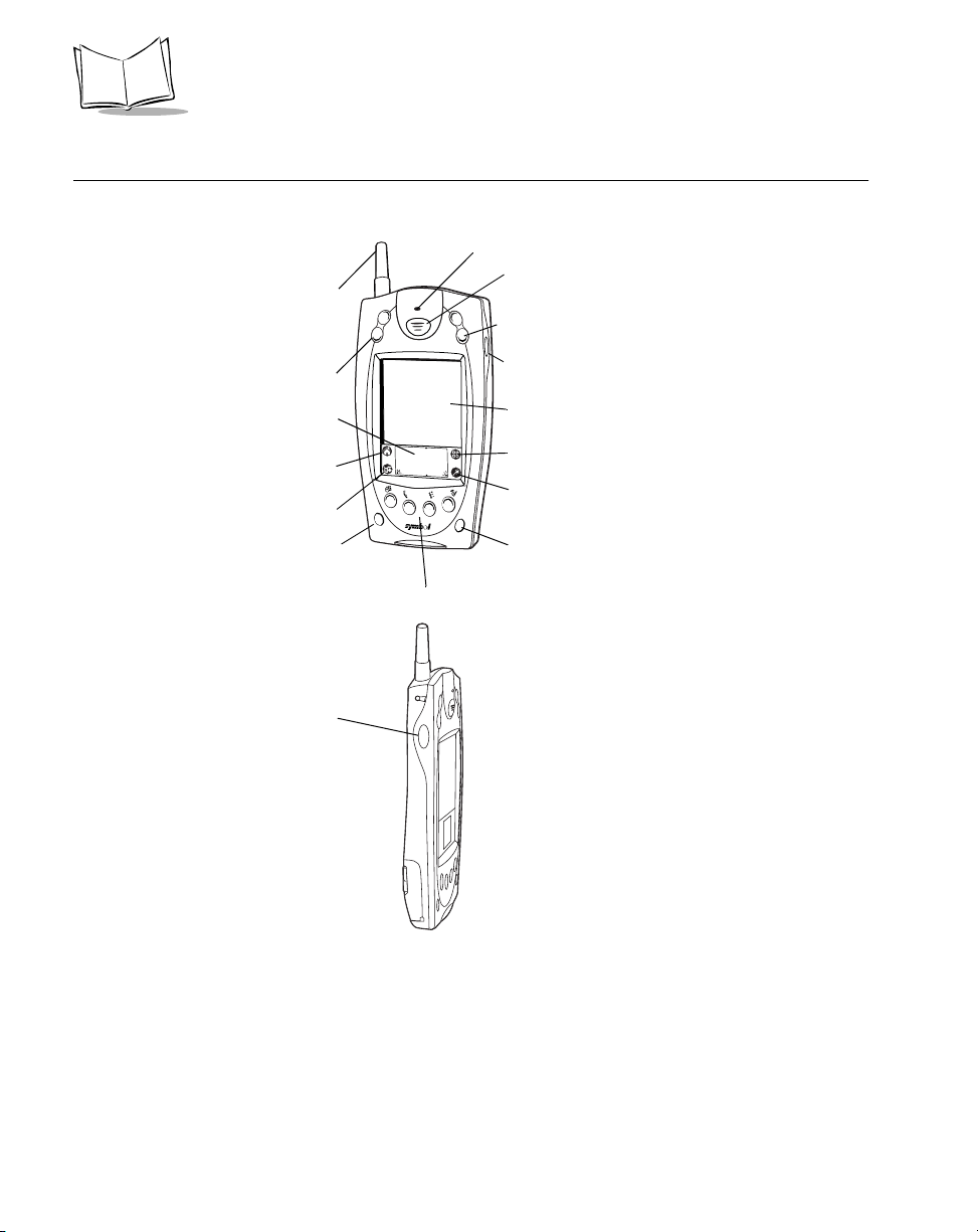
Parts of the SPT 1700
Front View
Left View
WAN Antenna
(SPT 1733/34 only)
Scroll But t on
(Up and Down)
Graffiti Input Area
Applications Icon
Menu Icon
Power Button
Left Scan
Trigger
Laser Decode LED
Center Scan Button
Scroll But t on
(Up and Down)
Right Scan Trigger
LCD (Screen)
Calculator Icon
Find Icon
Contrast Button
Application Buttons
1-4
Page 29
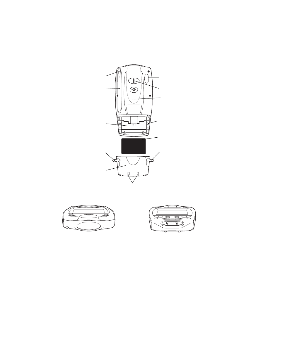
Back View
Getting Started with the SPT 1700
Stylus
Stylus Silo
Battery
Compartment
Battery Latch
Battery C over
Top View
Infrared Port
Handstrap Connector
Speaker
Reset Button
Lithium-Ion Battery
Battery Latch
Handstrap Connector
Bottom View
Serial PortScanner Exit Window
1-5
Page 30

SPT 1700 Series Product Reference Guide
Getting Started with the SPT 1700
Before you can use your SPT 1700, perform the basic set up procedures covered on the
following pages. Specifically:
• Set up the cradle (optional)
• Install and charge the battery
• Start the SPT 1700
• Initiate a Spectrum24 network (SPT 174x only) or wide area network (WAN)
connection (SPT 173X only).
Setting Up the Cradle
There are optional cable and cradle solutions that enable you to charge the terminal’s
battery and synchronize information on your SPT 1700 terminal with host system
applications.
There are several cable and cradle options available for the SPT 1700:
• Synchronization/Char gi ng Cabl e
• CRD1700-1000S Single-slot Serial Cradle
• CRD1700-4000S Four-slot Serial Cradle
• CRD1700-1000M Single-slot Modem Cradle
• CRD1700-4000E Four-slot Ethernet Cradle.
This section describes the procedures for connecting each of these cradles to the host PC.
Using the Synchronization/Charging Cable
To charge the termi nal ’s battery using the Synchronization/Charging Cable:
1. Make sure the battery is installed in the terminal. Refer to
page 1-13 for instructions.
1-6
Installing the Battery
on
Page 31

Getting Started with the SPT 1700
2. Insert the cable into the bottom of the terminal, as shown.
Synchronization/
Charging Cable
3. Plug the power cable into a wall outlet and plug the other end into the battery
charging receptacle on the side of the Synchronization/Charging Cable.
Battery Charging
Receptacle
Power Supply
Serial Cable
The battery is fully charged after approximately two hours.
To perform serial host communication using the cable, plug the other end of the cable into
an available communication port on the back of the host computer.
1-7
Page 32

SPT 1700 Series Product Reference Guide
CRD1700-1000S Single-slot Serial Cradle
To connect the cradle:
1. Turn off your computer.
2. Plug one end of the serial cable into the host connector on the back of the cradle.
3. Plug the other end of the serial cable into the serial communication port on your
computer.
You may require a 9-pin to 25-pin adapter, p/n 160-0072 to connect
Note:
the cable to the serial port on the back of your computer.
Your SPT 1700 terminal requires a dedicated port. It cannot share a
Note:
port with an internal modem or other device. If you are unsure about
the location of the serial port on your computer, refer to the user’s
manual supplied with the computer.
4. Connect the power jack to the power receptacle on the back of the cradle.
5. Plug the power cable into the wall.
CRD1700-4000S Four-slot Serial Cradle
To connect the cradle:
1. Turn off your computer.
2. Plug one end of the serial cable into the host connector on the back of the cradle.
3. Plug the other end of the serial cable into the serial communication port on your
computer.
1-8
Page 33

Getting Started with the SPT 1700
Note:
You may require a 9-pin to 25-pin adapter, p/n 160-0072 to connect
the cable to the serial port on the back of your computer.
Note:
Your SPT 1700 terminal requires a dedicated port. It cannot share a
port with an internal modem or other device. If you are unsure about
the location of the serial port on your computer, refer to the user’s
manual supplied with the computer.
4. Connect the power jack into the power receptacle on the back of the cradle.
5. Plug the power cable into the wall.
CRD1700-1000M Modem Cradle
To connect the cradle:
1. Turn off your computer.
2. Plug the RJ-41 connector of the communication cable into the Line Out port on the
back of the cradle.
3. Plug the other end of the cable into the serial port on the back of your computer.
4. Plug one end of the phone cord into the Line In port on the cradle, and the other
end into a wall phone jack.
5. Connect one end of the power cable into the power port on the back of the cradle,
and plug the other end into a wall outlet.
1-9
Page 34

SPT 1700 Series Product Reference Guide
Note:
Your SPT 1700 terminal requires a dedicated port. It cannot share a
port with an internal modem or other device. If you are unsure about
the location of the serial port on your computer, refer to the user’s
manual supplied with the computer.
Refer to
Chapter 9, Applications: HotSyn c®
for instructions on configuring the cradle and
terminal for modem synchronization.
CRD1700-4000E Ethernet Cradle
Before setting up the cradle, make sure that Symbol Palm Terminal Desktop Software (p/n
SW-35138-xx) is installed and running on the host computer, as well as properly configured
Network HotSync software on the SPT 1700 terminal. Refer to the section
T erminal Desktop Softw are
on page 1-23 for instructions on installing this software. Specific
software setup necessary to use the CRD1700-4000E is discussed in Chapter 9,
Applications: HotSync®
.
A DHCP server must be configured and operational on the subnet to which the cradle will
be attached.
To connect the cradle:
1. Connect the power supply cable round plug to the power connector on the back of
the cradle.
2. Connect the power supply AC plug to a standard electrical outlet.
Note:
International customers must use a separate AC power cable
appropriate for their respective country.
Symbol Palm
DC Power
Connector
The cradle’s LEDs blink, then remain off until a terminal is inserted into one or more of the
slots.
1-10
Page 35

Getting Started with the SPT 1700
To set up for network communications:
1. Ensure there is a DHCP server accessible to the CRD1700-4000E on the subnet
to which it will be attached.
2. Connect one end of a standard 10 Base-T network cable to the middle connector
on the back of the CRD1700-4000E. Connect the other end of the cable to a hub
which is connected to your subnet.
3. Power-up the unit; the CRD1700-4000E performs its power-up sequence, then
attempts to collect all network parameters from the local DHCP server.
If configuration of the unit from the local DHCP server fails, all LEDs flash red. The unit
becomes unresponsive until power is removed, the unit is connected to a network with a
DHCP server, and power is restored.
Note:
Before communication between the SPT 1700 terminal and the host
computer can take place, the Symbol Palm Terminal Desktop
Software must be installed and running on the host computer.
VCD 1700 Series Vehicle Cradle
The SPT 1700 provides a serial port at the bottom of the terminal. When you insert a
terminal into a VCD 1700 cradle, it connects to the cradle’s serial port. The terminal can
then use the cradle’s serial port to communicate with an external device.
To connect the cradle:
1. Plug a 9-pin serial cable into the serial port located next to the power port at the
bottom of the cradle. Note that some devices may require the serial cable to be a
null modem cable.
1-11
Page 36

SPT 1700 Series Product Reference Guide
Power Input Cable
To Ve h i c le
Power Source
To External Device
Note:
The external device must use an RS-232 serial connection limited to
Serial Cable
TXD, RXD, RTS and CTS data lines. It must also have its own power
supply, as the cradle’s serial port does not provide power.
2. Connect the other end of the cable to the serial port of the external device (
host computer, printer, or modem).
To begin communication:
1. Insert the terminal into the cradle.
2. Connect the Power Input cable to your vehicle power source. Then plug the cable
into the Power Port on the terminal.
3. To initiate communication, make appropriate selections on the terminal, as
determined by the application you are using.
Note:
Removing a terminal during data communication will disrupt
communication between the terminal and the attached device.
e.g.
, a
1-12
Page 37

Getting Started with the SPT 1700
Installing the Battery
To install the battery in your SPT 1700:
1. Open the latches on the battery cover and lift it away from the SPT 1700.
Latch
Latch
2. Insert the lithium-ion battery in the battery compartment, making sure it snaps into
place.
3. Replace the battery cover and re-secure the latches.
Note:
Be careful to position the battery latches completely open while
securing the battery cover on the terminal.
1-13
Page 38

SPT 1700 Series Product Reference Guide
Charging the Battery
Before using your SPT 1700 for the first time, charge the lithium-ion battery. The terminal’s
battery can be charged using the Cradle, the Synchronization/Charging Cable, or the
Universal Battery Charger (UBC). For instructions on using the UBC to charge your
batteries, refer to the Quick Reference Guide which came with your UBC. Follow these
same procedures to recharge the battery when the terminal’s battery level is low.
Using the Cradle to Charge the Battery
To charge the termi nal ’s battery using the CRD 1700 cradle:
1. Make sure the battery is installed in the terminal. Refer to
page 1-13 for instructions.
2. Make sure the cradle is plugged into a wall outlet.
3. Insert the SPT 1700 terminal in the cradle as shown:
Battery
Charging
LED
On the CRD1700-1000S, the battery charging LED turns red to indicate that the battery is
charging, then turns green after approximately two hours to indicate that the terminal’s
battery is fully charged.
Installing the Battery
on
Spare Battery Charging
The CRD1700-1000S single-slot cradle has a spare battery charging slot which charges
the terminal’s spare battery . Insert the battery in the spare battery charging slot in the back
of the cradle. The spare battery charging LED turns red to indicate the spare battery is
1-14
Page 39

Getting Started with the SPT 1700
charging, then turns green after approximately two hours to indicate the battery is fully
charged.
Spare Battery
Charging LED
Attaching the Handstrap
The SPT 1700 has an optional handstrap which increases comfort when holding the
terminal for extended periods of time. To attach the handstrap to the back of the terminal:
1. Thread the metal piece through the metal handstrap connection on the back of the
terminal.
1-15
Page 40

SPT 1700 Series Product Reference Guide
2. Slide the flat metal piece into the handstrap connection on the bottom of the
terminal.
Thread metal piece
through this connector
Slide flat metal piece
up and into this
connector
®
3. Adjust the velcro
strap to fit your hand.
Starting the SPT 1700
After charging and installing the battery, start the terminal by pressing the red power button
on the front of the unit. If the terminal does not power on, perform a hard reset.
Note:
When starting the terminal for the first time, or whenever the battery
is completely drained, a hard reset is required.
To hard-res et the termi nal :
1. Remove the battery cover from the back of the terminal.
2. Hold down the power button on the front of the SPT 1700 terminal.
3. While holding down the power button, use the tip of the stylus to gently press the
reset button on the back of the terminal.
4. Release the reset button.
5. Release the power button.
1-16
Page 41

Getting Started with the SPT 1700
6. When a message displays on the screen warning that you are about to erase all
the data stored on your SPT 1700 terminal, do one of the following:
a. Press the upper half of either of the scroll buttons on the front panel of the SPT
1700 terminal to complete the hard reset and display the Digitizer screen.
b. Press any other button to perform a soft reset.
Note:
With a hard reset, the current date and time are retained. Formats
Preferences and other settings are restored to their factory default
settings.
After initial start up, always start the terminal by pressing the red power button.
Calibrating the Screen
The first time you start your SPT 1700 (or after a hard reset), the calibration screen
displays. Follow the steps in this section to align the internal circuitry of your SPT 1700 with
its touch-sensitive screen.
Note:
If your SPT 1700 unit came pre-loaded with a custom software
application, you may not need to calibrate your screen, in which
case you will not see the calibration screen.
To calibrate your SPT 1700 for first time use:
1. Press the power button on the front panel of your SPT 1700 to display the
calibration screen. (This screen also displays following a hard reset).
Power
Button
2. Remove the stylus from its storage silo on the back of the SPT 1700.
1-17
Page 42

SPT 1700 Series Product Reference Guide
3. Tap the exact center of each target that displays on the screen with the tip of the
stylus.
If you need to recalibrate the screen at any time, open the Prefs application, tap on the pulldown menu at the top right corner of the screen, and select the digitizer option.
Setting the Time
The General Preferences screen is the first screen to display after you align the digitizer on
your SPT 1700 terminal.
If the General Preferences screen is not on your SPT 1700 terminal
Note:
screen, you may have pressed one of the application buttons on the
front panel. Refer to General Preferences on page 14-10 for
information on displaying the General Preferences screen.
1-18
Page 43

Getting Started with the SPT 1700
To set the current time:
1. Tap the Set Time box in the General Preferences screen to open the Set Time
screen.
Tap here
2. Tap the up or down arrows to change the hour.
3. Tap the minutes box, and then tap the arrows to adjust the settings for the current
time.
4. Tap the AM or PM box to select the time of day.
Note:
Your SPT 1700 terminal can also display time based on a 24-hour
clock. Refer to Formats Preferences on page 14-9.
5. Tap the OK button to close the Set Time screen and return to the General
Preferences screen.
Setting the Current Date
The Set Date box in the General Preferences screen is used to set the current date for your
SPT 1700 terminal.
To set the current date:
1. Tap the Set Date box to open the Set Date screen.
2. Tap the arrows at the top to select the current year.
1-19
Page 44

SPT 1700 Series Product Reference Guide
Tap arrows to select year
Tap to select month
Tap to select d a te
3. Tap a month box to select the current month.
4. Tap the current date to close the Set Date screen and return to the General
Preferences screen.
Note:
You do not need to adjust the other General Preference settings at
this time. Refer to General Preferences on page 14-10 for
information about the remaining options.
Configuring the Spectrum24 Network (SPT 174x only)
Before the SPT 174x can be used on the Spectrum24 wireless LAN, your facility must be
set up with the equipment required to run the wireless LAN and your terminal must be
properly configured. Refer to Chapter 2,
terminal for use with Spectrum24.
Network Setup
for instructions on configuring your
Configuring the Wide Area Network (SPT 173x only)
Before the SPT 173X can be used on a WAN (CDPD or GSM), your terminal must be
properly configured. Refer to Chapter 2,
terminal for use with a WAN.
1-20
Network Setup
for instructions on configuring your
Page 45
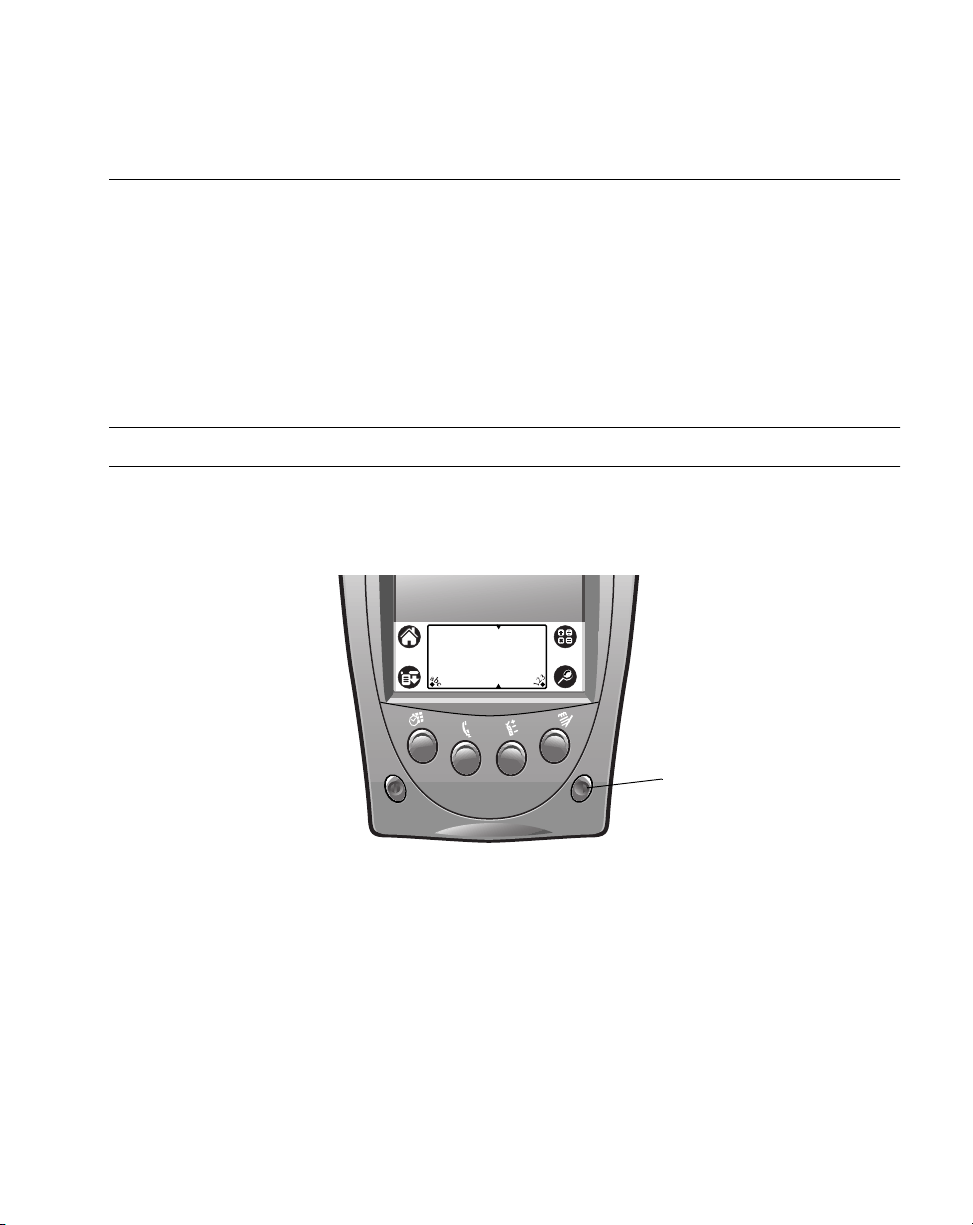
Getting Started with the SPT 1700
Using the SPT 1700
This section describes the procedures for the basic use of the SPT 1700 series terminal.
Topics covered include powering on the terminal, using the backlight, adjusting the screen
contrast, writing with the stylus, and using the onscreen keyboard.
Using the Power Button/Backlight Control
The power button turns the SPT 1700 on and off. This button also serves as your backlight
control for low-light conditions. With the unit on, press and hold the power button for
approximately 2 seconds to turn the backlight on and off.
Note:
When the backlight is on, the screen text displays in reverse video.
Using the Contrast Control
The contrast control button is located on the lower right-hand side of the terminal.
Contrast
Control
To adjust the contrast:
1. Press the contrast control button, which displays the contrast adjusting bar on the
terminal’s screen.
2. Using your stylus, adjust the contrast by scrolling the contrast bar until the contrast
is set to the desired level, or use either of the scroll buttons on the top of the
terminal to adjust the contrast level.
3. Press the contrast control button or tap
contrast control.
on the terminal screen to turn off the
Done
1-21
Page 46

SPT 1700 Series Product Reference Guide
Writing with the Stylus
Your SPT 1700 includes Graffiti® handwriting software as the primary system for entering
text and numbers. Graffiti is a system where simple strokes you write with the stylus are
instantly recognized as letters or numbers. Refer to
Writing Graffiti with the Stylus
on page
3-6 for more information.
Using the Onscreen Keyboard
You can activate the on-screen keyboard any time you need to enter text or numbers on
your SPT 1700. Note that you cannot enter Graffiti characters while using the on-screen
keyboard.
To use the on-screen keyboard:
1. Open any SPT 1700 application.
2. Tap any record name, or tap the
3. Tap the left target to open the Alpha keyboard, or tap the right target to open the
Numeric keyboard.
button with the tip of the stylus.
New
Refer to
1-22
Tap here for letters
keyboard
Using the On-Screen Keyboard
Tap here for numbers
keyboard
on page 3-17 for additional information.
Page 47

Icon Descriptions
Getting Started with the SPT 1700
Applications Icon
Calculator Icon
Menu Icon
Find Icon
Tap to exit the current application and to display a list of available
applications for selection.
Tap to display the calculator application.
Tap from within an application to display the menu of options for the
selected application.
Tap from within an application to enter search criteri a to find an entry.
Symbol Palm Terminal Desktop Software
Symbol Palm Terminal Desktop software extends many of the functions of your SPT 1700
Series terminal to your computer. Although using Symbol Palm Terminal Desktop software
is optional, when you use it with your SPT 1700 Series terminal and the built-in HotSync
technology, you can fully synchronize the information on your SPT 1700 Series terminal
with the information on your computer. Changes you make on your SPT 1700 Series
terminal or Symbol Palm Terminal Desktop display in both places after you synchronize.
With Symbol Palm Terminal Desktop software you can:
• Work with your SPT 1700 terminal applications on your computer. The Symbol
Palm Terminal Desktop software duplicates the Date Book, Address Book, To Do
List and Memo Pad applications on your SPT 1700 terminal, so you can view, enter
and modify any data stored on your SPT 1700 terminal.
• Back up the data stored on your SPT 1700 terminal with HotSync technology and
synchronize the data with the Symbol Palm Terminal Desktop software.
Synchronization is a one-step procedure that ensures your data is always safe and
up-to-date. Refer to Chapter 9,
Applicatio ns: HotSync ®
for information about using
this feature.
• Import and export data, so you can easily transfer data from other Windows
applications into Address Book or Memo Pad.
• Print your Date Book, Address Book, T o Do List and Memo Pad information on any
Windows-compatible printer.
1-23
Page 48

SPT 1700 Series Product Reference Guide
System Requirements
To install and operate the Symbol Palm Terminal Desktop software, your computer system
must meet the following requirements:
• Windows 95 or Windows NT 4.0
• IBM-compatible 486 computer or higher
• 8 MB RAM (memory)
• 12 MB available hard disk space
• VGA monitor or better
• CD-ROM drive
• Mouse
• One available serial port.
minimum,
16 MB recommended
Optional Equipment
• Modem
• Windows-compatible printer.
Symbol Palm T erminal Desktop Software Installation
The following instructions guide you through installing the Symbol Palm Terminal Desktop
software. After you install the software, refer to the Help menu for complete information
about how to use the Symbol Palm Terminal Desktop software.
To ensure a safe and uninterrupted installation of the Symbol Palm Terminal Desktop
software, do the following before installing:
• Connect the cradle to your computer.
• If you have placed your SPT 1700 terminal in the cradle, remove it during software
installation.
• Exit all programs, including those that run automatically at startup, such as fax
software, virus protection software, screen-saver software, and application
toolbars such as Microsoft
• Do
1-24
simply copy the Symbol Palm T erminal Desktop files to your hard drive. You
not
must use th e installer to place the files in their proper locations and then
decompress them.
®
Office.
Page 49

Getting Started with the SPT 1700
To install the Symbol Palm Terminal Desktop software:
1. Insert the Symbol Palm Terminal Desktop Software CD into the CD-ROM drive on
the PC.
2. If your CD-ROM supports the auto-run feature, an installation menu automatically
displays on your desktop. If not, navigate to your CD-ROM drive and double-click
on setup.exe. The Welcome Screen displays.
3. Follow the directions as the installation program guides you through the install
process.
1-25
Page 50

SPT 1700 Series Product Reference Guide
1-26
Page 51

Chapter 2
Network Setup
Chapter Contents
Introduction . . . . . . . . . . . . . . . . . . . . . . . . . . . . . . . . . . . . . . . . . . . . . . . . . . . . . . . . . . . . . . . . . . 2-3
Configuring a Spectrum24 Connection (SPT 174x Only) . . . . . . . . . . . . . . . . . . . . . . . . . . . . . . . 2-3
Configuring a CDPD WAN Connection (SPT 1733 Only) . . . . . . . . . . . . . . . . . . . . . . . . . . . . . . . 2-8
Setup Wizard . . . . . . . . . . . . . . . . . . . . . . . . . . . . . . . . . . . . . . . . . . . . . . . . . . . . . . . . . . . . . 2-8
Maintenance Screens and Menus . . . . . . . . . . . . . . . . . . . . . . . . . . . . . . . . . . . . . . . . . . . . 2-13
Merlin Menu Options . . . . . . . . . . . . . . . . . . . . . . . . . . . . . . . . . . . . . . . . . . . . . . . . . . . . . . . . . . 2-15
Merlin Menu . . . . . . . . . . . . . . . . . . . . . . . . . . . . . . . . . . . . . . . . . . . . . . . . . . . . . . . . . . . . . 2-15
Advanced Menu . . . . . . . . . . . . . . . . . . . . . . . . . . . . . . . . . . . . . . . . . . . . . . . . . . . . . . . . . . 2-16
Help Menu . . . . . . . . . . . . . . . . . . . . . . . . . . . . . . . . . . . . . . . . . . . . . . . . . . . . . . . . . . . . . . 2-24
Configuring a GSM WAN Connection (SPT 1734 Only) . . . . . . . . . . . . . . . . . . . . . . . . . . . . . . . 2-25
2-1
Page 52

SPT 1700 Series Product Reference Guide
2-2
Page 53
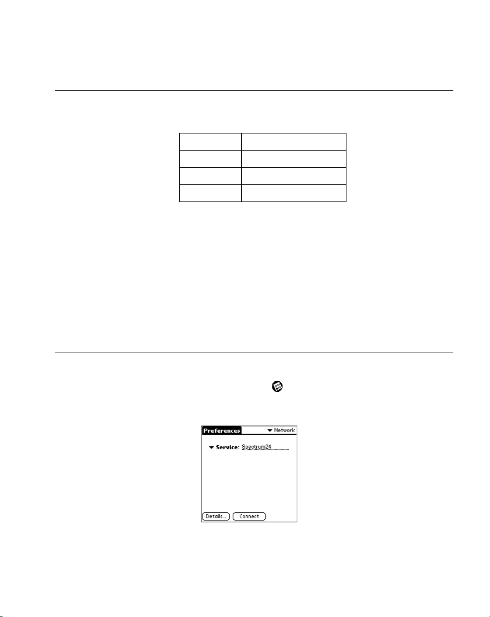
Network Setup
Introduction
Wireless networks allow SPT 1700 series terminals to communicate wirelessly, and to send
captured data “real time” to a host device. Terminals and their supported network types are:
T ermi n al Network Te chn olog y
SPT 174x
SPT 1733
SPT 1734
Before a terminal can be used on a Spectrum24 LAN, your facility must be set up with the
equipment required to run the network and the terminal must be properly configured. Before
a terminal can be used on a CDPD/GSM WAN, you must activiate your device on the
network. Refer to the following sections for specific configuration information for each
terminal type:
CDPD WAN Connection (SPT 1733 Only)
1734 Only)
Configuring a Spectrum24 Connection (SPT 174x Only), Configuring a
.
Spectrum 24 (LAN)
CDPD (WAN)
GSM (WAN)
, and
Configuring a GSM WAN Connection (SPT
Configuring a Spectrum24 Connection (SPT 174x Only)
To configure your SPT 174x terminal for use on a Spectrum24 network:
1. On the Main Application screen, tap the icon.
2. Tap the preference options pick list and select Network. The Network Preference
screen displays:
2-3
Page 54

SPT 1700 Series Product Reference Guide
Note:
Refer to Network Preferences Menu Commands on page 14-27 for
details about using the Network Preferences menu options.
3. T ap the Service pick list and select Spectrum24, then tap Details. The Spectrum24
Preferences screen displays:
Enter the following information:
4. Extended Service Set ID (ESS ID).
The ESS ID identifies the radio network and differentiates between different radio
networks. All terminals on the same network, as well as the access points in your
facility, must have the same ESS ID. Ask your System Administrator for the correct
ESS ID number of your network.
5. Internet Protocol address (IP).
Each SPT 174x terminal requires a unique internet address (IP address). This
address can be administered and entered manually through the terminal, or
administered and allocated by a server on the network, using DHCP.
Note:
The default value for this field is Use DHCP. Use this option if you
want the IP address to be dynamically selected by the DHCP server.
2-4
Page 55

Network Setup
a. To manually enter the IP address information for this terminal, deselect Use
DHCP and tap Settings. The IP Settings screen displays:
b. Enter the IP address, Subnet mask, and Gateway address for this terminal.
Tap each field to display a keypad for selection of the address information. Each
part of the four-part address must be in the range of 0-255; numbers are the only
allowable characters in these fields. Ask your Internet Service Provider or your
System Administrator for the correct IP, Subnet and Gateway information.
c. Tap
to exit the Keypad.
Done
d. Tap OK to save the information and return to the Spectrum24 Preferences
screen.
6. To enable DNS, tap the Enable DNS box. A Details button is added to the screen.
Note:
Many systems do not require a DNS. If you are not sure, leave the
DNS fields blank.
a. Tap Details to display the Details screen.
Enter the Host and Domain Names. If you need more space to enter name
information, tap the arrow to the right of these fields to display a blank screen.
2-5
Page 56

SPT 1700 Series Product Reference Guide
Tap the Primary and Secondary DNS fields to display a keypad to enter the
address information for these fields. Each part of the four-part address must be in
the range of 0-255; numbers are the only allowable characters in these fields. Ask
your Internet Service Provider or System Administrator for the correct Primary or
Secondary DNS numbers.
b. Tap OK to save the information and return to the Spectrum24 Preferences
Screen, or Cancel to return to this screen without saving the DNS information.
7. Tap the
Note:
This button is available for the SPT 1746 only.
Radio Config
button to set the radio configuration parameters.
a. The following parameters display:
PwrMode The power-saving level of the terminal.
Diversity Determines whether the radio firmware
2-6
“5” uses the least power and is the
recommended configuration.
attempts to use one or two antenna
ports for communications. It is
important to match this setting with the
actual number of anten nas in use.
If set to “Both”, the radio firmware
attempts to use both antenna ports for
communications.
is the default and provides the
Both
best chance of a clear signal.
Page 57

Channel The specific Direct-Sequence Channel
used for communications between the
AP (Access Point) and the MU (Mobile
Unit). Channels are unique per country .
Preamble Approximately 8 bytes of the packet
header generated by the AP and is
attached to the packet prior to
transmission. Preamble length is
transmission data rate dependent. The
short preamble is 50% shorter than
long preamble.
Both the MU and AP need to be set to
the same preamble to associate.
Encryption Tap to enable encryption, an efficient
method of preventing data theft and
improving data security.
Key Index The specific algorithm used for each
encryption key.
Encrypt Len Encryption length.
Choose either 40 bit or 128 bit.
40-bit encryption: Requires a 10 Hex
digit Encryption key.
128-bit encryption: Requires an access
code. Contact the Symbol
Technologies Support Center
(1-800-653-5350) for details.
Network Setup
Keys 1 - 4 Specific key codes required for
encryption.
Note:Symbol Technologies recommends using the default settings, as
they have been set to maximize the performance of the SPT 1746.
8. Tap
when configuration is complete, then tap OK to return to the Spectrum24
Done
Preferences screen.
9. Tap
Connect
to connect to the network.
2-7
Page 58

SPT 1700 Series Product Reference Guide
Configuring a CDPD WAN Connection (SPT 1733 Only)
Before the SPT 1733 terminal can be used, you need to be activated on a CDPD network.
All CDPD identification and address information is entered through the Preferences
application on the SPT 1733 terminal.
To configure your SPT 1733 terminal for use on a CDPD network, tap the icon from the
Applications Launcher. The main Merlin screen displays:
Setup Wizard
The first time that the MerlinTM Modem Manager software is started the Setup Wizard will
display and prompt you through the steps to configure and set up the terminal for operation.
2-8
Page 59

Network Setup
Note:
If this is not the first time you are accessing the Merlin Modem
Manager, Tap the icon and select Setup Wizard from the Merlin
menu.
At any time, you can choose to cancel the Setup Wizard and exit back to the Application
Launcher by tapping the
Cancel
button. If you do choose to cancel, the Setup Wizard will
be displayed the next time that the Modem Manager is selected. It is recommended that
once you begin the setup process you continue through to its completion.
1. To begin configuration, tap
. The Network Provider screen displays:
Next
2. Select a Wireless Provider from the pick list:
2-9
Page 60

SPT 1700 Series Product Reference Guide
3. Tap Other if you need to enter a Service Provider Interface number representing a
different carrier. The following screen displays:
4. Enter the SPI number and tap
5. The Network Provider screen reappears. Tap
Note:
The Setup Wizard will not proceed until a CDPD carrier selection
Done
.
to continue.
Next
has been made.
6. The Configure Palm Device screen displays:
7. Tap the
Configure Preferences
button to configure the terminal with the network
library settings that Symbol recommends. A “Palm Configuration Complete”
message will display below the
Configure Preferences
button when the process is
finished.
2-10
Note:
If you are confident that the Network Preferences are correct, you
may bypass this step. However, it strongly suggested that you verify
preference configuration.
Page 61

Network Setup
8. Tap
to continue. The Contact A Provider screen displays:
Next
You are informed that you will need an IP address and two DNS addresses from
your Network Provider before continuing. Tap
to continue.
Next
9. The Settings screen display s:
10. Enter the required information and tap
to continue. You are prompted to
Next
confirm the settings. Verify the information you entered is accurate and tap
Next
2-11
.
Page 62

SPT 1700 Series Product Reference Guide
11. Once the modem has been configured, the Auto Config screen displays:
Tap to attempt
connection with the
network now
i
T ap if you are going to
wait for your account
to be registered
Tapping either button displays the Check Network screen as the modem attempts
to register.
12. When the modem connects successfully and the following screen displays:
2-12
Page 63

Network Setup
Maintenance Screens and Menus
The SPT 1733 terminal includes menu commands to make it fast and easy to configure and
check the status of your modem. This section explains the menu commands specific to the
Merlin Modem Manager.
Quick Status Screen
The initial Merlin Modem Manager screen displays numerous modem parameters. These
include the detection of a CDPD channel and whether the modem has successfully
registered. The modem's status is updated every 3 seconds.
Setting Description
Cellular Signal
Present
CDPD Service
Detected
Modem Ready
Registered
RSSI
Error Detect
System Busy
When checked, it indicates that the modem has identified a
cellular signal.
When checked, it indicates that the modem has identified and
is synchronized to a CDPD signal in the area.
When checked, it indicates that the modem has successfully
registered with a CDPD service provider in the coverage area.
When the indicator is lit a working data connection exists and
can be used by other applications to tran sm it and re ce iv e
data. Until this checkbox is selected, the modem can neither
transmit nor receive data.
Measures Received Signal Strength from the wireless base
station. These values range from one to ten bars. The greater
the number of bars, the better the performance of the modem.
When checked, it indicates that a large number of errors have
been detected by the modem. Under these circumstances the
modem may continue to operate but with a severely reduced
performance, caused by the increased likelihood of
connection retries and data errors when communicating with
the wireless base station.
When checked, it indicates that the currently detected CDPD
system is busy. The modem may continue to operate but at a
decreased level of performance.
Wireless Provider
Displays the CDPD channel’s System Provider’s Identifier.
2-13
Page 64

SPT 1700 Series Product Reference Guide
Setting Description
RF Channel Shows the CDPD channel that is currently active. If the unit is
not registered or is searching for a channel, the value
displayed will be either "Searching A" or "Searching B”,
depending on the state of the modem. Once a channel has
been detected, a numeric value for the channel is displayed.
Registration Error This shows either "None" or a numeric value between 1 and
7. If "None" is displayed there was a successful registration
without any errors. If a numeric error code is displayed then an
error has occurred. Tap to display details about the error.
Shutdown Turns the modem off.
2-14
Page 65

Network Setup
Merlin Menu Options
Tapping the Menu key provides a series of menus. Merlin Modem Manager software
supports shortcuts to access any of the menus. The following are the available menu
options.
Merlin Menu
Disconnect
Shutdown
Reconnect
Network
Prefs
Setup
Wizard
Terminates the active Network session with the modem. If
disconnected, the Merlin Modem Manager can no longer perform
3-second updates.
Performs the same function as Disconnect.
T erminates the active Network session with the modem and forces
the modem to power off. If the modem is shutdown, the Merlin
Modem Manager can no longer perform 3-second updates.
Reconnects a network session that has previously been
disconnected. When
updates of the software begin again.
Brings the user directly to the Network Preferences screen. Refer
to Chapter 14,
Launches the Setup Wizard to configure your modem.
Reconnect
Applications: Preferences
is selected, the 3-second
for details.
2-15
Page 66

SPT 1700 Series Product Reference Guide
Advanced Menu
Config (Configuration)
Status
Terminal
Ping
Configuration Screen
Displays the network connection configuration screen,
allowing you to make the desired changes or refinements
to your network settings. Refer to
on page 2-16 for detailed information.
Displays the Detailed Status screen, which shows
various details about how your modem is connecting to a
Network or the Internet. This screen is used for diagnostic
purposes and for assisting customer service in
diagnosing any problems you may encounter with
Network connections. Refer to
20 for detailed information.
Displays the terminal emulator, allowing you to connect to
and send AT commands to the modem. Refer to
Screen
Displays the Ping screen, allowing to send a packet to a
particular IP address to determine if it is online. Refer to
Ping Screen
on page 2-22 for detailed information.
on page 2-23 for detailed information.
Configuration Screen
Status Screen
on page 2-
Terminal
2-16
Page 67

Network Setup
You can select any of the buttons, or triggers, and modify their settings. Note that none of
your changes will become active until you tap the
button. When
Save
is selected, you
Save
are provided with the Disconnecting and Reconnecting screens, indicating that the settings
are being saved and the modem is being reset with the new settings. The
Save
button also
returns you to the Quick Status screen.
IP Address This is the current IP address of the modem. Tap to enter
a new IP address.
Primary DNS This is the current Primary DNS address of the modem.
Tap to enter a new DNS address.
Secondary DNS This is the current Secondary DNS address of the modem.
Tap to enter a new DNS address.
Sleep Mode Allows or disallows the modem to enter the low-power
mode. Please note that this feature is only functional when
used on Wireless IP networks that support it.
Network Provider Configure the side preferen ce s for the modem. Al l CDPD
systems are cate go rize d in to " A" sy stem s or "B " sy st ems .
This setting determines which system category
(categories) how the modem will search for a CDPD
system among the t wo s yst em c at eg ory choi ce s. R e fer t o
Network Provider pick list
on page 2-18 for detailed
information.
SPI, SPNI, WASI Configures all identification values for a particular system
or Wireless IP network. Also called Service ID parameters.
Service ID Pref Configures the preferences for the service ID parameters.
Refer to
Network Provider pick list
on page 2-18 for
detailed information.
Channel Hot List Configures a list of channels upon which the modem will
attempt to find service. This user-configurable list can
contain up to 32 channels, listed in the particular order that
you want the modem to use.
Hot List Operation Configures how the Channel Hot List entered is used.
2-17
Page 68

SPT 1700 Series Product Reference Guide
Sleep Mode pick list
Enabled The modem will attempt to enter a low-power mode if it is not required to
carry out any communications with a Network. The modem may respond
sluggishly to the first communication request when it is required again.
Disabled The modem is not allowed to enter sleep mode.
Network Provider pick list
A only The modem will search for a CDPD system on the "A" side only . For users
who do not roam, this selection can sometimes speed the registration
process, as the modem does not have to look on the "B" side as well
before it can register.
B only Same as "A only" except on the "B" side.
Prefer A The modem will search for a CDPD system on the "A" side first and
attempt registration on any system it finds. However, if the modem cannot
register on the "A" side, it will then attempt to find service on the "B" side.
For users who roam, this setting would be appropriate if the home system
was on the "A" side.
Prefer B The modem will search for a CDPD system on the "B" side first and
attempt registration on any system it finds. However, if the modem cannot
register on the "B" side, it will then attempt to find service on the "A" side.
For users who roam, this setting would be appropriate if the home system
was on the "B" side.
2-18
Page 69

Service ID Pref pick list
Network Setup
Only SvcID The modem will attempt to detect
ID parameters for registration. This is useful in cases where the
user wishes to prevent roaming to any other system but his home
one.
PreferSvcId The modem will first attempt to register on the system described
by the SPI/WASI/SPNI entries. If no system is found, the modem
will attempt to register on the remaining available systems in the
area. This is useful in situations where the user spends most of his
time in one area and occasionally roams. In this case, the user
would enter the Network ID parameters that reflect the system he
most often will register on. Another situation where this may be
useful is in cases where the user has two systems in his area but
prefers service on one due to rate advantages, etc.
IgnoreSvcID The modem will attempt to register on any system but that
reflected in the Network ID entries. This is useful in situations
where the user wishes to block registration on systems in his area
that he does not have an agreement with. This may speed up the
registration process in some areas.
Any SvcID The SPI/WASI/SPNI entries are ignored. This is the default
configuration and ensures that the modem will attempt to register
on any valid system that it can find.
the system in the Service
only
Hot List Operation pick list
Scan All Ignores the list of channels and search all of them.
Use List Attempts to search for system on the channels in the list. If service
cannot be found on those channels, the user will be unregistered.
Hybrid Attempts to search for systems on the given channels first, and
then opens the search up to all channels if none can be found.
Given this selection, the modem will also update the channel list
automatically with any channel on which it has found service. In
this way, the channel list is eventually updated with all CDPD
systems in the area.
2-19
Page 70

SPT 1700 Series Product Reference Guide
Status Screen
The Status screen shows modem information which is updated every 3 seconds.This
screen was designed to assist support personnel in diagnosing problems with your modem.
If a problem develops, the Symbol Support Center (Refer to
page -xix for contact information) will find the information displayed here of importance.
There are no menus on this screen and no place for user entry.
Note:
Tapping Done will return you to the Quick Status screen.
Symbol Support Centers
on
CDPD Entry
SEARCH
ACQ'D
2-20
identifies the current CDPD acquisition state.
The modem is searching for service.
The modem has acquired or synchronized to a CDPD system in
the area.
Page 71

Network Setup
RSSI Entry is the signal strength measured on the current channel. During the SEARCH
phase of operation, this value may vary according to the channel on which an attempt will
be made. When ACQ'D, the signal strength measurement should remain somewhat
constant.
Color Area color code being transmitted by the CDPD system.
Chan The current channel. During the SEARCH phase, this value may
change according to the channel that is being attempted. Once a
channel has been ACQ'D, this should remain relatively constant.
CellID CDPD Base Station identifier number.
BLER A measurement of the error rate on the forward channel detected by
the modem.
Side Display of the current Side, given the A/B side distribution of the CDPD
channels.
PL The current Power Level value at which transmission will take place.
SPI The current CDPD Base Station Service Provider Identifier.
WASI The current CDPD Base Station Wide Area Service Identifier.
SPNI The current CDPD Base Station Service Provider Network Identifier.
PwrProd The Power Product value transmitted by the current CDPD system.
RegErr A numeric value representing the last registration error encountered. A
value of 1-7 indicates an error; a value of 0 indicates no error and a
value of 255 indicates no registration attempt was made.
Link Identifies the current CDPD communication link state. Can be Locked
or Searching.
IP is the IP address of the unit.
EID is the Equipment ID of the unit.
2-21
Page 72
SPT 1700 Series Product Reference Guide
Terminal Screen
The Terminal provides an internal terminal emulator for communication with the modem,
allowing users to further customize the operation of their modem based on the AT
command set.
To begin a terminal session:
1. Tap the
Going online terminates any active network session and establishes a serial
session to the modem.
The screen shows the data that is being received from the modem. As data is
received, it is displayed line by line on the screen display. Scroll bars automatically
display when the amount of displayed data exceeds the physical size of the SPT
1733 terminal’s total display area. Y ou c an scroll ba ck and forth t hrough most o f the
previously displayed data. There is a physical limitation on how much previous data
can be scrolled and once this limitation is reached, the oldest data will be
overwritten, so the screen buffer always maintains the last 2000 bytes of data from
the modem.
2. Tap
3. Tap
4. Tap the
At the bottom of the screen is a field for entry of an AT command. There are a number
of pre-defined commands that are included in the Cmd pick list. When you selection of
any of these commands, the modem will automatically send the command, without the
need to press
2-22
Offline
Done
returning you to the Quick Status scree n.
button.
Online
button to close the serial session.
to terminate any serial session and re-establish a network session,
button to clear the current screen buffer.
Clear
button.
Send
Page 73

Network Setup
Ping Screen
From this screen you can send a PING request to another network device whose network
address you already know. This is useful to verify network connectivity.
As with other PING applications, you must enter the IP address of the other network device
in the IP field and then select the desired payload size. Pressing the
the PING. A status line will provide information on whether or not the PING was successful
by displaying a "Success" or "Fail" message. There is a 20 second timeout for a response
before a "Success" or "Fail" message may display.
Please note that there are some limitations on this PING implementation:
button will send
Send
• The size of PING payload is limited to 99 bytes. If a payload of greater than that is
entered, a data error message will be displayed.
• The delay to wait for response is fixed at 20 seconds.
After you have viewed this information, press the OK button to return to the Quick Status
screen.
2-23
Page 74

SPT 1700 Series Product Reference Guide
Help Menu
The Help menu shows basic information about your modem, modem driver, and Merlin
application.
Modem Info Displays the Quick Status screen. Refer to 2-13 for
details.
Driver Info Displays the version of the modem driver.
About Displays version and copyright information for Merlin.
2-24
Page 75

Network Setup
Configuring a GSM WAN Connection (SPT 1734 Only)
To set up a new connection configuration:
1. Tap the icon to open the Applications Launcher.
2. Tap the icon to open the HotSync application.
3. Tap the icon to display the HotSync Options menu and select Connection
Setup.The Connection Preferences screen displays:
4. Tap
5. Enter a name for the connection (i.e., GSM modem) and select GSM Driver to
Modem as the Connection Method.
Refer to
page 9-15 for additional information about this screen.
6. Tap the OK button, followed by the
to create a new configuration. The Edit screen displays:
New
Preparing Your SPT 1700 Terminal for a Modem HotSync Operation
button.
Done
on
2-25
Page 76

SPT 1700 Series Product Reference Guide
2-26
Page 77

Chapter 3
Working with Your SPT 1700
Terminal
Chapter Contents
Introduction . . . . . . . . . . . . . . . . . . . . . . . . . . . . . . . . . . . . . . . . . . . . . . . . . . . . . . . . . . . . . . . . . . 3-3
Applications . . . . . . . . . . . . . . . . . . . . . . . . . . . . . . . . . . . . . . . . . . . . . . . . . . . . . . . . . . . . . . . . . . 3-3
Changing the Applications Launcher Display Format. . . . . . . . . . . . . . . . . . . . . . . . . . . . . . . 3-4
Switching Applications . . . . . . . . . . . . . . . . . . . . . . . . . . . . . . . . . . . . . . . . . . . . . . . . . . . . . . 3-4
Setting Preferences for Applications. . . . . . . . . . . . . . . . . . . . . . . . . . . . . . . . . . . . . . . . . . . . 3-5
Displaying Applications by Category . . . . . . . . . . . . . . . . . . . . . . . . . . . . . . . . . . . . . . . . . . . 3-5
Writing Graffiti with the Stylus . . . . . . . . . . . . . . . . . . . . . . . . . . . . . . . . . . . . . . . . . . . . . . . . . . . . 3-6
Practicing Graffiti with the Memo Pad. . . . . . . . . . . . . . . . . . . . . . . . . . . . . . . . . . . . . . . . . . . 3-6
Writing Letters With Graffiti. . . . . . . . . . . . . . . . . . . . . . . . . . . . . . . . . . . . . . . . . . . . . . . . . . . 3-7
Writing Numbers With Graffiti. . . . . . . . . . . . . . . . . . . . . . . . . . . . . . . . . . . . . . . . . . . . . . . . 3-12
Writing Punctuation Marks With Graffiti . . . . . . . . . . . . . . . . . . . . . . . . . . . . . . . . . . . . . . . . 3-13
Writing Symbols and Extended Characters . . . . . . . . . . . . . . . . . . . . . . . . . . . . . . . . . . . . . 3-14
Writing Accented Characters . . . . . . . . . . . . . . . . . . . . . . . . . . . . . . . . . . . . . . . . . . . . . . . . 3-15
Accent Strokes . . . . . . . . . . . . . . . . . . . . . . . . . . . . . . . . . . . . . . . . . . . . . . . . . . . . . . . . . . . 3-15
Additional Non-English Characters. . . . . . . . . . . . . . . . . . . . . . . . . . . . . . . . . . . . . . . . . . . . 3-15
Navigation Strokes . . . . . . . . . . . . . . . . . . . . . . . . . . . . . . . . . . . . . . . . . . . . . . . . . . . . . . . . 3-15
Graffiti ShortCuts . . . . . . . . . . . . . . . . . . . . . . . . . . . . . . . . . . . . . . . . . . . . . . . . . . . . . . . . . 3-16
Using the On-Screen Keyboard. . . . . . . . . . . . . . . . . . . . . . . . . . . . . . . . . . . . . . . . . . . . . . . . . . 3-17
Using Application Controls. . . . . . . . . . . . . . . . . . . . . . . . . . . . . . . . . . . . . . . . . . . . . . . . . . . . . . 3-19
Using Menus . . . . . . . . . . . . . . . . . . . . . . . . . . . . . . . . . . . . . . . . . . . . . . . . . . . . . . . . . . . . . . . . 3-20
Choosing a Menu . . . . . . . . . . . . . . . . . . . . . . . . . . . . . . . . . . . . . . . . . . . . . . . . . . . . . . . . . 3-20
Graffiti Menu Commands . . . . . . . . . . . . . . . . . . . . . . . . . . . . . . . . . . . . . . . . . . . . . . . . . . . 3-21
Edit Menu Commands . . . . . . . . . . . . . . . . . . . . . . . . . . . . . . . . . . . . . . . . . . . . . . . . . . . . . 3-21
Choosing Fonts . . . . . . . . . . . . . . . . . . . . . . . . . . . . . . . . . . . . . . . . . . . . . . . . . . . . . . . . . . . . . . 3-23
3-1
Page 78

SPT 1700 Series Product Reference Guide
Using Categories. . . . . . . . . . . . . . . . . . . . . . . . . . . . . . . . . . . . . . . . . . . . . . . . . . . . . . . . . . . . . .3-24
Using Categories in Lists. . . . . . . . . . . . . . . . . . . . . . . . . . . . . . . . . . . . . . . . . . . . . . . . . . . .3-25
Defining a New Category. . . . . . . . . . . . . . . . . . . . . . . . . . . . . . . . . . . . . . . . . . . . . . . . . . . .3-26
Renaming Categories . . . . . . . . . . . . . . . . . . . . . . . . . . . . . . . . . . . . . . . . . . . . . . . . . . . . . .3-27
Attaching Notes. . . . . . . . . . . . . . . . . . . . . . . . . . . . . . . . . . . . . . . . . . . . . . . . . . . . . . . . . . . . . . .3-29
Marking Private Entries . . . . . . . . . . . . . . . . . . . . . . . . . . . . . . . . . . . . . . . . . . . . . . . . . . . . .3-30
Beaming Information to Other SPT 1700 Terminals. . . . . . . . . . . . . . . . . . . . . . . . . . . . . . . . . . .3-30
Scanning with the SPT 1700. . . . . . . . . . . . . . . . . . . . . . . . . . . . . . . . . . . . . . . . . . . . . . . . . . . . .3-32
3-2
Page 79

Working with Your SPT 1700 Terminal
Introduction
This chapter explains how to open applications, use the on-screen keyboard, write with the
stylus, perform scanning, and use common features on your SPT 1700 terminal.
Applications
Your SPT 1700 terminal is equipped with a variety of applications which display in the
Applications Launcher. Use the Applications Launcher to open any application installed on
your SPT 1700 terminal. You can also open the four main applications — Date Book,
Address Book, To Do List and Memo Pad — with the buttons on the front panel of your SPT
1700 terminal.
Tip:
The buttons on the front panel provide instant access to the selected
application. You don’t need to turn on your SPT 1700 terminal first.
The Applications Launcher also displays the current time, battery level and application
category.
To open applications:
1. Tap the icon on the SPT 1700 terminal screen to open the Applications
Launcher.
2. T ap the icon of the application that you want to open. If you have many applications
installed on your SPT 1700 terminal, tap the scroll bar to see all of your
applications.
Tip:
As a shortcut, write the Graffiti
first letter of the application you want to use. The Applications Launcher scrolls to
®
handwriting software character stroke for the
3-3
Page 80

SPT 1700 Series Product Reference Guide
the first application that begins with that letter. Refer to
on page 3-12 for additional information.
Graffiti
Writing Capital Letters With
Changing the Applications Launcher Display Format
By default the Applications Launcher displays each application as an icon. As an
alternative, you can choose to show a list of applications.
To change the Applications Launcher display:
1. Tap the icon on the SPT 1700 terminal screen to open the Applications
Launcher.
2. Tap the icon to open the Applications Launcher menus.
3. Tap Preferences from the Options menu to open the Preferences screen.
4. Tap the View By pick list and select the List option.
Note:
Tap the Remember Last Category checkbox to display only the last
category of applications that you have selected.
5. Tap the OK button to close the Preferences screen and display the Applications
Launcher in list format.
Switching Applicat ions
When working in any application, you can tap the icon or press the buttons on the front
panel to switch to any other application. Your SPT 1700 terminal saves your work in the
current application and displays it when you return to the current screen.
3-4
Page 81

Working with Your SPT 1700 Terminal
Setting Preferences for Applications
You can set preferences for individual applications in the Preferences screen. Not all
applications have preference settings.
To set preferences for an application:
1. Open an application.
2. Tap the Menu icon.
3. From the Options menu, select Preferences.
4. Enter the desired preference settings; then tap OK.
Displaying Applications by Category
The category feature enables you to limit the number of applications that display on the
screen. Y ou can assign your applications to categories and then choose to display a single
category or all your applications.
To display applications by category:
1. Tap the icon on the SPT 1700 terminal screen to open the Applications
Launcher.
2. Tap the icon to open the Applications Launcher menus.
3. Tap Category from the App menu to open the Category screen.
4. Tap the pick list next to each application to assign it to a category.
Tip: To create a new category, tap Edit Category from the pick list to open the Edit
Categories screen. Tap the
button to add the category. Tap OK to close the Edit Categories screen.
OK
button, enter the category name, and then tap the
New
3-5
Page 82

SPT 1700 Series Product Reference Guide
5. Tap the
Launcher.
6. Tap the pick list in the upper-right corner of the screen and select the application
category you want to display.
Tip: You can also tap the icon to scroll through the application categories.
button to close the Category screen and return to the Applications
Done
Writing Graffiti with the Stylus
Your SPT 1700 terminal includes Graffiti handwriting software as the primary system for
entering text and numbers. Graffiti is a system where simple strokes you write with the
stylus are instantly recognized as letters or numbers.
This section explains the basics of Graffiti, and how to make strokes in the Graffiti writing
area. Your SPT 1700 terminal also includes Giraffe — a game you can use to practice
writing Graffiti. Refer to
Giraffe.
Installing Games
Practicing Graffiti with the Memo Pad
The Memo Pad application is ideal for practicing the Graffiti alphabet. This section explains
how to open the Memo Pad and use it to practice Graffiti. A complete explanation of the
Memo Pad application appears in Chapter 13,
To open the Memo Pad application:
on page 19-6 for instructions on how to install
Applications: Memo Pad
.
1. Press the button on the front of your SPT 1700 terminal to open the Memo Pad
application.
3-6
Page 83

Working with Your SPT 1700 Terminal
2. Tap the
Note:
button to open a new Memo Page.
New
New
memo
cursor
Tap
New
Write in Graffiti area
A cursor displays in the upper-left corner of the Memo Page to
indicate where new text will display.
Writing Letters With Graffiti
Most people find they can enter text quickly and accurately with only minutes of practice.
Graffiti includes any character you can type on a standard keyboard. The Graffiti strokes
closely resemble those of the regular alphabet which makes it quick and easy to learn. For
example, the following Graffiti strokes are portions of the regular alphabet equivalents.
AF
4
K
5
T
3-7
Page 84

SPT 1700 Series Product Reference Guide
There are four basic concepts for success with Graffiti:
• Draw the character shape exactly as shown in the tables later in this chapter (like
the shapes shown in the following diagram).
• The heavy dot on each shape shows where to begin the stroke. Certain characters
have similar shapes, but different begin and end points. Always begin the stroke at
the heavy dot. (Do not draw the heavy dot; it is there only as a guideline).
• Most characters require only a single stroke. When you lift the stylus from the
Graffiti writing area, your SPT 1700 terminal recognizes and displays the text
character immediately.
• The Graffiti writing area is divided into two parts: one for writing the letters of the
alphabet and one for writing numbers. The small marks at the top and bottom of
the Graffiti writing area indicate the two areas.
Write letters here Write numbers here
Division marks
To write letters of the alphabet with Graffiti:
1. Tap the screen where you want to write your text (an entry in your Data Book, an
e-mail address, etc.).
Note:
A blinking cursor must display onscreen above the Graffiti writing
area before you can begin writing text.
2. Use the
The Graffiti Alphabet
on page 3-11 to find the stroke shape for the letter
you want to create. For example, the stroke shown below creates the letter “n.”
3-8
Page 85

Working with Your SPT 1700 Terminal
Note:
There are two different stroke shapes available for some letters. For
these letters, choose the one that’s easiest for you.
Lift stylus here
Start stroke at
heavy dot
As you’ll see later, you use these shapes to create both upper- and lowercase
letters.
3. Position the stylus in the left-hand side of the Graffiti writing area.
4. Start your stroke at the heavy dot, and draw the stroke shape as it displays in the
table.
Note:
Don’t try to draw the dot shape itself. The heavy dot is there to show
the starting point of the stroke.
5. Lift the stylus from the screen at the end of the stroke shape.
That’s all there is to it! When you lift the stylus from the screen, your SPT 1700 terminal
recognizes your stroke immediately and prints the letter at the insertion point on the screen.
As soon as you lift the stylus from the screen, you can begin the stroke for the next
character you want to write.
Caution
You must make the character strokes in the Graffiti writing area or your
SPT 1700 terminal does not recognize them as text characters.
3-9
Page 86

SPT 1700 Series Product Reference Guide
Graffiti Tips
When writing with Graffiti, keep these tips in mind:
• Accuracy improves when you write large characters. Draw strokes that nearly fill
the Graffiti writing area.
• To delete characters, simply set the insertion point to the right of the character you
want to delete and make the backspace stroke (a line from right to left) in the Graffiti
writing area.
• Write at natural speed. Writing too slowly can generate recognition errors.
• Do not write on a slant. Vertical strokes should be parallel to the sides of the Graffiti
writing area.
3-10
Page 87

The Graffiti Alphabet
Letter Strokes Letter Strokes
AN
Working with Your SPT 1700 Terminal
B
O
CP
D
Q
ER
F
G
S
T
HU
IV
JW
KX
LY
M
Z
Space Back Space
3-11
Page 88

SPT 1700 Series Product Reference Guide
Carriage
Return
Period
tap twice
Writing Capital Letters With Graffiti
Make capital letters with the same stroke shapes as the basic
Note:
alphabet characters. First “shift” to caps — just as you press the
Shift key on a keyboard — and then write the character strokes.
Graffiti includes a Smart Shifting feature which automatically
capitalizes the first letter when you create a new entry (by tapping a
New button or a blank line).
To draw the first letter of a word as a capital letter use the Caps Shift stroke:
Caps
Shift
When Caps Shift is active, an “up arrow” symbol displays in the lower-right
Tip:
corner of the SPT 1700 terminal screen.
To enter only capital letters (Caps Lock) use the Caps Lock stroke:
Caps
Lock
When Caps Lock is active, an underlined “up arrow” symbol displays in the
Tip:
lower-right corner of the SPT 1700 terminal screen. To return to lowercase, make
the Caps Shift stroke.
Writing Numbers With Graffiti
Writing numbers with Graffiti is similar to writing letters, except that you make the character
strokes on the right-hand side (numbers side) of the Graffiti writing area.
3-12
Page 89

Graffiti Numbers
Number Strokes Number Strokes
Working with Your SPT 1700 Terminal
0
5
1
27
38
4
6
9
Writing Punctuation Marks With Graffiti
Graffiti can create any punctuation symbol that you can enter from a standard keyboard. All
punctuation marks begin with a single tap on the Graffiti writing area. When you make this
tap, you activate Punctuation Shift and a dot displays to show it is active. The next stroke
you make with the stylus creates a punctuation mark.
Punctuation shift
Symbol Stroke Symbol Stroke
Period
.
Dash
—
Comma
,
Apostrophe
'
Question
?
Left Paren
(
Right Paren
)
Slash
/
3-13
Page 90

SPT 1700 Series Product Reference Guide
Exclamation
!
Dollar
$
Additional Graffiti Punctuation
@ # % ^ & * < > – + = |
\ { } [ ] ~ ` ; : " tab
When Punctuation Shift is active, you can make a symbol stroke
Note:
anywhere in the Graffiti writing area (the letters or numbers side).
Writing Symbols and Extended Characters
All symbols and extended characters begin with the stroke in the Graffiti writing area of your
SPT 1700:
Symbol
Shift
When the Symbol Shift is active, a slanted shift symbol displays in the lower-right corner of
the screen. The next stroke that you make creates the symbol or extended character.
•
+
–
:
X
,
==c
ƒ
,
,
,
,
Y
∅
.
?
!
,
3-14
Page 91

Working with Your SPT 1700 Terminal
Writing Accented Characters
To create accented characters, draw the stroke normally used to letter, followed by an
accent stroke. Graffiti then adds the accent to the letter.
For example, the following diagram shows the strokes required to draw an accented “e.”
= e
Accent Strokes
a a a a a a
Using these accent strokes, you can write the following accented letters:
∆
à á â ã ä å è é ê ‘ “ ’ ” • ò — ô õ ö ù ú û ü – ÿ n
ñ
Additional Non-English Characters
Y ou can write the following characters in the lowercase alphabet mode without any special
punctuation or shifting:
c
a
e
Note:
You must write these non-English characters in the left side of the
Graffiti writing area.
Navigation Strokes
In addition to character symbols, Graffiti includes special strokes that you can use to
navigate within text or fields in your SPT 1700 terminal applications.
3-15
Page 92

SPT 1700 Series Product Reference Guide
Navigation Command Stroke
Move cursor right
Move cursor left
Previous field
(Address Book only)
Next Field
(Address Book only)
Open Address Record
(Address Book only)
Graffiti ShortCuts
Graffiti’s ShortCuts are similar to the Glossary or Autotext features of some word
processors and make entering commonly used words or phrases quick and easy.
Graffiti comes with several predefined ShortCuts, and you can also create your own. Each
ShortCut can represent up to 45 characters. For example, you might create a ShortCut for
your name, or for the header of a memo. Refer to
learn about creating your own ShortCuts.
ShortCuts Preferences
on page 14-29 to
To use a ShortCut, draw the ShortCut stroke followed by the ShortCut characters. When
you draw the ShortCut stroke, the ShortCut symbol displays at the insertion point to show
that you are in ShortCut mode.
ShortCut
3-16
Page 93

Working with Your SPT 1700 Terminal
Your SPT 1700 terminal includes the following predefined Graffiti ShortCuts:
Entry ShortCut
Date stamp
Time stamp
Date / time stamp
Meeting
Breakfast
Lunch
Dinner
ds
ts
dts
me
br
lu
di
For example, to enter the current date and time, draw the following strokes:
Using the On-Screen Keyboard
You can activate the on-screen keyboard any time you need to enter text or numbers on
your SPT 1700 terminal as an alternative to Graffiti. Note that you cannot enter Graffiti
characters while using the on-screen keyboard.
To use the on-screen keyboard:
1. Open any SPT 1700 terminal application (such as the Memo Pad application, as
described in the previous section).
2. Tap any record name, or tap the
New
button.
3-17
Page 94

SPT 1700 Series Product Reference Guide
3. Tap the left target to open the Alpha keyboard, or tap the right target to open the
Numeric keyboard.
Tap here for letters
keyboard
Tap here for numbers
keyboard
Alpha
Tab
Caps lock
Caps shift
Tap here to display
Alpha keyboard
Numeric
Tap here to display
Numeric keyboard
Backspace
Carriage return
International
Tap here to display
International keyboard
4. Tap the characters of the on-screen keyboard to enter text and numbers.
Note:
The on-screen keyboard also includes a dialog for international
characters. You can switch among the three dialogs at any time to
enter the exact text you need.
After you finish, tap the
button to close the on-screen keyboard and place the text in
Done
your SPT 1700 terminal application.
3-18
Page 95

Working with Your SPT 1700 Terminal
Using Application Controls
SPT 1700 applications include several types of controls. Once you become familiar with
these controls, you can easily select options and navigate through your SPT 1700 terminal
applications. The following table lists the controls and how to use them.
Check box.
box, the corresponding option is active. If a check
box is empty, tap it to insert a check mark. If a check
box is checked, tapping it removes the check mark
Scroll arrows.
previous page of information, or tap the down arrow
to display the next page. These arrows perform the
same function as pressing the upper and lower
portions of the scroll button on the front panel of the
SPT 1700 terminal.
Pick list
and then tap an item on the list to select it.
Button
display with different text depending on their function.
In most cases, tapping a button opens or closes a
dialog. A dialog is a screen that displays on your SPT
1700 terminal, prompting you to enter information or
make settings. A dialog always contains an OK,
Cancel or Done button, so you can close the dialog
when you are through with it. The on-screen
keyboard is an example of a dialog.
Scroll bar.
line at a time. To scroll to the previous page, tap the
arrow at the top of the scroll bar. To scroll to the next
page, tap the arrow at the bottom of the scroll bar.
When a check mark displ ays in a check
Tap the up arrow to display the
.Tap the arrow to display a list of choices,
.T ap a button to perform a command. Buttons
Drag the slider to scroll the display one
.
3-19
Page 96

SPT 1700 Series Product Reference Guide
Using Menus
Menus are a special set of commands available in most of your SPT 1700 terminal
applications (Memo Pad, Date Book, etc.). The exact commands that display in the menus
depend on the application that is currently running on your SPT 1700 terminal.
Some menu commands are common to all SPT 1700 terminal applications. These are
described in this section; other menu commands are described in the chapters about each
SPT 1700 terminal application.
To activate the menus:
1. Open an SPT 1700 terminal application (such as the Memo Pad, as described
earlier in this chapter).
2. Tap the icon to open the menus for the application at the top of the screen.
Tap the Menus icon
In this example, three menus are available: Record, Edit and Options. The Record menu is
selected and contains the “New Memo,” “Delete Memo” and “Beam Memo” commands.
Choosing a Menu
After you activate the menus for an application, tap the menu that contains the command
you want to use.
3-20
Page 97

Working with Your SPT 1700 Terminal
The menus and menu commands available depend on the application currently running on
your SPT 1700 terminal, and vary depending on
on the screen. Using the Memo Pad application as an example, the menus are different for
the Memo List screen and the Memo screen.
which part
of the application is currently
Graffiti Menu Commands
Most menu commands have Graffiti “Command stroke” equivalents — similar to keyboar d
commands on computers. The command letters display on the right side of the menu
commands.
To use the Graffiti menu commands, draw the Command stroke followed by the
corresponding command letter. When you draw the Command stroke, the Command
symbol displays just above the Graffiti writing area to indicate that you are in Command
mode.
Command
For example, to activate the Select All command in the previous diagram, draw the
Command stroke, followed by the letter “s.”
Note:
You do not have to tap the icon or access the menus when you
use the Graffiti menu commands. However, since the Command
mode is active for approximately two seconds, you must write the
letter character immediately to activate the menu command.
Edit Menu Commands
The Edit menu is available with any screen where you enter or edit text. In general, the Edit
Menu commands available in the Edit menu apply to text that you
To select text in an application:
1. Tap the beginning of the text that you want to select.
2. Drag the stylus over the text to highlight it (in black).
Note:
You can drag across the text to select additional words, or drag
down to select a group of lines.
in an application.
select
3-21
Page 98

SPT 1700 Series Product Reference Guide
The following commands may display in an Edit menu:
Undo Reverses the action of the
last edit
command.
For example, if you used the Cut command to
remove text, the Undo command replaces the
text you removed.
Cut Removes the selected text and stores it
temporarily in the memory of your SPT 1700
terminal. You can paste the cut text into another
area of the application or into a different
application.
Copy Copies the selected text and stores it temporarily
in the memory of your SPT 1700 terminal. You
can paste the copied text into another area of the
application or into a different application.
Paste Inserts the text that you cut or copied at the
selected point in your SPT 1700 terminal
application. The Paste command replaces any
selected text. If you did not previously cut or copy
text, the Paste command does nothing.
Select All Selects all of the text on the current record or
screen. This enables you to cut or copy all of the
text and paste it elsewhere.
Keyboard Opens the on-screen keyboard. When you finish
with the on-screen keyboard, tap the Done
button.
3-22
Graffiti Help Opens the dialogs that show the Graffiti character
strokes. Use this command any time you forget a
stroke for a particular character.
Page 99

Working with Your SPT 1700 Terminal
Choosing Fonts
In most of your SPT 1700 terminal applications, you can change the font style to make the
text on the screen easier to read. You can even choose a different font style for each
application that supports this feature.
Note:
The Expense application does not support changing fonts.
To change the font style:
1. Open a SPT 1700 terminal application.
2. Tap the icon to open the menus at the top of the screen.
3. Tap Font from the Options menu to open the Select Font screen.
Tap here for large font
Tap here for bold font
Tap here for small font
4. Tap the font style you want to use.
3-23
Page 100

SPT 1700 Series Product Reference Guide
5. Tap the OK button to close the screen and return to the application with the new
font style.
Small font
Bold font
Large font
Using Categories
Categories can help you group Address entries, To Do items, Memos, and Expense
application records for easy review. You cannot, however, assign categories to Date Book
events.
When you first create an entry, it is automatically assigned to the currently displayed
category. For example, if a record is created while the Personal category is displayed, the
record is assigned to the Personal category . If a record is created while the All category is
displayed, it will be designated as “Unfiled,” which means it does not belong to any
particular category . Y ou can leave an entry as Unfiled or assign it to a category at any time.
Either way, the entry is always available until you delete it. The category you choose is used
only for sorting and reviewing records, and does not affect the actual contents of the record.
3-24
 Loading...