

Page 1

WS 2000 Wireless Switch
System Reference
Page 2

Page 3

Contents
Chapter 1. Product Overview
WS 2000 Wireless Switch System Reference Guide . . . . . . . . . . . . . . . . . . . . . . . . . . . . . . . . . . . . . . . . . . . . .1-2
About this Document . . . . . . . . . . . . . . . . . . . . . . . . . . . . . . . . . . . . . . . . . . . . . . . . . . . . . . . . . . . . . . . . . .1-2
Document Conventions . . . . . . . . . . . . . . . . . . . . . . . . . . . . . . . . . . . . . . . . . . . . . . . . . . . . . . . . . . . . . . . . 1-2
System Overview . . . . . . . . . . . . . . . . . . . . . . . . . . . . . . . . . . . . . . . . . . . . . . . . . . . . . . . . . . . . . . . . . . . . . . . . .1-3
Management of Access Ports . . . . . . . . . . . . . . . . . . . . . . . . . . . . . . . . . . . . . . . . . . . . . . . . . . . . . . . . . . .1-3
Hardware Overview . . . . . . . . . . . . . . . . . . . . . . . . . . . . . . . . . . . . . . . . . . . . . . . . . . . . . . . . . . . . . . . . . . . . . . . 1-4
Technical Specifications . . . . . . . . . . . . . . . . . . . . . . . . . . . . . . . . . . . . . . . . . . . . . . . . . . . . . . . . . . . . . . .1-4
WS 2000 Wireless Switch LED Functions . . . . . . . . . . . . . . . . . . . . . . . . . . . . . . . . . . . . . . . . . . . . . . . . . . 1-5
Software Overview. . . . . . . . . . . . . . . . . . . . . . . . . . . . . . . . . . . . . . . . . . . . . . . . . . . . . . . . . . . . . . . . . . . . . . . . 1-6
Operating System (OS) Services . . . . . . . . . . . . . . . . . . . . . . . . . . . . . . . . . . . . . . . . . . . . . . . . . . . . . . . . .1-6
Cell Controller Services . . . . . . . . . . . . . . . . . . . . . . . . . . . . . . . . . . . . . . . . . . . . . . . . . . . . . . . . . . . . . . . . 1-6
Gateway Services . . . . . . . . . . . . . . . . . . . . . . . . . . . . . . . . . . . . . . . . . . . . . . . . . . . . . . . . . . . . . . . . . . . . 1-6
Chapter 2. Getting Started
Getting Started with the WS 2000 Wireless Switch. . . . . . . . . . . . . . . . . . . . . . . . . . . . . . . . . . . . . . . . . . . . . .2-2
Enable Subnet1 . . . . . . . . . . . . . . . . . . . . . . . . . . . . . . . . . . . . . . . . . . . . . . . . . . . . . . . . . . . . . . . . . . . . . . 2-5
Communicating with the Outside World . . . . . . . . . . . . . . . . . . . . . . . . . . . . . . . . . . . . . . . . . . . . . . . . . . .2-7
Setting Up Point-to-Point over Ethernet (PPPoE) Communication . . . . . . . . . . . . . . . . . . . . . . . . . . . . . . . . 2-8
Wireless Summary Area . . . . . . . . . . . . . . . . . . . . . . . . . . . . . . . . . . . . . . . . . . . . . . . . . . . . . . . . . . . . . . . 2-9
Setting the Authentication Method . . . . . . . . . . . . . . . . . . . . . . . . . . . . . . . . . . . . . . . . . . . . . . . . . . . . . . 2-10
Setting the Encryption Method . . . . . . . . . . . . . . . . . . . . . . . . . . . . . . . . . . . . . . . . . . . . . . . . . . . . . . . . .2-10
Mobile Unit Access Control List (ACL). . . . . . . . . . . . . . . . . . . . . . . . . . . . . . . . . . . . . . . . . . . . . . . . . . . . 2-11
Where to Go from Here? . . . . . . . . . . . . . . . . . . . . . . . . . . . . . . . . . . . . . . . . . . . . . . . . . . . . . . . . . . . . . . . . . . 2-12
Page 4

WS 2000 Wireless Switch System Reference GuideTOC-2
Chapter 3. LAN/Subnet Configuration
Enabling Subnets for the LAN Interface. . . . . . . . . . . . . . . . . . . . . . . . . . . . . . . . . . . . . . . . . . . . . . . . . . . . . . . .3-2
Defining Subnets . . . . . . . . . . . . . . . . . . . . . . . . . . . . . . . . . . . . . . . . . . . . . . . . . . . . . . . . . . . . . . . . . . . . .3-2
Configuring Subnets . . . . . . . . . . . . . . . . . . . . . . . . . . . . . . . . . . . . . . . . . . . . . . . . . . . . . . . . . . . . . . . . . . . . . . .3-3
The DHCP Configuration. . . . . . . . . . . . . . . . . . . . . . . . . . . . . . . . . . . . . . . . . . . . . . . . . . . . . . . . . . . . . . . .3-4
Advanced DHCP Settings . . . . . . . . . . . . . . . . . . . . . . . . . . . . . . . . . . . . . . . . . . . . . . . . . . . . . . . . . . . . . . .3-5
Configuring Subnet Access. . . . . . . . . . . . . . . . . . . . . . . . . . . . . . . . . . . . . . . . . . . . . . . . . . . . . . . . . . . . . . . . . .3-5
The Access Overview Table . . . . . . . . . . . . . . . . . . . . . . . . . . . . . . . . . . . . . . . . . . . . . . . . . . . . . . . . . . . . .3-6
The Access Exception Area . . . . . . . . . . . . . . . . . . . . . . . . . . . . . . . . . . . . . . . . . . . . . . . . . . . . . . . . . . . . .3-6
Advanced Subnet Access Settings. . . . . . . . . . . . . . . . . . . . . . . . . . . . . . . . . . . . . . . . . . . . . . . . . . . . . . . . . . . .3-8
Virtual LAN (VLAN) Configuration . . . . . . . . . . . . . . . . . . . . . . . . . . . . . . . . . . . . . . . . . . . . . . . . . . . . . . . . . . .3-11
Chapter 4. WAN Configuration
Configuring the WAN Interface . . . . . . . . . . . . . . . . . . . . . . . . . . . . . . . . . . . . . . . . . . . . . . . . . . . . . . . . . . . . . .4-2
Communicating with the Outside World . . . . . . . . . . . . . . . . . . . . . . . . . . . . . . . . . . . . . . . . . . . . . . . . . . .4-2
Setting Up Point-to-Point over Ethernet (PPPoE) Communication . . . . . . . . . . . . . . . . . . . . . . . . . . . . . . . .4-3
Configuring the WS 2000 Firewall . . . . . . . . . . . . . . . . . . . . . . . . . . . . . . . . . . . . . . . . . . . . . . . . . . . . . . . . . . . .4-4
Disabling the Firewall. . . . . . . . . . . . . . . . . . . . . . . . . . . . . . . . . . . . . . . . . . . . . . . . . . . . . . . . . . . . . . . . . .4-4
Setting the NAT Timeout . . . . . . . . . . . . . . . . . . . . . . . . . . . . . . . . . . . . . . . . . . . . . . . . . . . . . . . . . . . . . . .4-4
Configurable Firewall Filters . . . . . . . . . . . . . . . . . . . . . . . . . . . . . . . . . . . . . . . . . . . . . . . . . . . . . . . . . . . .4-4
Configuring Content Filtering . . . . . . . . . . . . . . . . . . . . . . . . . . . . . . . . . . . . . . . . . . . . . . . . . . . . . . . . . . . . . . . .4-6
Configuring Network Address Translation (NAT). . . . . . . . . . . . . . . . . . . . . . . . . . . . . . . . . . . . . . . . . . . . . . . . .4-7
Configuring Static Routes. . . . . . . . . . . . . . . . . . . . . . . . . . . . . . . . . . . . . . . . . . . . . . . . . . . . . . . . . . . . . . . . . .4-10
Creating User-Defined Routes . . . . . . . . . . . . . . . . . . . . . . . . . . . . . . . . . . . . . . . . . . . . . . . . . . . . . . . . . .4-10
Setting the RIP Configuration. . . . . . . . . . . . . . . . . . . . . . . . . . . . . . . . . . . . . . . . . . . . . . . . . . . . . . . . . . .4-11
Configuring a Virtual Private Network (VPN) . . . . . . . . . . . . . . . . . . . . . . . . . . . . . . . . . . . . . . . . . . . . . . . . . . .4-12
Creating a VPN Tunnel . . . . . . . . . . . . . . . . . . . . . . . . . . . . . . . . . . . . . . . . . . . . . . . . . . . . . . . . . . . . . . .4-14
Setting Up VPN Security. . . . . . . . . . . . . . . . . . . . . . . . . . . . . . . . . . . . . . . . . . . . . . . . . . . . . . . . . . . . . . .4-14
Configuring Manual Key Exchange . . . . . . . . . . . . . . . . . . . . . . . . . . . . . . . . . . . . . . . . . . . . . . . . . . . . . .4-15
Setting Up Automatic Key Exchange . . . . . . . . . . . . . . . . . . . . . . . . . . . . . . . . . . . . . . . . . . . . . . . . . . . . .4-17
Setting Up Internet Key Exchange (IKE) . . . . . . . . . . . . . . . . . . . . . . . . . . . . . . . . . . . . . . . . . . . . . . . . . .4-18
VPN: Frequently Asked Questions . . . . . . . . . . . . . . . . . . . . . . . . . . . . . . . . . . . . . . . . . . . . . . . . . . . . . . .4-20
Chapter 5. Wireless Configuration
Enabling Wireless LANs (WLANs) . . . . . . . . . . . . . . . . . . . . . . . . . . . . . . . . . . . . . . . . . . . . . . . . . . . . . . . . . . . .5-3
Wireless Summary Area. . . . . . . . . . . . . . . . . . . . . . . . . . . . . . . . . . . . . . . . . . . . . . . . . . . . . . . . . . . . . . . .5-3
Access Port Adoption . . . . . . . . . . . . . . . . . . . . . . . . . . . . . . . . . . . . . . . . . . . . . . . . . . . . . . . . . . . . . . . . . .5-4
Configuring Wireless LANs . . . . . . . . . . . . . . . . . . . . . . . . . . . . . . . . . . . . . . . . . . . . . . . . . . . . . . . . . . . . . . . . .5-5
Configuring Wireless LAN Security . . . . . . . . . . . . . . . . . . . . . . . . . . . . . . . . . . . . . . . . . . . . . . . . . . . . . . . . . . .5-6
Selecting the Authentication Method . . . . . . . . . . . . . . . . . . . . . . . . . . . . . . . . . . . . . . . . . . . . . . . . . . . . .5-6
Configuring 802.1x EAP Authentication . . . . . . . . . . . . . . . . . . . . . . . . . . . . . . . . . . . . . . . . . . . . . . . . . . . .5-7
Configuring Kerberos Authentication. . . . . . . . . . . . . . . . . . . . . . . . . . . . . . . . . . . . . . . . . . . . . . . . . . . . . .5-8
Setting the Encryption Method . . . . . . . . . . . . . . . . . . . . . . . . . . . . . . . . . . . . . . . . . . . . . . . . . . . . . . . . . .5-9
Configuring WEP Encryption . . . . . . . . . . . . . . . . . . . . . . . . . . . . . . . . . . . . . . . . . . . . . . . . . . . . . . . . . . . .5-9
Configuring WPA-TKIP Encryption . . . . . . . . . . . . . . . . . . . . . . . . . . . . . . . . . . . . . . . . . . . . . . . . . . . . . . .5-10
Configuring WPA2-CCMP (802.11i) Encryption . . . . . . . . . . . . . . . . . . . . . . . . . . . . . . . . . . . . . . . . . . . . .5-11
KeyGuard . . . . . . . . . . . . . . . . . . . . . . . . . . . . . . . . . . . . . . . . . . . . . . . . . . . . . . . . . . . . . . . . . . . . . . . . . .5-12
Page 5

No Encryption . . . . . . . . . . . . . . . . . . . . . . . . . . . . . . . . . . . . . . . . . . . . . . . . . . . . . . . . . . . . . . . . . . . . . .5-12
Mobile Unit Access Control List (ACL) . . . . . . . . . . . . . . . . . . . . . . . . . . . . . . . . . . . . . . . . . . . . . . . . . . .5-13
Configuring Access Ports . . . . . . . . . . . . . . . . . . . . . . . . . . . . . . . . . . . . . . . . . . . . . . . . . . . . . . . . . . . . . . . . . .5-13
Setting Default Access Port Settings . . . . . . . . . . . . . . . . . . . . . . . . . . . . . . . . . . . . . . . . . . . . . . . . . . . . . . . . .5-16
Common Settings to All Radio Types . . . . . . . . . . . . . . . . . . . . . . . . . . . . . . . . . . . . . . . . . . . . . . . . . . . .5-16
Radio-Specific Settings . . . . . . . . . . . . . . . . . . . . . . . . . . . . . . . . . . . . . . . . . . . . . . . . . . . . . . . . . . . . . . .5-19
Advanced Access Port Settings . . . . . . . . . . . . . . . . . . . . . . . . . . . . . . . . . . . . . . . . . . . . . . . . . . . . . . . . . . . . .5-19
Radio Settings . . . . . . . . . . . . . . . . . . . . . . . . . . . . . . . . . . . . . . . . . . . . . . . . . . . . . . . . . . . . . . . . . . . . . .5-20
Antenna Settings . . . . . . . . . . . . . . . . . . . . . . . . . . . . . . . . . . . . . . . . . . . . . . . . . . . . . . . . . . . . . . . . . . . .5-21
Advanced Properties . . . . . . . . . . . . . . . . . . . . . . . . . . . . . . . . . . . . . . . . . . . . . . . . . . . . . . . . . . . . . . . . .5-21
Quality of Service Configuration . . . . . . . . . . . . . . . . . . . . . . . . . . . . . . . . . . . . . . . . . . . . . . . . . . . . . . . . . . . .5-22
Setting the Bandwidth Share Mode. . . . . . . . . . . . . . . . . . . . . . . . . . . . . . . . . . . . . . . . . . . . . . . . . . . . . .5-23
Configuring Voice Prioritization and Multicast Address Settings . . . . . . . . . . . . . . . . . . . . . . . . . . . . . . .5-24
Setting Up Port Authentication for AP 300 Access Ports. . . . . . . . . . . . . . . . . . . . . . . . . . . . . . . . . . . . . . . . . .5-24
Rogue Access Point (Port) Detection . . . . . . . . . . . . . . . . . . . . . . . . . . . . . . . . . . . . . . . . . . . . . . . . . . . . . . . . .5-25
Setting Up the Detection Method . . . . . . . . . . . . . . . . . . . . . . . . . . . . . . . . . . . . . . . . . . . . . . . . . . . . . . .5-26
Defining and Maintaining Approved AP List Rules . . . . . . . . . . . . . . . . . . . . . . . . . . . . . . . . . . . . . . . . . .5-27
Examine the Approve and Rogue Access Ports . . . . . . . . . . . . . . . . . . . . . . . . . . . . . . . . . . . . . . . . . . . . .5-27
Setting SNMP Traps for Rogue APs. . . . . . . . . . . . . . . . . . . . . . . . . . . . . . . . . . . . . . . . . . . . . . . . . . . . . .5-30
TOC-3
Chapter 6. Administrator and User Access
Configuring Administrator Access . . . . . . . . . . . . . . . . . . . . . . . . . . . . . . . . . . . . . . . . . . . . . . . . . . . . . . . . . . . .6-2
Selecting the Type of Admin Access . . . . . . . . . . . . . . . . . . . . . . . . . . . . . . . . . . . . . . . . . . . . . . . . . . . . . .6-2
Configuring Secure Shell Connection Parameters . . . . . . . . . . . . . . . . . . . . . . . . . . . . . . . . . . . . . . . . . . . .6-3
Admin Authentication and RADIUS Server Authentication Setup . . . . . . . . . . . . . . . . . . . . . . . . . . . . . . .6-3
Setting Up AirBEAM Software Access . . . . . . . . . . . . . . . . . . . . . . . . . . . . . . . . . . . . . . . . . . . . . . . . . . . .6-3
Applet Timeout Specification. . . . . . . . . . . . . . . . . . . . . . . . . . . . . . . . . . . . . . . . . . . . . . . . . . . . . . . . . . . .6-3
Changing the Administrator Password. . . . . . . . . . . . . . . . . . . . . . . . . . . . . . . . . . . . . . . . . . . . . . . . . . . . .6-4
Configuring User Authentication . . . . . . . . . . . . . . . . . . . . . . . . . . . . . . . . . . . . . . . . . . . . . . . . . . . . . . . . . . . . .6-4
Configuring the RADIUS Server . . . . . . . . . . . . . . . . . . . . . . . . . . . . . . . . . . . . . . . . . . . . . . . . . . . . . . . . . .6-5
Configuring Lightweight Directory Access Protocol (LDAP) Authentication . . . . . . . . . . . . . . . . . . . . . . . .6-6
Setting Up a Proxy RADIUS Server. . . . . . . . . . . . . . . . . . . . . . . . . . . . . . . . . . . . . . . . . . . . . . . . . . . . . . . .6-7
Managing the Local User Database. . . . . . . . . . . . . . . . . . . . . . . . . . . . . . . . . . . . . . . . . . . . . . . . . . . . . . .6-8
Setting the User Access Policy. . . . . . . . . . . . . . . . . . . . . . . . . . . . . . . . . . . . . . . . . . . . . . . . . . . . . . . . . .6-10
Managing Digital Certificates . . . . . . . . . . . . . . . . . . . . . . . . . . . . . . . . . . . . . . . . . . . . . . . . . . . . . . . . . . . . . .6-11
Importing CA Certificates . . . . . . . . . . . . . . . . . . . . . . . . . . . . . . . . . . . . . . . . . . . . . . . . . . . . . . . . . . . . . .6-11
Creating Self Certificates . . . . . . . . . . . . . . . . . . . . . . . . . . . . . . . . . . . . . . . . . . . . . . . . . . . . . . . . . . . . . .6-12
Chapter 7. Switch Administration
Overview of Administration Support . . . . . . . . . . . . . . . . . . . . . . . . . . . . . . . . . . . . . . . . . . . . . . . . . . . . . . . . . .7-3
Restarting the WS 2000 Wireless Switch . . . . . . . . . . . . . . . . . . . . . . . . . . . . . . . . . . . . . . . . . . . . . . . . . . . . . .7-3
Changing the Name of the Switch. . . . . . . . . . . . . . . . . . . . . . . . . . . . . . . . . . . . . . . . . . . . . . . . . . . . . . . . . . . .7-4
Changing the Location and Country Settings of the WS 2000 . . . . . . . . . . . . . . . . . . . . . . . . . . . . . . . . . . . . . .7-4
Configuring Switch Redundancy . . . . . . . . . . . . . . . . . . . . . . . . . . . . . . . . . . . . . . . . . . . . . . . . . . . . . . . . . . . . .7-6
Setting Up Switch Redundancy . . . . . . . . . . . . . . . . . . . . . . . . . . . . . . . . . . . . . . . . . . . . . . . . . . . . . . . . . .7-6
Redundancy Operations Status . . . . . . . . . . . . . . . . . . . . . . . . . . . . . . . . . . . . . . . . . . . . . . . . . . . . . . . . . .7-7
Updating the WS 2000 Wireless Switch’s Firmware . . . . . . . . . . . . . . . . . . . . . . . . . . . . . . . . . . . . . . . . . . . . .7-7
Checking for and Downloading Firmware Updates . . . . . . . . . . . . . . . . . . . . . . . . . . . . . . . . . . . . . . . . . . .7-7
Page 6

WS 2000 Wireless Switch System Reference GuideTOC-4
Performing the Firmware Update . . . . . . . . . . . . . . . . . . . . . . . . . . . . . . . . . . . . . . . . . . . . . . . . . . . . . . . . .7-8
Setting Up DHCP Options for Firmware Upload. . . . . . . . . . . . . . . . . . . . . . . . . . . . . . . . . . . . . . . . . . . . . .7-8
Exporting and Importing Wireless Switch Settings . . . . . . . . . . . . . . . . . . . . . . . . . . . . . . . . . . . . . . . . . . . . . . .7-9
To Import or Export Settings to an FTP or TFTP Site . . . . . . . . . . . . . . . . . . . . . . . . . . . . . . . . . . . . . . . . .7-10
To Import Settings to a Local File. . . . . . . . . . . . . . . . . . . . . . . . . . . . . . . . . . . . . . . . . . . . . . . . . . . . . . . .7-11
To Export Settings to a Local File. . . . . . . . . . . . . . . . . . . . . . . . . . . . . . . . . . . . . . . . . . . . . . . . . . . . . . . .7-11
Sample Configuration File . . . . . . . . . . . . . . . . . . . . . . . . . . . . . . . . . . . . . . . . . . . . . . . . . . . . . . . . . . . . .7-11
Configuring SNMP . . . . . . . . . . . . . . . . . . . . . . . . . . . . . . . . . . . . . . . . . . . . . . . . . . . . . . . . . . . . . . . . . . . . . . .7-19
Setting the SNMP Version Configuration . . . . . . . . . . . . . . . . . . . . . . . . . . . . . . . . . . . . . . . . . . . . . . . . .7-20
Setting Up the Access Control List. . . . . . . . . . . . . . . . . . . . . . . . . . . . . . . . . . . . . . . . . . . . . . . . . . . . . . .7-21
Setting the Trap Configuration . . . . . . . . . . . . . . . . . . . . . . . . . . . . . . . . . . . . . . . . . . . . . . . . . . . . . . . . .7-22
Setting the Trap Configuration for SNMP v1/v2c . . . . . . . . . . . . . . . . . . . . . . . . . . . . . . . . . . . . . . . . . . .7-22
Setting the Trap Configuration for SNMP V3. . . . . . . . . . . . . . . . . . . . . . . . . . . . . . . . . . . . . . . . . . . . . . .7-23
Selecting Traps. . . . . . . . . . . . . . . . . . . . . . . . . . . . . . . . . . . . . . . . . . . . . . . . . . . . . . . . . . . . . . . . . . . . . .7-23
Setting Rate Traps . . . . . . . . . . . . . . . . . . . . . . . . . . . . . . . . . . . . . . . . . . . . . . . . . . . . . . . . . . . . . . . . . . .7-26
Specifying a Network Time Protocol (NTP) Server. . . . . . . . . . . . . . . . . . . . . . . . . . . . . . . . . . . . . . . . . . . . . . .7-27
Setting Up and Viewing the System Log . . . . . . . . . . . . . . . . . . . . . . . . . . . . . . . . . . . . . . . . . . . . . . . . . . . . . .7-28
Viewing the Log on the Switch . . . . . . . . . . . . . . . . . . . . . . . . . . . . . . . . . . . . . . . . . . . . . . . . . . . . . . . . .7-28
Setting Up a Log Server . . . . . . . . . . . . . . . . . . . . . . . . . . . . . . . . . . . . . . . . . . . . . . . . . . . . . . . . . . . . . . .7-29
Chapter 8. Status & Statistics
WAN Statistics. . . . . . . . . . . . . . . . . . . . . . . . . . . . . . . . . . . . . . . . . . . . . . . . . . . . . . . . . . . . . . . . . . . . . . . . . . .8-2
Subnet Statistics. . . . . . . . . . . . . . . . . . . . . . . . . . . . . . . . . . . . . . . . . . . . . . . . . . . . . . . . . . . . . . . . . . . . . . . . . .8-3
Interfaces . . . . . . . . . . . . . . . . . . . . . . . . . . . . . . . . . . . . . . . . . . . . . . . . . . . . . . . . . . . . . . . . . . . . . . . . . . .8-5
Wireless LAN Statistics . . . . . . . . . . . . . . . . . . . . . . . . . . . . . . . . . . . . . . . . . . . . . . . . . . . . . . . . . . . . . . . . . . . .8-6
Displaying WLAN Summary Information . . . . . . . . . . . . . . . . . . . . . . . . . . . . . . . . . . . . . . . . . . . . . . . . . . .8-6
Getting Statistics for a Particular WLAN. . . . . . . . . . . . . . . . . . . . . . . . . . . . . . . . . . . . . . . . . . . . . . . . . . .8-7
General WLAN Information . . . . . . . . . . . . . . . . . . . . . . . . . . . . . . . . . . . . . . . . . . . . . . . . . . . . . . . . . . . . .8-8
Access Port Statistics. . . . . . . . . . . . . . . . . . . . . . . . . . . . . . . . . . . . . . . . . . . . . . . . . . . . . . . . . . . . . . . . . . . . . .8-9
Access Port Statistics Summary Screen . . . . . . . . . . . . . . . . . . . . . . . . . . . . . . . . . . . . . . . . . . . . . . . . . . .8-9
Detailed Information About a Particular Access Port . . . . . . . . . . . . . . . . . . . . . . . . . . . . . . . . . . . . . . . .8-10
General Access Port Information . . . . . . . . . . . . . . . . . . . . . . . . . . . . . . . . . . . . . . . . . . . . . . . . . . . . . . . .8-11
Mobile Unit (MU) Statistics . . . . . . . . . . . . . . . . . . . . . . . . . . . . . . . . . . . . . . . . . . . . . . . . . . . . . . . . . . . . . . . .8-13
View Statistics in Graphic Form . . . . . . . . . . . . . . . . . . . . . . . . . . . . . . . . . . . . . . . . . . . . . . . . . . . . . . . . . . . . .8-14
Chapter 9. WS 2000 Use Cases
Retail Use Case. . . . . . . . . . . . . . . . . . . . . . . . . . . . . . . . . . . . . . . . . . . . . . . . . . . . . . . . . . . . . . . . . . . . . . . . . . .9-3
A Retail Example . . . . . . . . . . . . . . . . . . . . . . . . . . . . . . . . . . . . . . . . . . . . . . . . . . . . . . . . . . . . . . . . . . . . .9-3
The Plan . . . . . . . . . . . . . . . . . . . . . . . . . . . . . . . . . . . . . . . . . . . . . . . . . . . . . . . . . . . . . . . . . . . . . . . . . . . . . . . .9-3
Contacting the Wireless Switch. . . . . . . . . . . . . . . . . . . . . . . . . . . . . . . . . . . . . . . . . . . . . . . . . . . . . . . . . . . . . .9-4
Entering the Basic System Settings . . . . . . . . . . . . . . . . . . . . . . . . . . . . . . . . . . . . . . . . . . . . . . . . . . . . . . .9-5
Setting Access Control . . . . . . . . . . . . . . . . . . . . . . . . . . . . . . . . . . . . . . . . . . . . . . . . . . . . . . . . . . . . . . . . .9-6
The IP Address Plan . . . . . . . . . . . . . . . . . . . . . . . . . . . . . . . . . . . . . . . . . . . . . . . . . . . . . . . . . . . . . . . . . . .9-7
Configuring POS Subnet . . . . . . . . . . . . . . . . . . . . . . . . . . . . . . . . . . . . . . . . . . . . . . . . . . . . . . . . . . . . . . . . . . . .9-8
Configuring the Printer Subnet. . . . . . . . . . . . . . . . . . . . . . . . . . . . . . . . . . . . . . . . . . . . . . . . . . . . . . . . . . . . . . .9-9
Configuring the Cafe Subnet . . . . . . . . . . . . . . . . . . . . . . . . . . . . . . . . . . . . . . . . . . . . . . . . . . . . . . . . . . . . . . .9-11
Configuring the WAN Interface . . . . . . . . . . . . . . . . . . . . . . . . . . . . . . . . . . . . . . . . . . . . . . . . . . . . . . . . . . . . .9-13
Configuring Network Address Translation (NAT). . . . . . . . . . . . . . . . . . . . . . . . . . . . . . . . . . . . . . . . . . . . . . . .9-14
Page 7

Inspecting the Firewall . . . . . . . . . . . . . . . . . . . . . . . . . . . . . . . . . . . . . . . . . . . . . . . . . . . . . . . . . . . . . . . . . . . .9-16
Configuring the Access Ports . . . . . . . . . . . . . . . . . . . . . . . . . . . . . . . . . . . . . . . . . . . . . . . . . . . . . . . . . . . . . . .9-16
Setting Access Port Defaults . . . . . . . . . . . . . . . . . . . . . . . . . . . . . . . . . . . . . . . . . . . . . . . . . . . . . . . . . . .9-17
Naming the POS Access Port . . . . . . . . . . . . . . . . . . . . . . . . . . . . . . . . . . . . . . . . . . . . . . . . . . . . . . . . . . .9-18
Configuring the Printer Access Port. . . . . . . . . . . . . . . . . . . . . . . . . . . . . . . . . . . . . . . . . . . . . . . . . . . . . .9-19
Configuring the Cafe Access Port. . . . . . . . . . . . . . . . . . . . . . . . . . . . . . . . . . . . . . . . . . . . . . . . . . . . . . . .9-20
Associating the Access Ports to the WLANs. . . . . . . . . . . . . . . . . . . . . . . . . . . . . . . . . . . . . . . . . . . . . . .9-21
Configuring the Cafe WLAN. . . . . . . . . . . . . . . . . . . . . . . . . . . . . . . . . . . . . . . . . . . . . . . . . . . . . . . . . . . . . . . .9-22
Configuring the Printer WLAN . . . . . . . . . . . . . . . . . . . . . . . . . . . . . . . . . . . . . . . . . . . . . . . . . . . . . . . . . . . . . .9-24
Configuring the POS WLAN . . . . . . . . . . . . . . . . . . . . . . . . . . . . . . . . . . . . . . . . . . . . . . . . . . . . . . . . . . . . . . . .9-26
Configuring Subnet Access . . . . . . . . . . . . . . . . . . . . . . . . . . . . . . . . . . . . . . . . . . . . . . . . . . . . . . . . . . . . . . . .9-29
Configuring the Clients . . . . . . . . . . . . . . . . . . . . . . . . . . . . . . . . . . . . . . . . . . . . . . . . . . . . . . . . . . . . . . . . . . . .9-31
Testing Connections. . . . . . . . . . . . . . . . . . . . . . . . . . . . . . . . . . . . . . . . . . . . . . . . . . . . . . . . . . . . . . . . . .9-32
Field Office Use Case . . . . . . . . . . . . . . . . . . . . . . . . . . . . . . . . . . . . . . . . . . . . . . . . . . . . . . . . . . . . . . . . . . . . .9-33
A Field Office Example . . . . . . . . . . . . . . . . . . . . . . . . . . . . . . . . . . . . . . . . . . . . . . . . . . . . . . . . . . . . . . . .9-33
The Plan . . . . . . . . . . . . . . . . . . . . . . . . . . . . . . . . . . . . . . . . . . . . . . . . . . . . . . . . . . . . . . . . . . . . . . . . . . . . . . .9-33
Configuring the System Settings . . . . . . . . . . . . . . . . . . . . . . . . . . . . . . . . . . . . . . . . . . . . . . . . . . . . . . . . . . . .9-34
Contacting the Wireless Switch. . . . . . . . . . . . . . . . . . . . . . . . . . . . . . . . . . . . . . . . . . . . . . . . . . . . . . . . .9-34
Entering the Basic System Settings . . . . . . . . . . . . . . . . . . . . . . . . . . . . . . . . . . . . . . . . . . . . . . . . . . . . . .9-37
Setting Access Control . . . . . . . . . . . . . . . . . . . . . . . . . . . . . . . . . . . . . . . . . . . . . . . . . . . . . . . . . . . . . . . .9-38
Configuring the LAN . . . . . . . . . . . . . . . . . . . . . . . . . . . . . . . . . . . . . . . . . . . . . . . . . . . . . . . . . . . . . . . . . . . . . .9-39
Configuring the Engineering LAN. . . . . . . . . . . . . . . . . . . . . . . . . . . . . . . . . . . . . . . . . . . . . . . . . . . . . . . .9-40
Configuring the Sales Subnet. . . . . . . . . . . . . . . . . . . . . . . . . . . . . . . . . . . . . . . . . . . . . . . . . . . . . . . . . . .9-42
Configuring the WAN Interface . . . . . . . . . . . . . . . . . . . . . . . . . . . . . . . . . . . . . . . . . . . . . . . . . . . . . . . . . . . . .9-43
Configuring the WAN Interface . . . . . . . . . . . . . . . . . . . . . . . . . . . . . . . . . . . . . . . . . . . . . . . . . . . . . . . . . . . . .9-45
Setting Up Network Address Translation . . . . . . . . . . . . . . . . . . . . . . . . . . . . . . . . . . . . . . . . . . . . . . . . .9-45
Confirm Firewall Configuration . . . . . . . . . . . . . . . . . . . . . . . . . . . . . . . . . . . . . . . . . . . . . . . . . . . . . . . . . . . . .9-47
Adopting Access Ports . . . . . . . . . . . . . . . . . . . . . . . . . . . . . . . . . . . . . . . . . . . . . . . . . . . . . . . . . . . . . . . . . . . .9-47
Configuring the WLANs . . . . . . . . . . . . . . . . . . . . . . . . . . . . . . . . . . . . . . . . . . . . . . . . . . . . . . . . . . . . . . . . . . .9-49
Security. . . . . . . . . . . . . . . . . . . . . . . . . . . . . . . . . . . . . . . . . . . . . . . . . . . . . . . . . . . . . . . . . . . . . . . . . . . .9-51
Configuring the Access Ports . . . . . . . . . . . . . . . . . . . . . . . . . . . . . . . . . . . . . . . . . . . . . . . . . . . . . . . . . . . . . . .9-54
Configuring Subnet Access . . . . . . . . . . . . . . . . . . . . . . . . . . . . . . . . . . . . . . . . . . . . . . . . . . . . . . . . . . . . . . . .9-59
Configuring the VPN . . . . . . . . . . . . . . . . . . . . . . . . . . . . . . . . . . . . . . . . . . . . . . . . . . . . . . . . . . . . . . . . . . . . . .9-62
Installing the Access Ports and Testing. . . . . . . . . . . . . . . . . . . . . . . . . . . . . . . . . . . . . . . . . . . . . . . . . . . . . . .9-65
TOC-5
Chapter 10. Command Line Interface Reference
Admin and Common Commands . . . . . . . . . . . . . . . . . . . . . . . . . . . . . . . . . . . . . . . . . . . . . . . . . . . . . . . . . . . .10-3
WS2000>admin> admin . . . . . . . . . . . . . . . . . . . . . . . . . . . . . . . . . . . . . . . . . . . . . . . . . . . . . . . . . . . . . .10-3
WS2000>admin> help . . . . . . . . . . . . . . . . . . . . . . . . . . . . . . . . . . . . . . . . . . . . . . . . . . . . . . . . . . . . . . . .10-4
WS2000>admin> passwd . . . . . . . . . . . . . . . . . . . . . . . . . . . . . . . . . . . . . . . . . . . . . . . . . . . . . . . . . . . . .10-5
WS2000>admin> quit . . . . . . . . . . . . . . . . . . . . . . . . . . . . . . . . . . . . . . . . . . . . . . . . . . . . . . . . . . . . . . . .10-6
WS2000>admin> save . . . . . . . . . . . . . . . . . . . . . . . . . . . . . . . . . . . . . . . . . . . . . . . . . . . . . . . . . . . . . . . .10-7
WS2000>admin> summary . . . . . . . . . . . . . . . . . . . . . . . . . . . . . . . . . . . . . . . . . . . . . . . . . . . . . . . . . . . .10-8
WS2000>admin> .. . . . . . . . . . . . . . . . . . . . . . . . . . . . . . . . . . . . . . . . . . . . . . . . . . . . . . . . . . . . . . . . . .10-11
WS2000>admin> / . . . . . . . . . . . . . . . . . . . . . . . . . . . . . . . . . . . . . . . . . . . . . . . . . . . . . . . . . . . . . . . . . .10-12
Network Commands . . . . . . . . . . . . . . . . . . . . . . . . . . . . . . . . . . . . . . . . . . . . . . . . . . . . . . . . . . . . . . . . . . . .10-13
WS2000>admin> network . . . . . . . . . . . . . . . . . . . . . . . . . . . . . . . . . . . . . . . . . . . . . . . . . . . . . . . . . . . .10-13
Page 8

WS 2000 Wireless Switch System Reference GuideTOC-6
Network AP Commands . . . . . . . . . . . . . . . . . . . . . . . . . . . . . . . . . . . . . . . . . . . . . . . . . . . . . . . . . . . . . . . . . .10-14
WS2000>admin(network)> ap . . . . . . . . . . . . . . . . . . . . . . . . . . . . . . . . . . . . . . . . . . . . . . . . . . . . . . . . .10-14
WS2000>admin(network.ap)> add . . . . . . . . . . . . . . . . . . . . . . . . . . . . . . . . . . . . . . . . . . . . . . . . . . . . .10-15
WS2000>admin(network.ap)> copydefaults . . . . . . . . . . . . . . . . . . . . . . . . . . . . . . . . . . . . . . . . . . . . .10-16
WS2000>admin(network.ap)> delete . . . . . . . . . . . . . . . . . . . . . . . . . . . . . . . . . . . . . . . . . . . . . . . . . . .10-17
WS2000>admin(network.ap)> list . . . . . . . . . . . . . . . . . . . . . . . . . . . . . . . . . . . . . . . . . . . . . . . . . . . . .10-18
WS2000>admin(network.ap)> reset . . . . . . . . . . . . . . . . . . . . . . . . . . . . . . . . . . . . . . . . . . . . . . . . . . . .10-19
WS2000>admin(network.ap)> set . . . . . . . . . . . . . . . . . . . . . . . . . . . . . . . . . . . . . . . . . . . . . . . . . . . . .10-20
WS2000>admin(network.ap)> show . . . . . . . . . . . . . . . . . . . . . . . . . . . . . . . . . . . . . . . . . . . . . . . . . . . .10-22
Network AP Default Commands . . . . . . . . . . . . . . . . . . . . . . . . . . . . . . . . . . . . . . . . . . . . . . . . . . . . . . . . . . .10-24
WS2000>admin(network.ap)> default . . . . . . . . . . . . . . . . . . . . . . . . . . . . . . . . . . . . . . . . . . . . . . . . . .10-24
WS2000>admin(network.ap.default)> set . . . . . . . . . . . . . . . . . . . . . . . . . . . . . . . . . . . . . . . . . . . . . . .10-25
WS2000>admin(network.ap.default)> show . . . . . . . . . . . . . . . . . . . . . . . . . . . . . . . . . . . . . . . . . . . . . .10-27
Network AP Test Commands . . . . . . . . . . . . . . . . . . . . . . . . . . . . . . . . . . . . . . . . . . . . . . . . . . . . . . . . . . . . . .10-28
WS2000>admin(network.ap)> test . . . . . . . . . . . . . . . . . . . . . . . . . . . . . . . . . . . . . . . . . . . . . . . . . . . . .10-28
WS2000>admin(network.ap.test)> new . . . . . . . . . . . . . . . . . . . . . . . . . . . . . . . . . . . . . . . . . . . . . . . . .10-29
Network DCHP Commands . . . . . . . . . . . . . . . . . . . . . . . . . . . . . . . . . . . . . . . . . . . . . . . . . . . . . . . . . . . . . . .10-30
WS2000>admin(network)> dhcp . . . . . . . . . . . . . . . . . . . . . . . . . . . . . . . . . . . . . . . . . . . . . . . . . . . . . . .10-30
WS2000>admin(network.dhcp)> set . . . . . . . . . . . . . . . . . . . . . . . . . . . . . . . . . . . . . . . . . . . . . . . . . . . .10-31
WS2000>admin(network.dhcp)> show . . . . . . . . . . . . . . . . . . . . . . . . . . . . . . . . . . . . . . . . . . . . . . . . . .10-32
Network Firewall Commands . . . . . . . . . . . . . . . . . . . . . . . . . . . . . . . . . . . . . . . . . . . . . . . . . . . . . . . . . . . . .10-33
WS2000>admin(network)> fw . . . . . . . . . . . . . . . . . . . . . . . . . . . . . . . . . . . . . . . . . . . . . . . . . . . . . . . . .10-33
WS2000>admin(network.fw)> set . . . . . . . . . . . . . . . . . . . . . . . . . . . . . . . . . . . . . . . . . . . . . . . . . . . . .10-34
WS2000>admin(network.fw)> show . . . . . . . . . . . . . . . . . . . . . . . . . . . . . . . . . . . . . . . . . . . . . . . . . . .10-36
Network Firewall Policy Commands . . . . . . . . . . . . . . . . . . . . . . . . . . . . . . . . . . . . . . . . . . . . . . . . . . . . . . . .10-37
WS2000>admin(network.fw)> policy . . . . . . . . . . . . . . . . . . . . . . . . . . . . . . . . . . . . . . . . . . . . . . . . . . .10-37
WS2000>admin(network.fw.policy)> import . . . . . . . . . . . . . . . . . . . . . . . . . . . . . . . . . . . . . . . . . . . . .10-38
Network Firewall Policy Inbound Commands . . . . . . . . . . . . . . . . . . . . . . . . . . . . . . . . . . . . . . . . . . . . . . . . .10-39
WS2000>admin(network.fw.policy)> inb . . . . . . . . . . . . . . . . . . . . . . . . . . . . . . . . . . . . . . . . . . . . . . . .10-39
WS2000>admin(network.fw.policy.inb)> add . . . . . . . . . . . . . . . . . . . . . . . . . . . . . . . . . . . . . . . . . . . .10-40
WS2000>admin(network.fw.policy.inb)> delete . . . . . . . . . . . . . . . . . . . . . . . . . . . . . . . . . . . . . . . . . .10-41
WS2000>admin(network.fw.policy.inb)> insert . . . . . . . . . . . . . . . . . . . . . . . . . . . . . . . . . . . . . . . . . . .10-42
WS2000>admin(network.fw.policy.inb)> list . . . . . . . . . . . . . . . . . . . . . . . . . . . . . . . . . . . . . . . . . . . . .10-43
WS2000>admin(network.fw.policy.inb)> move . . . . . . . . . . . . . . . . . . . . . . . . . . . . . . . . . . . . . . . . . . .10-44
WS2000>admin(network.fw.policy.inb)> set . . . . . . . . . . . . . . . . . . . . . . . . . . . . . . . . . . . . . . . . . . . . .10-45
Network Firewall Policy Outbound Commands . . . . . . . . . . . . . . . . . . . . . . . . . . . . . . . . . . . . . . . . . . . . . . . .10-46
WS2000>admin(network.fw.policy)> outb . . . . . . . . . . . . . . . . . . . . . . . . . . . . . . . . . . . . . . . . . . . . . . .10-46
WS2000>admin(network.fw.policy.outb)> add . . . . . . . . . . . . . . . . . . . . . . . . . . . . . . . . . . . . . . . . . . .10-47
WS2000>admin(network.fw.policy.outb)> delete . . . . . . . . . . . . . . . . . . . . . . . . . . . . . . . . . . . . . . . . .10-48
WS2000>admin(network.fw.policy.outb)> insert . . . . . . . . . . . . . . . . . . . . . . . . . . . . . . . . . . . . . . . . . .10-49
WS2000>admin(network.fw.policy.outb)> list . . . . . . . . . . . . . . . . . . . . . . . . . . . . . . . . . . . . . . . . . . . .10-50
WS2000>admin(network.fw.policy.outb)> move . . . . . . . . . . . . . . . . . . . . . . . . . . . . . . . . . . . . . . . . . .10-51
WS2000>admin(network.fw.policy.outb)> set . . . . . . . . . . . . . . . . . . . . . . . . . . . . . . . . . . . . . . . . . . . .10-52
Network Firewall Submap Commands . . . . . . . . . . . . . . . . . . . . . . . . . . . . . . . . . . . . . . . . . . . . . . . . . . . . . .10-53
WS2000>admin(network.fw)> submap . . . . . . . . . . . . . . . . . . . . . . . . . . . . . . . . . . . . . . . . . . . . . . . . . .10-53
WS2000>admin(network.fw.submap)> add . . . . . . . . . . . . . . . . . . . . . . . . . . . . . . . . . . . . . . . . . . . . . .10-54
WS2000>admin(network.fw.submap)> delete . . . . . . . . . . . . . . . . . . . . . . . . . . . . . . . . . . . . . . . . . . . .10-55
WS2000>admin(network.fw.submap)> list . . . . . . . . . . . . . . . . . . . . . . . . . . . . . . . . . . . . . . . . . . . . . .10-56
Page 9

WS2000>admin(network.fw.submap)> set . . . . . . . . . . . . . . . . . . . . . . . . . . . . . . . . . . . . . . . . . . . . . .10-57
WS2000>admin(network.fw.submap)> show . . . . . . . . . . . . . . . . . . . . . . . . . . . . . . . . . . . . . . . . . . . . .10-58
Network LAN Commands . . . . . . . . . . . . . . . . . . . . . . . . . . . . . . . . . . . . . . . . . . . . . . . . . . . . . . . . . . . . . . . .10-59
WS2000>admin(network)> lan . . . . . . . . . . . . . . . . . . . . . . . . . . . . . . . . . . . . . . . . . . . . . . . . . . . . . . . .10-59
WS2000>admin(network.lan)> set . . . . . . . . . . . . . . . . . . . . . . . . . . . . . . . . . . . . . . . . . . . . . . . . . . . . .10-60
WS2000>admin(network.lan)> show . . . . . . . . . . . . . . . . . . . . . . . . . . . . . . . . . . . . . . . . . . . . . . . . . . .10-61
Network LAN DHCP Commands . . . . . . . . . . . . . . . . . . . . . . . . . . . . . . . . . . . . . . . . . . . . . . . . . . . . . . . . . . .10-62
WS2000>admin(network.lan)> dhcp . . . . . . . . . . . . . . . . . . . . . . . . . . . . . . . . . . . . . . . . . . . . . . . . . . . .10-62
WS2000>admin(network.lan.dhcp)> add . . . . . . . . . . . . . . . . . . . . . . . . . . . . . . . . . . . . . . . . . . . . . . . .10-63
WS2000>admin(network.lan.dhcp)> delete . . . . . . . . . . . . . . . . . . . . . . . . . . . . . . . . . . . . . . . . . . . . . .10-64
WS2000>admin(network.lan.dhcp)> list . . . . . . . . . . . . . . . . . . . . . . . . . . . . . . . . . . . . . . . . . . . . . . . .10-65
WS2000>admin(network.lan.dhcp)> set . . . . . . . . . . . . . . . . . . . . . . . . . . . . . . . . . . . . . . . . . . . . . . . .10-66
WS2000>admin(network.lan.dhcp)> show . . . . . . . . . . . . . . . . . . . . . . . . . . . . . . . . . . . . . . . . . . . . . . .10-67
Network QoS Commands . . . . . . . . . . . . . . . . . . . . . . . . . . . . . . . . . . . . . . . . . . . . . . . . . . . . . . . . . . . . . . . .10-68
WS2000>admin(network)> qos . . . . . . . . . . . . . . . . . . . . . . . . . . . . . . . . . . . . . . . . . . . . . . . . . . . . . . . .10-68
WS2000>admin(network.qos)> clear . . . . . . . . . . . . . . . . . . . . . . . . . . . . . . . . . . . . . . . . . . . . . . . . . . .10-69
WS2000>admin(network.qos)> set . . . . . . . . . . . . . . . . . . . . . . . . . . . . . . . . . . . . . . . . . . . . . . . . . . . . .10-70
WS2000>admin(network.qos)> show . . . . . . . . . . . . . . . . . . . . . . . . . . . . . . . . . . . . . . . . . . . . . . . . . . .10-71
Network Router Commands . . . . . . . . . . . . . . . . . . . . . . . . . . . . . . . . . . . . . . . . . . . . . . . . . . . . . . . . . . . . . .10-72
WS2000>admin(network)> router . . . . . . . . . . . . . . . . . . . . . . . . . . . . . . . . . . . . . . . . . . . . . . . . . . . . . .10-72
WS2000>admin(network.router)> add . . . . . . . . . . . . . . . . . . . . . . . . . . . . . . . . . . . . . . . . . . . . . . . . . .10-73
WS2000>admin(network.router)> delete . . . . . . . . . . . . . . . . . . . . . . . . . . . . . . . . . . . . . . . . . . . . . . . .10-74
WS2000>admin(network.router)> list . . . . . . . . . . . . . . . . . . . . . . . . . . . . . . . . . . . . . . . . . . . . . . . . . . .10-75
WS2000>admin(network.router)> set . . . . . . . . . . . . . . . . . . . . . . . . . . . . . . . . . . . . . . . . . . . . . . . . . .10-76
WS2000>admin(network.router)> show . . . . . . . . . . . . . . . . . . . . . . . . . . . . . . . . . . . . . . . . . . . . . . . . .10-77
Network VLAN Commands . . . . . . . . . . . . . . . . . . . . . . . . . . . . . . . . . . . . . . . . . . . . . . . . . . . . . . . . . . . . . . .10-78
WS2000>admin(network)> vlan . . . . . . . . . . . . . . . . . . . . . . . . . . . . . . . . . . . . . . . . . . . . . . . . . . . . . . .10-78
WS2000>admin(network.vlan)> set . . . . . . . . . . . . . . . . . . . . . . . . . . . . . . . . . . . . . . . . . . . . . . . . . . . .10-79
WS2000>admin(network.vlan)> show . . . . . . . . . . . . . . . . . . . . . . . . . . . . . . . . . . . . . . . . . . . . . . . . . .10-80
Network VLAN Trunk Commands . . . . . . . . . . . . . . . . . . . . . . . . . . . . . . . . . . . . . . . . . . . . . . . . . . . . . . . . . .10-81
WS2000>admin(network.vlan)> trunk . . . . . . . . . . . . . . . . . . . . . . . . . . . . . . . . . . . . . . . . . . . . . . . . . . .10-81
WS2000>admin(network.vlan.trunk)> clear . . . . . . . . . . . . . . . . . . . . . . . . . . . . . . . . . . . . . . . . . . . . . .10-82
WS2000>admin(network.vlan.trunk)> set . . . . . . . . . . . . . . . . . . . . . . . . . . . . . . . . . . . . . . . . . . . . . . . .10-83
WS2000>admin(network.vlan.trunk)> show . . . . . . . . . . . . . . . . . . . . . . . . . . . . . . . . . . . . . . . . . . . . . .10-84
Network WAN Commands . . . . . . . . . . . . . . . . . . . . . . . . . . . . . . . . . . . . . . . . . . . . . . . . . . . . . . . . . . . . . . .10-85
WS2000>admin(network)> wan . . . . . . . . . . . . . . . . . . . . . . . . . . . . . . . . . . . . . . . . . . . . . . . . . . . . . . .10-85
WS2000>admin(network.wan)> renew . . . . . . . . . . . . . . . . . . . . . . . . . . . . . . . . . . . . . . . . . . . . . . . . . .10-86
WS2000>admin(network.wan)> set . . . . . . . . . . . . . . . . . . . . . . . . . . . . . . . . . . . . . . . . . . . . . . . . . . . .10-87
WS2000>admin(network.wan)> show . . . . . . . . . . . . . . . . . . . . . . . . . . . . . . . . . . . . . . . . . . . . . . . . . .10-88
Network WAN App Commands . . . . . . . . . . . . . . . . . . . . . . . . . . . . . . . . . . . . . . . . . . . . . . . . . . . . . . . . . . . .10-89
WS2000>admin(network.wan)> app . . . . . . . . . . . . . . . . . . . . . . . . . . . . . . . . . . . . . . . . . . . . . . . . . . . .10-89
WS2000>admin(network.wan.app)> addcmd . . . . . . . . . . . . . . . . . . . . . . . . . . . . . . . . . . . . . . . . . . . .10-90
WS2000>admin(network.wan.app)> delcmd . . . . . . . . . . . . . . . . . . . . . . . . . . . . . . . . . . . . . . . . . . . . .10-92
WS2000>admin(network.wan.app)> list . . . . . . . . . . . . . . . . . . . . . . . . . . . . . . . . . . . . . . . . . . . . . . . .10-94
Network WAN NAT Commands . . . . . . . . . . . . . . . . . . . . . . . . . . . . . . . . . . . . . . . . . . . . . . . . . . . . . . . . . . .10-95
WS2000>admin(network.wan)> nat . . . . . . . . . . . . . . . . . . . . . . . . . . . . . . . . . . . . . . . . . . . . . . . . . . . .10-95
WS2000>admin(network.wan.nat)> add . . . . . . . . . . . . . . . . . . . . . . . . . . . . . . . . . . . . . . . . . . . . . . . .10-96
WS2000>admin(network.wan.nat)> delete . . . . . . . . . . . . . . . . . . . . . . . . . . . . . . . . . . . . . . . . . . . . . .10-97
TOC-7
Page 10

WS 2000 Wireless Switch System Reference GuideTOC-8
WS2000>admin(network.wan.nat)> list . . . . . . . . . . . . . . . . . . . . . . . . . . . . . . . . . . . . . . . . . . . . . . . . .10-98
WS2000>admin(network.wan.nat)> set . . . . . . . . . . . . . . . . . . . . . . . . . . . . . . . . . . . . . . . . . . . . . . . . .10-99
WS2000>admin(network.wan.nat)> show . . . . . . . . . . . . . . . . . . . . . . . . . . . . . . . . . . . . . . . . . . . . . .10-100
Network WAN VPN Commands . . . . . . . . . . . . . . . . . . . . . . . . . . . . . . . . . . . . . . . . . . . . . . . . . . . . . . . . . .10-101
WS2000>admin(network.wan)> vpn . . . . . . . . . . . . . . . . . . . . . . . . . . . . . . . . . . . . . . . . . . . . . . . . . . .10-101
WS2000>admin(network.wan.vpn)> add . . . . . . . . . . . . . . . . . . . . . . . . . . . . . . . . . . . . . . . . . . . . . . .10-102
WS2000>admin(network.wan.vpn)> delete . . . . . . . . . . . . . . . . . . . . . . . . . . . . . . . . . . . . . . . . . . . . .10-103
WS2000>admin(network.wan.vpn)> ikestate . . . . . . . . . . . . . . . . . . . . . . . . . . . . . . . . . . . . . . . . . . .10-104
WS2000>admin(network.wan.vpn)> list . . . . . . . . . . . . . . . . . . . . . . . . . . . . . . . . . . . . . . . . . . . . . . .10-105
WS2000>admin(network.wan.vpn)> reset . . . . . . . . . . . . . . . . . . . . . . . . . . . . . . . . . . . . . . . . . . . . . .10-106
WS2000>admin(network.wan.vpn)> set . . . . . . . . . . . . . . . . . . . . . . . . . . . . . . . . . . . . . . . . . . . . . . .10-107
WS2000>admin(network.wan.vpn)> stats . . . . . . . . . . . . . . . . . . . . . . . . . . . . . . . . . . . . . . . . . . . . . .10-111
Network WAN VPN Cmgr Commands . . . . . . . . . . . . . . . . . . . . . . . . . . . . . . . . . . . . . . . . . . . . . . . . . . . . . .10-112
WS2000>admin(network.wan.vpn)> cmgr . . . . . . . . . . . . . . . . . . . . . . . . . . . . . . . . . . . . . . . . . . . . . .10-112
WS2000>admin(network.wan.vpn.cmgr)> delca . . . . . . . . . . . . . . . . . . . . . . . . . . . . . . . . . . . . . . . . .10-113
WS2000>admin(network.wan.vpn.cmgr)> delprivkey . . . . . . . . . . . . . . . . . . . . . . . . . . . . . . . . . . . . .10-114
WS2000>admin(network.wan.vpn.cmgr)> delself . . . . . . . . . . . . . . . . . . . . . . . . . . . . . . . . . . . . . . . .10-115
WS2000>admin(network.wan.vpn.cmgr)> expcert . . . . . . . . . . . . . . . . . . . . . . . . . . . . . . . . . . . . . . . .10-116
WS2000>admin(network.wan.vpn.cmgr)> genreq . . . . . . . . . . . . . . . . . . . . . . . . . . . . . . . . . . . . . . . .10-117
WS2000>admin(network.wan.vpn.cmgr)> impcert . . . . . . . . . . . . . . . . . . . . . . . . . . . . . . . . . . . . . . . .10-118
WS2000>admin(network.wan.vpn.cmgr)> listca . . . . . . . . . . . . . . . . . . . . . . . . . . . . . . . . . . . . . . . . .10-119
WS2000>admin(network.wan.vpn.cmgr)> listprivkey . . . . . . . . . . . . . . . . . . . . . . . . . . . . . . . . . . . . .10-120
WS2000>admin(network.wan.vpn.cmgr)> listself . . . . . . . . . . . . . . . . . . . . . . . . . . . . . . . . . . . . . . . .10-121
WS2000>admin(network.wan.vpn.cmgr)> loadca . . . . . . . . . . . . . . . . . . . . . . . . . . . . . . . . . . . . . . . .10-122
WS2000>admin(network.wan.vpn.cmgr)> loadself . . . . . . . . . . . . . . . . . . . . . . . . . . . . . . . . . . . . . . .10-123
WS2000>admin(network.wan.vpn.cmgr)> showreq . . . . . . . . . . . . . . . . . . . . . . . . . . . . . . . . . . . . . .10-124
Network WLAN Commands . . . . . . . . . . . . . . . . . . . . . . . . . . . . . . . . . . . . . . . . . . . . . . . . . . . . . . . . . . . . .10-125
WS2000>admin(network)> wlan . . . . . . . . . . . . . . . . . . . . . . . . . . . . . . . . . . . . . . . . . . . . . . . . . . . . . .10-125
WS2000>admin(network.wlan)> add . . . . . . . . . . . . . . . . . . . . . . . . . . . . . . . . . . . . . . . . . . . . . . . . . .10-126
WS2000>admin(network.wlan)> delete . . . . . . . . . . . . . . . . . . . . . . . . . . . . . . . . . . . . . . . . . . . . . . . .10-127
WS2000>admin(network.wlan)> list . . . . . . . . . . . . . . . . . . . . . . . . . . . . . . . . . . . . . . . . . . . . . . . . . .10-128
WS2000>admin(network.wlan)> set . . . . . . . . . . . . . . . . . . . . . . . . . . . . . . . . . . . . . . . . . . . . . . . . . .10-129
WS2000>admin(network.wlan)> show . . . . . . . . . . . . . . . . . . . . . . . . . . . . . . . . . . . . . . . . . . . . . . . . .10-133
Network WLAN Rogue AP Commands . . . . . . . . . . . . . . . . . . . . . . . . . . . . . . . . . . . . . . . . . . . . . . . . . . . . .10-135
WS2000>admin(network.wlan)> rogueap . . . . . . . . . . . . . . . . . . . . . . . . . . . . . . . . . . . . . . . . . . . . . . .10-135
WS2000>admin(network.wlan.rogueap)> set . . . . . . . . . . . . . . . . . . . . . . . . . . . . . . . . . . . . . . . . . . . .10-136
WS2000>admin(network.wlan.rogueap)> show . . . . . . . . . . . . . . . . . . . . . . . . . . . . . . . . . . . . . . . . . .10-137
Network WLAN Rogue AP Approved AP List Commands . . . . . . . . . . . . . . . . . . . . . . . . . . . . . . . . . . . . . . .10-138
WS2000>admin(network.wlan.rogueap)> approvedlist . . . . . . . . . . . . . . . . . . . . . . . . . . . . . . . . . . . .10-138
WS2000>admin(network.wlan.rogueap.approvedlist)> ageout . . . . . . . . . . . . . . . . . . . . . . . . . . . . . .10-139
WS2000>admin(network.wlan.rogueap.approvedlist)> approve . . . . . . . . . . . . . . . . . . . . . . . . . . . . .10-140
WS2000>admin(network.wlan.rogueap.approvedlist)> erase . . . . . . . . . . . . . . . . . . . . . . . . . . . . . . .10-141
WS2000>admin(network.wlan.rogueap.approvedlist)> show . . . . . . . . . . . . . . . . . . . . . . . . . . . . . . .10-142
Network WLAN Rogue AP List Commands . . . . . . . . . . . . . . . . . . . . . . . . . . . . . . . . . . . . . . . . . . . . . . . . . .10-143
WS2000>admin(network.wlan.rogueap)> roguelist . . . . . . . . . . . . . . . . . . . . . . . . . . . . . . . . . . . . . . .10-143
WS2000>admin(network.wlan.rogueap.roguelist)> ageout . . . . . . . . . . . . . . . . . . . . . . . . . . . . . . . . .10-144
WS2000>admin(network.wlan.rogueap.roguelist)> approve . . . . . . . . . . . . . . . . . . . . . . . . . . . . . . . .10-145
WS2000>admin(network.wlan.rogueap.roguelist)> erase . . . . . . . . . . . . . . . . . . . . . . . . . . . . . . . . . .10-146
Page 11

WS2000>admin(network.wlan.rogueap.roguelist)> show . . . . . . . . . . . . . . . . . . . . . . . . . . . . . . . . . .10-147
Network WLAN Rogue AP Locate Commands . . . . . . . . . . . . . . . . . . . . . . . . . . . . . . . . . . . . . . . . . . . . . . .10-148
WS2000>admin(network.wlan.rogueap.roguelist)> locate . . . . . . . . . . . . . . . . . . . . . . . . . . . . . . . . .10-148
WS2000>admin(network.wlan.rogueap.roguelist.locate)> list . . . . . . . . . . . . . . . . . . . . . . . . . . . . . .10-149
WS2000>admin(network.wlan.rogueap.roguelist.locate)> start . . . . . . . . . . . . . . . . . . . . . . . . . . . . .10-150
Network WLAN Rogue AP MU Scan Commands . . . . . . . . . . . . . . . . . . . . . . . . . . . . . . . . . . . . . . . . . . . . .10-151
WS2000>admin(network.wlan.rogueap.roguelist)> muscan . . . . . . . . . . . . . . . . . . . . . . . . . . . . . . . .10-151
WS2000>admin(network.wlan.rogueap.roguelist.muscan)> list . . . . . . . . . . . . . . . . . . . . . . . . . . . . .10-152
WS2000>admin(network.wlan.rogueap.roguelist.muscan)> start . . . . . . . . . . . . . . . . . . . . . . . . . . . .10-153
Network WLAN Rogue AP Rule List Commands . . . . . . . . . . . . . . . . . . . . . . . . . . . . . . . . . . . . . . . . . . . . . .10-154
WS2000>admin(network.wlan.rogueap)> rulelist . . . . . . . . . . . . . . . . . . . . . . . . . . . . . . . . . . . . . . . .10-154
WS2000>admin(network.wlan.rogueap.rulelist)> add . . . . . . . . . . . . . . . . . . . . . . . . . . . . . . . . . . . . .10-155
WS2000>admin(network.wlan.rogueap.rulelist)> authsymbolap . . . . . . . . . . . . . . . . . . . . . . . . . . . . .10-156
WS2000>admin(network.wlan.rogueap.rulelist)> delete . . . . . . . . . . . . . . . . . . . . . . . . . . . . . . . . . . .10-157
WS2000>admin(network.wlan.rogueap.rulelist)> show . . . . . . . . . . . . . . . . . . . . . . . . . . . . . . . . . . . .10-158
Statistics Commands . . . . . . . . . . . . . . . . . . . . . . . . . . . . . . . . . . . . . . . . . . . . . . . . . . . . . . . . . . . . . . . . . . .10-159
WS2000>admin)> stats . . . . . . . . . . . . . . . . . . . . . . . . . . . . . . . . . . . . . . . . . . . . . . . . . . . . . . . . . . . . .10-159
WS2000>admin(stats)> show . . . . . . . . . . . . . . . . . . . . . . . . . . . . . . . . . . . . . . . . . . . . . . . . . . . . . . . .10-160
Statistics RF Commands . . . . . . . . . . . . . . . . . . . . . . . . . . . . . . . . . . . . . . . . . . . . . . . . . . . . . . . . . . . . . . . .10-162
WS2000>admin(stats)> rf . . . . . . . . . . . . . . . . . . . . . . . . . . . . . . . . . . . . . . . . . . . . . . . . . . . . . . . . . . .10-162
WS2000>admin(stats.rf)> reset . . . . . . . . . . . . . . . . . . . . . . . . . . . . . . . . . . . . . . . . . . . . . . . . . . . . . .10-163
WS2000>admin(stats.rf)> show . . . . . . . . . . . . . . . . . . . . . . . . . . . . . . . . . . . . . . . . . . . . . . . . . . . . . .10-164
System Commands . . . . . . . . . . . . . . . . . . . . . . . . . . . . . . . . . . . . . . . . . . . . . . . . . . . . . . . . . . . . . . . . . . . .10-167
WS2000>admin)> system . . . . . . . . . . . . . . . . . . . . . . . . . . . . . . . . . . . . . . . . . . . . . . . . . . . . . . . . . . .10-167
WS2000>admin(system)> lastpw . . . . . . . . . . . . . . . . . . . . . . . . . . . . . . . . . . . . . . . . . . . . . . . . . . . . .10-168
System Authentication Commands . . . . . . . . . . . . . . . . . . . . . . . . . . . . . . . . . . . . . . . . . . . . . . . . . . . . . . . .10-169
WS2000>admin(system)> authentication . . . . . . . . . . . . . . . . . . . . . . . . . . . . . . . . . . . . . . . . . . . . . . .10-169
WS2000>admin(system.authentication)> set . . . . . . . . . . . . . . . . . . . . . . . . . . . . . . . . . . . . . . . . . . . .10-170
WS2000>admin(system.authentication)> show . . . . . . . . . . . . . . . . . . . . . . . . . . . . . . . . . . . . . . . . . .10-171
System Authentication RADIUS Commands . . . . . . . . . . . . . . . . . . . . . . . . . . . . . . . . . . . . . . . . . . . . . . . . .10-172
WS2000>admin(system.authentication)> radius . . . . . . . . . . . . . . . . . . . . . . . . . . . . . . . . . . . . . . . . .10-172
WS2000>admin(system.authentication.radius)> set . . . . . . . . . . . . . . . . . . . . . . . . . . . . . . . . . . . . . .10-173
WS2000>admin(system.authentication.radius)> show . . . . . . . . . . . . . . . . . . . . . . . . . . . . . . . . . . . .10-174
System Configuration Commands . . . . . . . . . . . . . . . . . . . . . . . . . . . . . . . . . . . . . . . . . . . . . . . . . . . . . . . . .10-175
WS2000>admin(system)> config . . . . . . . . . . . . . . . . . . . . . . . . . . . . . . . . . . . . . . . . . . . . . . . . . . . . .10-175
WS2000>admin(system.config)> default . . . . . . . . . . . . . . . . . . . . . . . . . . . . . . . . . . . . . . . . . . . . . . .10-176
WS2000>admin(system.config)> export . . . . . . . . . . . . . . . . . . . . . . . . . . . . . . . . . . . . . . . . . . . . . . .10-177
WS2000>admin(system.config)> import . . . . . . . . . . . . . . . . . . . . . . . . . . . . . . . . . . . . . . . . . . . . . . .10-179
WS2000>admin(system.config)> partial . . . . . . . . . . . . . . . . . . . . . . . . . . . . . . . . . . . . . . . . . . . . . . . .10-180
WS2000>admin(system.config)> set . . . . . . . . . . . . . . . . . . . . . . . . . . . . . . . . . . . . . . . . . . . . . . . . . .10-181
WS2000>admin(system.config)> show . . . . . . . . . . . . . . . . . . . . . . . . . . . . . . . . . . . . . . . . . . . . . . . . .10-182
WS2000>admin(system.config)> update . . . . . . . . . . . . . . . . . . . . . . . . . . . . . . . . . . . . . . . . . . . . . . .10-183
System Logs Commands . . . . . . . . . . . . . . . . . . . . . . . . . . . . . . . . . . . . . . . . . . . . . . . . . . . . . . . . . . . . . . . .10-184
WS2000>admin(system)> logs . . . . . . . . . . . . . . . . . . . . . . . . . . . . . . . . . . . . . . . . . . . . . . . . . . . . . . .10-184
WS2000>admin(system.logs)> delete . . . . . . . . . . . . . . . . . . . . . . . . . . . . . . . . . . . . . . . . . . . . . . . . .10-185
WS2000>admin(system.logs)> send . . . . . . . . . . . . . . . . . . . . . . . . . . . . . . . . . . . . . . . . . . . . . . . . . . .10-186
WS2000>admin(system.logs)> set . . . . . . . . . . . . . . . . . . . . . . . . . . . . . . . . . . . . . . . . . . . . . . . . . . . .10-187
TOC-9
Page 12

WS 2000 Wireless Switch System Reference GuideTOC-10
WS2000>admin(system.logs)> show . . . . . . . . . . . . . . . . . . . . . . . . . . . . . . . . . . . . . . . . . . . . . . . . . .10-188
WS2000>admin(system.logs)> view . . . . . . . . . . . . . . . . . . . . . . . . . . . . . . . . . . . . . . . . . . . . . . . . . .10-189
System NTP Commands . . . . . . . . . . . . . . . . . . . . . . . . . . . . . . . . . . . . . . . . . . . . . . . . . . . . . . . . . . . . . . . .10-190
WS2000>admin(system)> ntp . . . . . . . . . . . . . . . . . . . . . . . . . . . . . . . . . . . . . . . . . . . . . . . . . . . . . . .10-190
WS2000>admin(system.ntp)> set . . . . . . . . . . . . . . . . . . . . . . . . . . . . . . . . . . . . . . . . . . . . . . . . . . . . .10-191
WS2000>admin(system.ntp)> show . . . . . . . . . . . . . . . . . . . . . . . . . . . . . . . . . . . . . . . . . . . . . . . . . . .10-192
System RADIUS Commands . . . . . . . . . . . . . . . . . . . . . . . . . . . . . . . . . . . . . . . . . . . . . . . . . . . . . . . . . . . . .10-193
WS2000>admin(system)> radius . . . . . . . . . . . . . . . . . . . . . . . . . . . . . . . . . . . . . . . . . . . . . . . . . . . . . .10-193
WS2000>admin(system.radius)> set . . . . . . . . . . . . . . . . . . . . . . . . . . . . . . . . . . . . . . . . . . . . . . . . . . .10-194
WS2000>admin(system.radius)> show . . . . . . . . . . . . . . . . . . . . . . . . . . . . . . . . . . . . . . . . . . . . . . . . .10-195
System RADIUS Client Commands . . . . . . . . . . . . . . . . . . . . . . . . . . . . . . . . . . . . . . . . . . . . . . . . . . . . . . . .10-196
WS2000>admin(system.radius)> client . . . . . . . . . . . . . . . . . . . . . . . . . . . . . . . . . . . . . . . . . . . . . . . . .10-196
WS2000>admin(system.radius.client)> add . . . . . . . . . . . . . . . . . . . . . . . . . . . . . . . . . . . . . . . . . . . . .10-197
WS2000>admin(system.radius.client)> del . . . . . . . . . . . . . . . . . . . . . . . . . . . . . . . . . . . . . . . . . . . . . .10-198
WS2000>admin(system.radius.client)> show . . . . . . . . . . . . . . . . . . . . . . . . . . . . . . . . . . . . . . . . . . . .10-199
System RADIUS EAP Commands . . . . . . . . . . . . . . . . . . . . . . . . . . . . . . . . . . . . . . . . . . . . . . . . . . . . . . . . . .10-200
WS2000>admin(system.radius)> eap . . . . . . . . . . . . . . . . . . . . . . . . . . . . . . . . . . . . . . . . . . . . . . . . . .10-200
WS2000>admin(system.radius.eap)> import . . . . . . . . . . . . . . . . . . . . . . . . . . . . . . . . . . . . . . . . . . . .10-201
WS2000>admin(system.radius.eap)> set . . . . . . . . . . . . . . . . . . . . . . . . . . . . . . . . . . . . . . . . . . . . . . .10-202
WS2000>admin(system.radius.eap)> show . . . . . . . . . . . . . . . . . . . . . . . . . . . . . . . . . . . . . . . . . . . . .10-203
System RADIUS EAP PEAP Commands . . . . . . . . . . . . . . . . . . . . . . . . . . . . . . . . . . . . . . . . . . . . . . . . . . . . .10-204
WS2000>admin(system.radius.eap)> peap . . . . . . . . . . . . . . . . . . . . . . . . . . . . . . . . . . . . . . . . . . . . . .10-204
WS2000>admin(system.radius.eap.peap)> set . . . . . . . . . . . . . . . . . . . . . . . . . . . . . . . . . . . . . . . . . . .10-205
WS2000>admin(system.radius.eap.peap)> show . . . . . . . . . . . . . . . . . . . . . . . . . . . . . . . . . . . . . . . . .10-206
System RADIUS EAP TTLS Commands . . . . . . . . . . . . . . . . . . . . . . . . . . . . . . . . . . . . . . . . . . . . . . . . . . . . .10-207
WS2000>admin(system.radius.eap)> ttls . . . . . . . . . . . . . . . . . . . . . . . . . . . . . . . . . . . . . . . . . . . . . . .10-207
WS2000>admin(system.radius.eap.ttls)> set . . . . . . . . . . . . . . . . . . . . . . . . . . . . . . . . . . . . . . . . . . . .10-208
WS2000>admin(system.radius.eap.ttls)> show . . . . . . . . . . . . . . . . . . . . . . . . . . . . . . . . . . . . . . . . . .10-209
System RADIUS LDAP Commands . . . . . . . . . . . . . . . . . . . . . . . . . . . . . . . . . . . . . . . . . . . . . . . . . . . . . . . .10-210
WS2000>admin(system.radius)> ldap . . . . . . . . . . . . . . . . . . . . . . . . . . . . . . . . . . . . . . . . . . . . . . . . . .10-210
WS2000>admin(system.radius.ldap)> set . . . . . . . . . . . . . . . . . . . . . . . . . . . . . . . . . . . . . . . . . . . . . . .10-211
WS2000>admin(system.radius.ldap)> show . . . . . . . . . . . . . . . . . . . . . . . . . . . . . . . . . . . . . . . . . . . . .10-212
System RADIUS Policy Commands . . . . . . . . . . . . . . . . . . . . . . . . . . . . . . . . . . . . . . . . . . . . . . . . . . . . . . . .10-213
WS2000>admin(system.radius)> policy . . . . . . . . . . . . . . . . . . . . . . . . . . . . . . . . . . . . . . . . . . . . . . . .10-213
WS2000>admin(system.radius.policy)> set . . . . . . . . . . . . . . . . . . . . . . . . . . . . . . . . . . . . . . . . . . . . .10-214
WS2000>admin(system.radius.policy)> show . . . . . . . . . . . . . . . . . . . . . . . . . . . . . . . . . . . . . . . . . . .10-215
System RADIUS Proxy Commands . . . . . . . . . . . . . . . . . . . . . . . . . . . . . . . . . . . . . . . . . . . . . . . . . . . . . . . .10-216
WS2000>admin(system.radius)> proxy . . . . . . . . . . . . . . . . . . . . . . . . . . . . . . . . . . . . . . . . . . . . . . . . .10-216
WS2000>admin(system.radius.proxy)> add . . . . . . . . . . . . . . . . . . . . . . . . . . . . . . . . . . . . . . . . . . . . .10-217
WS2000>admin(system.radius.proxy)> del . . . . . . . . . . . . . . . . . . . . . . . . . . . . . . . . . . . . . . . . . . . . . .10-218
WS2000>admin(system.radius.proxy)> set . . . . . . . . . . . . . . . . . . . . . . . . . . . . . . . . . . . . . . . . . . . . . .10-219
WS2000>admin(system.radius.proxy)> show . . . . . . . . . . . . . . . . . . . . . . . . . . . . . . . . . . . . . . . . . . . .10-220
System Redundancy Commands . . . . . . . . . . . . . . . . . . . . . . . . . . . . . . . . . . . . . . . . . . . . . . . . . . . . . . . . . .10-221
WS2000>admin(system)> redundancy . . . . . . . . . . . . . . . . . . . . . . . . . . . . . . . . . . . . . . . . . . . . . . . . .10-221
WS2000>admin(system.redundancy)> set . . . . . . . . . . . . . . . . . . . . . . . . . . . . . . . . . . . . . . . . . . . . . .10-222
WS2000>admin(system.redundancy)> show . . . . . . . . . . . . . . . . . . . . . . . . . . . . . . . . . . . . . . . . . . . .10-223
System SSH Commands . . . . . . . . . . . . . . . . . . . . . . . . . . . . . . . . . . . . . . . . . . . . . . . . . . . . . . . . . . . . . . . .10-224
Page 13

WS2000>admin(system)> ssh . . . . . . . . . . . . . . . . . . . . . . . . . . . . . . . . . . . . . . . . . . . . . . . . . . . . . . . .10-224
WS2000>admin(system.ssh)> set . . . . . . . . . . . . . . . . . . . . . . . . . . . . . . . . . . . . . . . . . . . . . . . . . . . . .10-225
WS2000>admin(system.ssh)> show . . . . . . . . . . . . . . . . . . . . . . . . . . . . . . . . . . . . . . . . . . . . . . . . . . .10-226
System SNMP Commands . . . . . . . . . . . . . . . . . . . . . . . . . . . . . . . . . . . . . . . . . . . . . . . . . . . . . . . . . . . . . . .10-227
WS2000>admin(system)> snmp . . . . . . . . . . . . . . . . . . . . . . . . . . . . . . . . . . . . . . . . . . . . . . . . . . . . . .10-227
System SNMP Access Commands . . . . . . . . . . . . . . . . . . . . . . . . . . . . . . . . . . . . . . . . . . . . . . . . . . . . . . . .10-228
WS2000>admin(system.snmp)> access . . . . . . . . . . . . . . . . . . . . . . . . . . . . . . . . . . . . . . . . . . . . . . . .10-228
WS2000>admin(system.snmp.access)> add . . . . . . . . . . . . . . . . . . . . . . . . . . . . . . . . . . . . . . . . . . . .10-229
WS2000>admin(system.snmp.access)> delete . . . . . . . . . . . . . . . . . . . . . . . . . . . . . . . . . . . . . . . . . .10-231
WS2000>admin(system.snmp.access)> list . . . . . . . . . . . . . . . . . . . . . . . . . . . . . . . . . . . . . . . . . . . . .10-233
WS2000>admin(system.snmp.access)> show . . . . . . . . . . . . . . . . . . . . . . . . . . . . . . . . . . . . . . . . . . .10-234
System SNMP Traps Commands . . . . . . . . . . . . . . . . . . . . . . . . . . . . . . . . . . . . . . . . . . . . . . . . . . . . . . . . . .10-235
WS2000>admin(system.snmp)> traps . . . . . . . . . . . . . . . . . . . . . . . . . . . . . . . . . . . . . . . . . . . . . . . . . .10-235
WS2000>admin(system.snmp.traps)> add . . . . . . . . . . . . . . . . . . . . . . . . . . . . . . . . . . . . . . . . . . . . . .10-236
WS2000>admin(system.snmp.traps)> delete . . . . . . . . . . . . . . . . . . . . . . . . . . . . . . . . . . . . . . . . . . .10-238
WS2000>admin(system.snmp.traps)> list . . . . . . . . . . . . . . . . . . . . . . . . . . . . . . . . . . . . . . . . . . . . . .10-239
WS2000>admin(system.snmp.traps)> set . . . . . . . . . . . . . . . . . . . . . . . . . . . . . . . . . . . . . . . . . . . . . .10-240
WS2000>admin(system.snmp.traps)> show . . . . . . . . . . . . . . . . . . . . . . . . . . . . . . . . . . . . . . . . . . . . .10-243
System User Database Commands . . . . . . . . . . . . . . . . . . . . . . . . . . . . . . . . . . . . . . . . . . . . . . . . . . . . . . . .10-246
WS2000>admin(system)> userdb . . . . . . . . . . . . . . . . . . . . . . . . . . . . . . . . . . . . . . . . . . . . . . . . . . . . .10-246
System User Database Group Commands . . . . . . . . . . . . . . . . . . . . . . . . . . . . . . . . . . . . . . . . . . . . . . . . . .10-247
WS2000>admin(system.userdb)> group . . . . . . . . . . . . . . . . . . . . . . . . . . . . . . . . . . . . . . . . . . . . . . . .10-247
WS2000>admin(system.userdb.group)> add . . . . . . . . . . . . . . . . . . . . . . . . . . . . . . . . . . . . . . . . . . . .10-248
WS2000>admin(system.userdb.group)> create . . . . . . . . . . . . . . . . . . . . . . . . . . . . . . . . . . . . . . . . . .10-249
WS2000>admin(system.userdb.group)> delete . . . . . . . . . . . . . . . . . . . . . . . . . . . . . . . . . . . . . . . . . .10-250
WS2000>admin(system.userdb.group)> remove . . . . . . . . . . . . . . . . . . . . . . . . . . . . . . . . . . . . . . . . .10-251
WS2000>admin(system.userdb.group)> show . . . . . . . . . . . . . . . . . . . . . . . . . . . . . . . . . . . . . . . . . . .10-252
System User Database User Commands . . . . . . . . . . . . . . . . . . . . . . . . . . . . . . . . . . . . . . . . . . . . . . . . . . . .10-253
WS2000>admin(system.userdb)> user . . . . . . . . . . . . . . . . . . . . . . . . . . . . . . . . . . . . . . . . . . . . . . . . .10-253
WS2000>admin(system.userdb.user)> add . . . . . . . . . . . . . . . . . . . . . . . . . . . . . . . . . . . . . . . . . . . . . .10-254
WS2000>admin(system.userdb.user)> del . . . . . . . . . . . . . . . . . . . . . . . . . . . . . . . . . . . . . . . . . . . . . .10-255
WS2000>admin(system.userdb.user)> set . . . . . . . . . . . . . . . . . . . . . . . . . . . . . . . . . . . . . . . . . . . . . .10-256
WS2000>admin(system.userdb.user)> show . . . . . . . . . . . . . . . . . . . . . . . . . . . . . . . . . . . . . . . . . . . .10-257
System WS2000 Commands . . . . . . . . . . . . . . . . . . . . . . . . . . . . . . . . . . . . . . . . . . . . . . . . . . . . . . . . . . . . .10-258
WS2000>admin(system)> ws2000) . . . . . . . . . . . . . . . . . . . . . . . . . . . . . . . . . . . . . . . . . . . . . . . . . . . .10-258
WS2000>admin(system.ws2000)> restart . . . . . . . . . . . . . . . . . . . . . . . . . . . . . . . . . . . . . . . . . . . . . .10-259
WS2000>admin(system.ws2000)> set . . . . . . . . . . . . . . . . . . . . . . . . . . . . . . . . . . . . . . . . . . . . . . . . .10-260
WS2000>admin(system.ws2000)> show . . . . . . . . . . . . . . . . . . . . . . . . . . . . . . . . . . . . . . . . . . . . . . .10-262
TOC-11
Page 14

WS 2000 Wireless Switch System Reference GuideTOC-12
Page 15

1
Product Overview
WS 2000 Wireless Switch System Reference Guide . . . . . . . . . . . . . . . . . . . . . . . . . . . . . . . . . . . . . . . . . . . . .1-2
About this Document . . . . . . . . . . . . . . . . . . . . . . . . . . . . . . . . . . . . . . . . . . . . . . . . . . . . . . . . . . . . . . . . . .1-2
Document Conventions . . . . . . . . . . . . . . . . . . . . . . . . . . . . . . . . . . . . . . . . . . . . . . . . . . . . . . . . . . . . . . . . 1-2
System Overview . . . . . . . . . . . . . . . . . . . . . . . . . . . . . . . . . . . . . . . . . . . . . . . . . . . . . . . . . . . . . . . . . . . . . . . . .1-3
Management of Access Ports . . . . . . . . . . . . . . . . . . . . . . . . . . . . . . . . . . . . . . . . . . . . . . . . . . . . . . . . . . .1-3
Hardware Overview . . . . . . . . . . . . . . . . . . . . . . . . . . . . . . . . . . . . . . . . . . . . . . . . . . . . . . . . . . . . . . . . . . . . . . . 1-4
Technical Specifications . . . . . . . . . . . . . . . . . . . . . . . . . . . . . . . . . . . . . . . . . . . . . . . . . . . . . . . . . . . . . . .1-4
WS 2000 Wireless Switch LED Functions . . . . . . . . . . . . . . . . . . . . . . . . . . . . . . . . . . . . . . . . . . . . . . . . . . 1-5
Software Overview. . . . . . . . . . . . . . . . . . . . . . . . . . . . . . . . . . . . . . . . . . . . . . . . . . . . . . . . . . . . . . . . . . . . . . . . 1-6
Operating System (OS) Services . . . . . . . . . . . . . . . . . . . . . . . . . . . . . . . . . . . . . . . . . . . . . . . . . . . . . . . . .1-6
Cell Controller Services . . . . . . . . . . . . . . . . . . . . . . . . . . . . . . . . . . . . . . . . . . . . . . . . . . . . . . . . . . . . . . . . 1-6
Gateway Services . . . . . . . . . . . . . . . . . . . . . . . . . . . . . . . . . . . . . . . . . . . . . . . . . . . . . . . . . . . . . . . . . . . . 1-6
Page 16
WS 2000 Wireless Switch System Reference Guide1-2
WS 2000 Wireless Switch System Reference Guide
This guide is intended to support administrators responsible for understanding, configuring and maintaining the Wireless
Switch. This document provides information for the system administrator to use during the initial setup and configuration of
the system. It also serves as a reference guide for the administrator to use while updating or maintaining the system.
About this Document
We recommend viewing this online system reference guide with Internet Explorer 5.0 and higher or Netscape Navigator 4.7
or higher on a Microsoft Windows based PC. Viewing this document under other configurations may produce undesirable
results.
Document Conventions
Notes Notes are displayed in blue text and indicate a tip or requirement.
GUI Screen Text Indicates monitor screen dialog/output from the graphical user interface accessed from any web
browser on the network.
Page 17

System Overview
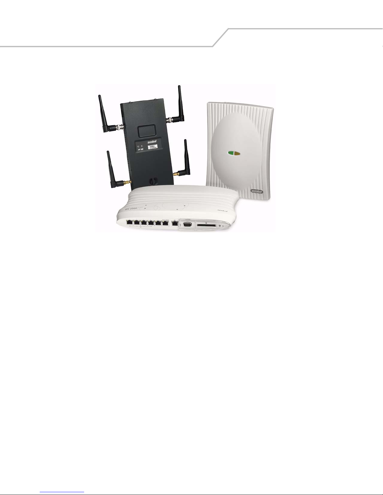
The WS 2000 Wireless Switch provides a low-cost, feature-rich option for sites with one to six Access Ports. The WS 2000
Wireless Switch works at the center of a network’s infrastructure to seamlessly and securely combine wireless LANs
(WLANs) and wired networks. The switch sits on the network. Wireless Access Ports connect to one of the six available
ports on the switch and the external wired network (WAN) connects to a single 10/100 Mbit/sec. WAN port.
Mobile units (MUs) associate with the switch via an Access Port. When an MU contacts the switch, the switch cell controller
services attempt to authenticate the device for access to the network.
The WS 2000 Wireless Switch acts as a WAN/LAN gateway and a wired/wireless switch.
Management of Access Ports
This wireless switch provides six 10/100 Mbit/sec. LAN ports for internal wired or wireless traffic. Four of these ports
provide IEEE 802.3af-compliant Power over Ethernet (PoE) support for devices that require power from the Ethernet
connection (such as Access Ports). Administrators can configure the six ports to communicate with a private LAN or with an
Access Port for a wireless LAN (WLAN). The switch provides up to four extended service set identifiers (ESSIDs) for each
Access Port connected to the switch.
Product Overview 1-3
Firewall Security
The LAN and Access Ports are placed behind a user-configurable firewall that provides stateful packet inspection. The
wireless switch performs network address translation (NAT) on packets passing to and from the WAN port. This combination
provides enhanced security by monitoring communication with the wired network.
Wireless LAN (WLAN) Security
Administrators can configure security settings independently for each ESSID. Security settings and protocols available with
this switch include:
• Kerberos
•WEP-40
• WEP-128
• 802.1x with RADIUS
• 802.1x with Shared Key
•KeyGuard
•WPA
• WPA2/CCMP
VPN Security
Virtual Private Networks (VPNs) are IP-based networks that use encryption and tunneling to give users remote access to a
secure LAN. In essence, the trust relationship is extended from one LAN across the public network to another LAN, without
sacrificing security. A VPN behaves similarly to a private network; however, because the data travels through the public
network, it needs several layers of security. The WS 2000 Wireless Switch acts as a robust VPN gateway.
Page 18

WS 2000 Wireless Switch System Reference Guide1-4
Hardware Overview
The WS 2000 Wireless Switch provides a fully integrated solution for managing every aspect of connecting wireless LANs
(WLANs) to a wired network. This wireless switch can connect directly to a cable or DSL modem, and can also connect to
other wide area networks through a Layer 2/3 device (such as a switch or router). The switch includes the following features:
• One WAN (RJ-45) port for connection to a DSL modem, cable modem, or any other Layer 2/3 network device.
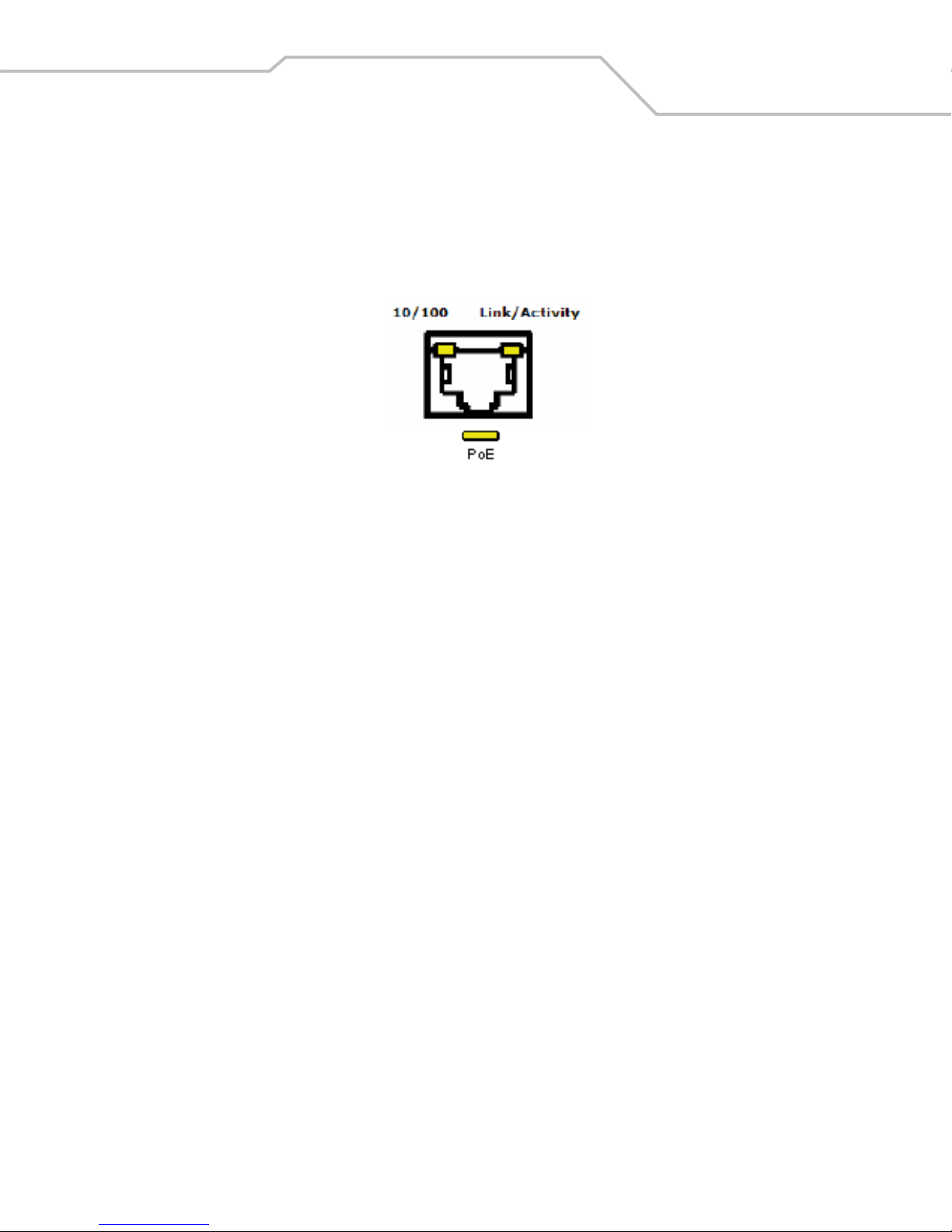
• Six 10/100 Mbit/sec. LAN (RJ-45) ports: four ports provide 802.3af “Power over Ethernet” (PoE) support; the other two
do not provide power.
• Each port has two LEDs, one indicating the speed of the transmission (10 or 100 Mbit/sec.), the other indicating whether
there is activity on the port. The four LAN ports with PoE have a third LED that indicates whether power is being
delivered over the line to a power device (such as an Access Port). (See the WS 2000 Wireless Switch LED explanation
for more information on the meaning of the different state of the LEDs.)
• A DB-9 serial port for direct access to the command-line interface from a PC. Use Symbol’s Null-Modem cable (Part No.
25-632878-0) for the best fitting connection.
• A CompactFlash slot that provides AirBEAM
Technical Specifications
®
support.
Physical Specifications
• Width: 203 mm
• Height: 38 mm
• Depth: 286 mm
• Weight: 0.64 kg
Power Specifications
• Maximum Power Consumption: 90-256 VAC, 47-63 Hz, 3A
• Operating Voltage: 48 VDC
• Operating Current: 1A
• Peak Current: 1.6A
Environmental Specifications
• Operating Temperature: 0ºC to 40ºC
• Storage Temperature: -40ºC to 70ºC
• Operating Humidity: 10% to 85% Non-condensing
• Storage Humidity: 10% to 85% Non-condensing
• Operating Altitude: 2.4 km
• Storage Altitude: 4.6 km
Page 19
WS 2000 Wireless Switch LED Functions
The switch has a large blue LED on the right front that indicates that the switch is powered on.
Each port on the WS 2000 Wireless Switch has either two or three LEDs that indicate the status of the port. Ports 1-4, which
supply 802.3af Power over Ethernet (PoE), have three LEDs. The remaining two non-powered LAN ports and the WAN port
have two LEDs.
Location Function
Upper left LED This LED is present on all ports and indicates the speed of the transmissions through the
port. The LED is on when the transmission rate is 100 Mbit per second (100BaseT). The
light is off when the transmission rate is 10 Mbit per second.
Upper right LED This LED indicates activity on the port. This light is solid yellow when a link to a device is
made. The light flashes when traffic is being transferred over the line.
Lower LED This LED is only present on Ports 1-4. These ports provide 802.3af Power over Ethernet
(PoE) support to devices (such as Access Ports). The LED has several states:
OFF—A non-power device (or no device) is connected; no power is being delivered.
GREEN—The switch is delivering 48 volts to the power device connected to that port.
RED—There was a valid PoE connection; however, the switch has detected that the power
device is faulty. The red light will remain until a non-faulty connection is made to the port.
Product Overview 1-5
Page 20

WS 2000 Wireless Switch System Reference Guide1-6
Software Overview
The WS 2000 Wireless Switch software provides a fully integrated solution for managing every aspect of connecting
Wireless LANs (WLANs) to a wired network, and includes the following components:
Operating System (OS) Services
Operating System (OS) Services determine how the WS 2000 Wireless Switch communicates with existing network and
operating system-centric software services, including:
• Dynamic Host Configuration Protocol (DHCP)
• Telnet and File Transfer Protocol (FTP/TFTP) servers
• The Simple Network Time Protocol (SNTP) client, used to keep switch time synchronized for Kerberos authentication
• A mechanism for setting up a redundant (secondary) switch that takes over if the primary switch fails
Cell Controller Services
The Cell Controller provides the ongoing communication between mobile units (MUs) on the Wireless LAN (WLAN) and the
wired network. Cell Controller services perform the following:
• Initialize the Access Ports
• Maintain contact with Access Ports by sending a synchronized electronic “heartbeat” at regular intervals
• Track MUs when they roam from one location to another
• Manage security schemes based on system configuration
• Maintain system statistics
• Store policies and Access Port information
• Detect and manage rogue Access Ports
• Management of communications QoS
Gateway Services
Gateway services provide interconnectivity between the Cell Controller and the wired network, and include the following:
• System management through a Web-based Graphical User Interface (GUI) and SNMP
• 802.1x RADIUS client
• Security, including Secure Sockets Layer (SSL) and Firewall
• Network Address Translation (NAT), DHCP services, and Layer 3 Routing
• Virtual Private Network (VPN)
Page 21

2
Getting Started
Getting Started with the WS 2000 Wireless Switch. . . . . . . . . . . . . . . . . . . . . . . . . . . . . . . . . . . . . . . . . . . . . .2-2
Step 1: Install the Switch. . . . . . . . . . . . . . . . . . . . . . . . . . . . . . . . . . . . . . . . . . . . . . . . . . . . . . . . . . . . . . . . . . .2-2
Step 2: Set Up Administrative Communication to the Switch. . . . . . . . . . . . . . . . . . . . . . . . . . . . . . . . . . . . . . . 2-2
Step 3: Set the Basic Switch Setting. . . . . . . . . . . . . . . . . . . . . . . . . . . . . . . . . . . . . . . . . . . . . . . . . . . . . . . . . .2-4
Step 3: Set the Basic Switch Setting. . . . . . . . . . . . . . . . . . . . . . . . . . . . . . . . . . . . . . . . . . . . . . . . . . . . . . . . . .2-4
Step 4: Configure the LAN Interface . . . . . . . . . . . . . . . . . . . . . . . . . . . . . . . . . . . . . . . . . . . . . . . . . . . . . . . . . . 2-5
Enable Subnet1 . . . . . . . . . . . . . . . . . . . . . . . . . . . . . . . . . . . . . . . . . . . . . . . . . . . . . . . . . . . . . . . . . . . . . . 2-5
Step 5: Configure Subnet1 . . . . . . . . . . . . . . . . . . . . . . . . . . . . . . . . . . . . . . . . . . . . . . . . . . . . . . . . . . . . . . . . . . 2-6
Step 6: Configure the WAN Interface . . . . . . . . . . . . . . . . . . . . . . . . . . . . . . . . . . . . . . . . . . . . . . . . . . . . . . . . . 2-6
Communicating with the Outside World . . . . . . . . . . . . . . . . . . . . . . . . . . . . . . . . . . . . . . . . . . . . . . . . . . .2-7
Setting Up Point-to-Point over Ethernet (PPPoE) Communication . . . . . . . . . . . . . . . . . . . . . . . . . . . . . . . . 2-8
Step 7: Enable Wireless LANs (WLANs) . . . . . . . . . . . . . . . . . . . . . . . . . . . . . . . . . . . . . . . . . . . . . . . . . . . . . . .2-8
Wireless Summary Area . . . . . . . . . . . . . . . . . . . . . . . . . . . . . . . . . . . . . . . . . . . . . . . . . . . . . . . . . . . . . . . 2-9
Step 8: Configure WLAN Security . . . . . . . . . . . . . . . . . . . . . . . . . . . . . . . . . . . . . . . . . . . . . . . . . . . . . . . . . . . .2-9
Setting the Authentication Method . . . . . . . . . . . . . . . . . . . . . . . . . . . . . . . . . . . . . . . . . . . . . . . . . . . . . . 2-10
Setting the Encryption Method . . . . . . . . . . . . . . . . . . . . . . . . . . . . . . . . . . . . . . . . . . . . . . . . . . . . . . . . .2-10
Mobile Unit Access Control List (ACL). . . . . . . . . . . . . . . . . . . . . . . . . . . . . . . . . . . . . . . . . . . . . . . . . . . . 2-11
Step 9: Test Connectivity . . . . . . . . . . . . . . . . . . . . . . . . . . . . . . . . . . . . . . . . . . . . . . . . . . . . . . . . . . . . . . . . . .2-11
Where to Go from Here? . . . . . . . . . . . . . . . . . . . . . . . . . . . . . . . . . . . . . . . . . . . . . . . . . . . . . . . . . . . . . . . . . . 2-12
Page 22

WS 2000 Wireless Switch System Reference Guide2-2
Getting Started with the WS 2000 Wireless Switch
This section provides just enough instruction to set up the WS 2000 Wireless Switch, connect an Access Port, and test
communications with a single mobile unit (MU) and the wide area network (WAN). The configuration suggestions made here
are just the minimum needed to test the hardware. Once finished with this section, additional configuration settings are
required. This section covers the following topics:
• Step 1: Install the switch and connect it to the WAN, a
standalone computer, and an Access Port
• Step 2: Set up administrative communication to the
switch
• Step 3: Set the basic switch settings
• Step 4: Configure the LAN interface
Step 1: Install the Switch
To install the WS 2000 Wireless Switch hardware, follow the directions in the WS 2000 Wireless Switch Quick Installation
Guide found in the box with the switch and on the CD-ROM that is distributed with the switch. These instructions describe
how to:
• Select a site (desk, wall, or rack) for the switch
• Install the switch using the appropriate accessories for the selected location
• Connect devices to WAN and LAN ports (using standard CAT-5 cables)
• Interpret the port LEDs on the front of the switch
After the switch is mounted and powered up, connect the following items to the switch:
1. Connect the WAN to the switch (using the WAN port) with a CAT-5 Ethernet cable. The LEDs for that port should start
to flash.
• Step 5: Configure Subnet1
• Step 6: Configure the WAN Interface
• Step 7: Enable Wireless LANs (WLANs)
• Step 8: Configure WLAN Security
• Step 9: Test Connectivity
2. Connect an Access Port to the switch using a CAT-5 Ethernet cable using one of the six LAN ports. If the Access Port
requires PPPoE, connect the Access Port in ports 1, 2, 3, or 4. Ports 5 and 6 do not provide power.
3. Have a mobile “wireless” device available to test communication with the Access Port.
Access Ports must be connected to the LAN ports of the wir eless switc h to enable co nfigurati on
of the Access Port related settings.
Step 2: Set Up Administrative Communication to the Switch
Before the configuration process can begin, establish a link with the wireless switch.
1. Connect a “wired” computer to the switch (in any one of the available LAN ports) using a standard CAT-5 cable.
2. Set up the computer for TCP/IP DHCP network addressing and make sure that the DNS settings are not hardcoded.
3. Start up Internet Explorer (with Sun Micro systems’ Java Runtime Environment (JRE) 1.4 or higher installed) and type
the following IP address in the address field: 192.168.0.1
For optimum compatibility use Sun Microsystems’ JRE 1.4 or higher (available from Sun’s
website), and be sure to disable Microsoft’s Java Virtual Machine if it is installed.
The following screen is displayed.
Page 23
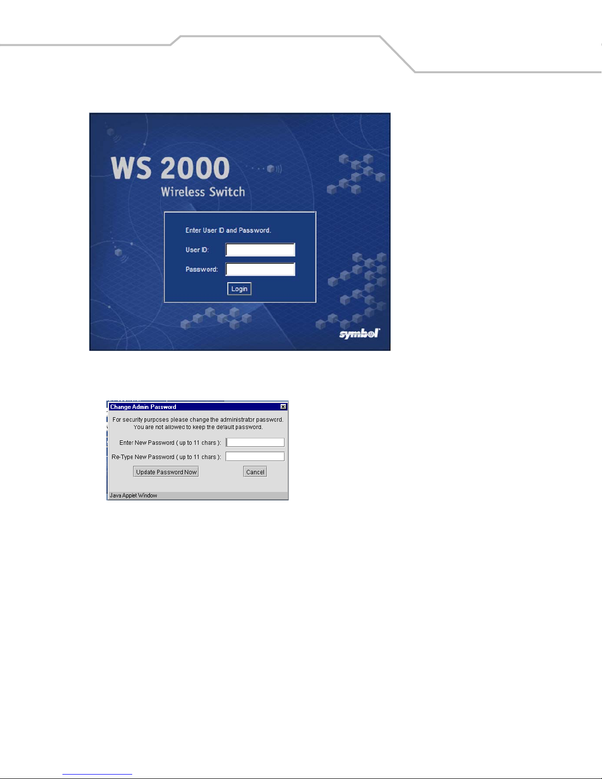
Getting Started 2-3
4. Log in using “admin” as the User ID and “symbol” as the Password.
5. If the login is successful, the following dialog window is displayed.
Enter a new admin password in both fields, and click the Update Password Now button. When the admin password
has been updated, the System Settings screen is displayed.
Page 24
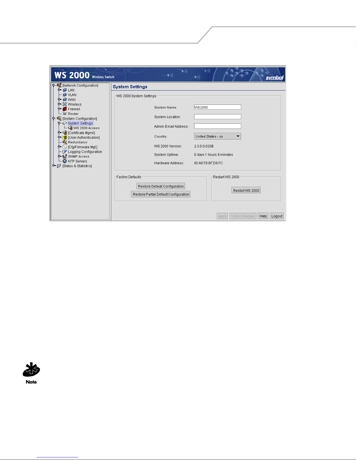
WS 2000 Wireless Switch System Reference Guide2-4
Step 3: Set the Basic Switch Setting
1. Enter a System Name for the wireless switch. The specified name appears in the lower-left corner of the configuration
screens, beneath the navigation tree. This name can be a useful reminder if multiple Symbol wireless switches are
being administered.
2. Enter a text description of the location of the switch in the System Location field. This text is used as a reminder to
the network administrator and is also used to set the location variable if the switch is administered using SNMP.
3. Enter an email address for the administrator in the Admin Email Address field. The switch uses this address for
sending SNMP-related and other administration-related messages to the administrator.
4. Select the Country for the switch from the drop-down menu. Selecting the correct country is extremely important. Each
country has its own regulatory restrictions concerning electromagnetic emissions and the maximum RF signal strength
that can be transmitted by Access Ports. To ensure compliance with national and local laws, be sure to set this field
accurately.
5. Click Apply to save changes. Unapplied changes are lost if the administrator navigates to a different screen.
The WS 2000 switch is shipped with an open default SNMP configuration:
Community: public, OID: 1.3.6.1, Access: Read-only
Community: private, OID: 1.3.6.1, Access: Read-write
If your switch has these settings, it is important to change them immediately; otherwise, users
on the same network will have read-write access to the switch through the SNMP interface.
Select System Configuration --> SNMP Access from the left menu to examine the settings and
change them, if neces sary.
Page 25
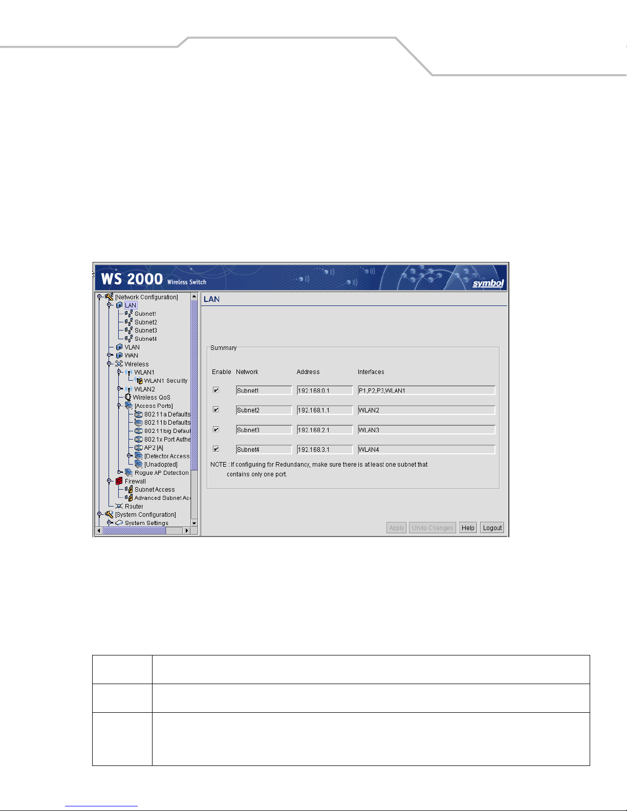
Step 4: Configure the LAN Interface
The first step of network configuration process is to figure out the topology of the LAN. The WS 2000 Wireless Switch allows
the administrator to enable and configure four different subnets. The administrator can assign an IP address, port
associations, and DHCP settings for each subnet.
Enable Subnet1
Select LAN under the Network Configuration group from the left menu. Use the LAN configuration screen to view a summary
of physical-port addresses and wireless LANs (WLANs) associated with the four supported subnets, and to enable or disable
each configured subnet.
Getting Started 2-5
1. In the LAN screen, the administrator can enable up to four subnets. Make sure that the checkbox to the left of the
Subnet1 line is enabled.
Each enabled subnet shows up in the directory tree in the left column of the configuration screens. Consider disabling
a previously configured subnet if its assigned ports are no longer in use, or to consolidate the LAN’s communications
on fewer subnets.
The rest of the information on this screen is summary information; it is collected from other screens (such as the subnet
configuration screens) where the administrator can set the data.
Network
Address
Interfaces
Network (subnet) name is a descriptive string that should describe the subnet’s function. The WS 2000 Network Management
System uses subnet names throughout the configurations screens.
This IP address allows users from outside the subnet (whether from the WAN or from another subnet from the same switch) to
access the right subnet. An IP address uses a series of four numbers that are expressed in dot notation, for example, 194.182.1.1.
The Interfaces field displays which of the six physical LAN ports are associated with the subnet. The possible ports are: P1 (port
1), P2, P3, P4, P5, and P6 (from left to right facing the front of the switch). The administrator assigns a port to a subnet to enable
access to the device(s) connected to that port. The administrator can assign a port to only one subnet.
The Interfaces field also lists the WLANs that are associated with the subnet.
Page 26
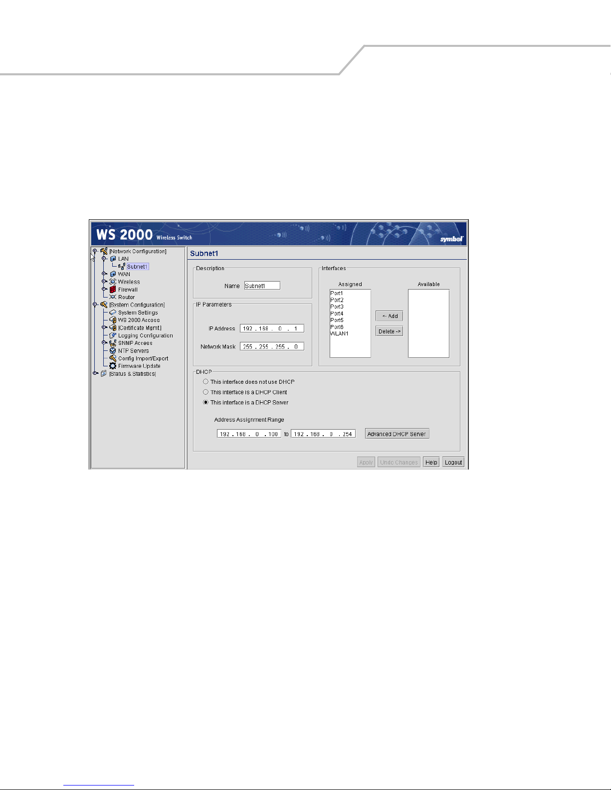
WS 2000 Wireless Switch System Reference Guide2-6
Step 5: Configure Subnet1
The WS 2000 Network Management System allows the administrator to define and refine the configuration of the enabled
subnets. Each of four subnets (short for “subnetworks”) can be configured as an identifiably separate part of the switchmanaged local area network (LAN). Each subnet can include some combination of assigned ports and associated wireless
LANs (WLANs).
1. Select Network Configuration --> LAN --> Subnet1 from the list on the left. The following screen appears for the
selected subnet.
2. Check to make sure that all the ports and WLAN1 are selected for this subnet. WLAN1 should automatically be included
if the switch and the Access Port are communicating properly. If WLAN1 is not present in the list, check the following:
• The power to the Access Port
• The connections between the switch and the Access Port
• The LEDs to make sure that lights are on and flashing
3. For this initial configuration, ensure that This interface is a DHCP Server is enabled. If so, the switch sets the IP
addresses automatically for the mobile devices. This value can be changed at any time in the future. All other default
settings are fine for the system test.
DHCP is a protocol that includes mechanisms for IP address allocation and delivery of host-specific configuration
parameters from a DHCP server to a host. Some of these parameters are IP address, network mask, and gateway. The
switch includes internal DHCP server and client features, and the subnet’s interface can use either capability.
4. Click the Apply button to save changes.
Step 6: Configure the WAN Interface
A wide area network (WAN) is a widely dispersed telecommunications network. In a corporate environment, the WAN port
might connect to a larger corporate network. For a small business, the WAN port might connect to a DSL or cable modem to
access the Internet.
Page 27
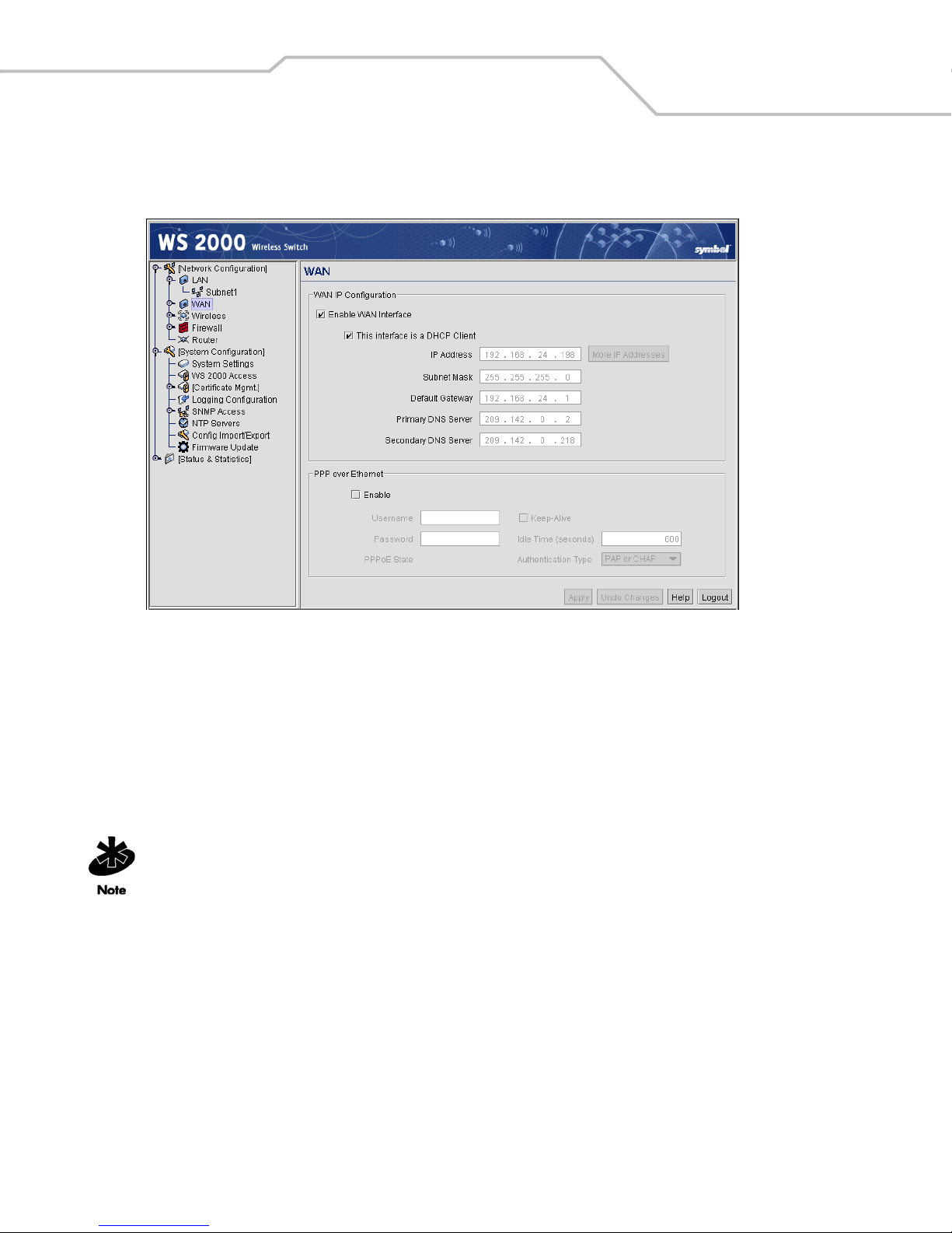
Getting Started 2-7
The WS 2000 Wireless Switch includes one WAN port. In order to set up communications with the outside world, select
Network Configuration --> WAN from the left menu. The following WAN configuration page appears.
Communicating with the Outside World
1. Click the Enable WAN Interface checkbox to enable a connection between the switch and a larger network or the
outside world through the WAN port.
2. If this switch should be a DHCP client (get its IP address automatically from another server or switch), check the This
interface is a DHCP Client checkbox. If This interface is DHCP Client is checked, the switch is limited to one WAN
IP address. This choice is required when:
• The host router or switch on the WAN is communicating with the WS 2000 Wireless Switch using DHCP.
• The switch is interfacing with an Internet Service Provider (ISP) that uses DHCP addressing.
This setting is independent from the DHCP settings for the switch’s internal subnets.
3. If This interface is DHCP Client is not checked, fill in the information in this area. To find out the information to enter
into these fields, contact the network administrator or the ISP that provided the cable modem or DSL router. All the fields
below take standard IP addresses of the form xxx.xxx.xxx.xxx.
• The IP Address refers to the IP address that the outside world uses to address the WS 2000 Wireless Switch.
• Click the More IP Addresses button to specify additional static IP addresses for the switch. Additional IP
addresses are required when users within the LAN need dedicated IP addresses, or when servers in the LAN need
to be accessed (addressed) by the outside world. The pop-up window allows the administrator to enter up to eight
WAN IP addresses for the switch.
• The Subnet Mask is the mask used for the WAN.
• The Default Gateway is the address of the device that provides the connection to the WAN (often a cable modem
or DSL router).
Page 28

WS 2000 Wireless Switch System Reference Guide2-8
• The two DNS Server fields specify DNS addresses of servers that can translate domain names, such as
www.symbol.com, into IP addresses that the network uses when passing information. The Secondary DNS Server
acts as a backup to the Primary DNS Server when the primary server is not responding.
Setting Up Point-to-Point over Ethernet (PPPoE) Communication
PPPoE provides the ability to connect a network of hosts through a simple device to a remote access concentrator. Many DSL
providers require that their clients communicate using this protocol. The facility allows the ISP to control access, billing, and
type of service provided to clients on a per-user or per-site basis. Check with the network administrator or ISP to determine
whether to enable this feature, and, if so, find out the username and password required for authentication.
1. Check Enable in the PPP over Ethernet area to enable the PPPoE protocol for high-speed connections.
2. Enter the Username and Password required for authentication. The username and password are for the switch’s
router to use when connecting to the ISP. When the Internet session starts, the ISP authenticates the username.
3. Set the Idle Time to an appropriate number. This number is the amount of time the PPPoE connection will be idle before
it disconnects. The 10000 second (default idle time is appropriate for most situations).
4. Check Keep Alive to instruct the switch to continue occasional communications over the WAN even when client
communications to the WAN are idle. Some ISPs terminate inactive connections, while others do not. In either case,
enabling Keep-Alive mode keeps the switch’s WAN connection alive, even when there is no traffic. If the ISP drops the
connection after so much idle time, the switch automatically reestablishes the connection to the ISP.
5. Select the appropriate WAN authentication method from the drop-down menu. Collect this information from the
network administrator. Select between None, PAP, CHAP, or PAP or CHAP.
CHAP
PAP
A type of authentication in which the person logging in uses secret information and some special mathematical operations to
come up with a number value. The server the person is logging into knows the same secret value and performs the same
mathematical operations. If the results match, the person is authorized to access the server. One of the numbers in the
mathematical operation is changed after every log-in, to protect against an intruder secretly copying a valid authentication
session and replaying it later to log in.
An identity verification method used to send a username and password over a network to a computer that compares the username
and password to a table listing authorized users. This method of authentication is less secure, because the username and
password travel as clear text that a hacker could read.
6. Click the Apply button to save changes.
Step 7: Enable Wireless LANs (WLANs)
The WS 2000 Wireless Switch works either in a wired or wireless environment; however, the power of the switch is
associated with its support of wireless networks. In order to use the wireless features of the switch, the administrator needs
to enable up to four wireless LANs (WLANs).
To start the WLAN configuration process, select the Network Configuration --> Wireless item from the left menu. The
following Wireless summary screen appears.
Page 29
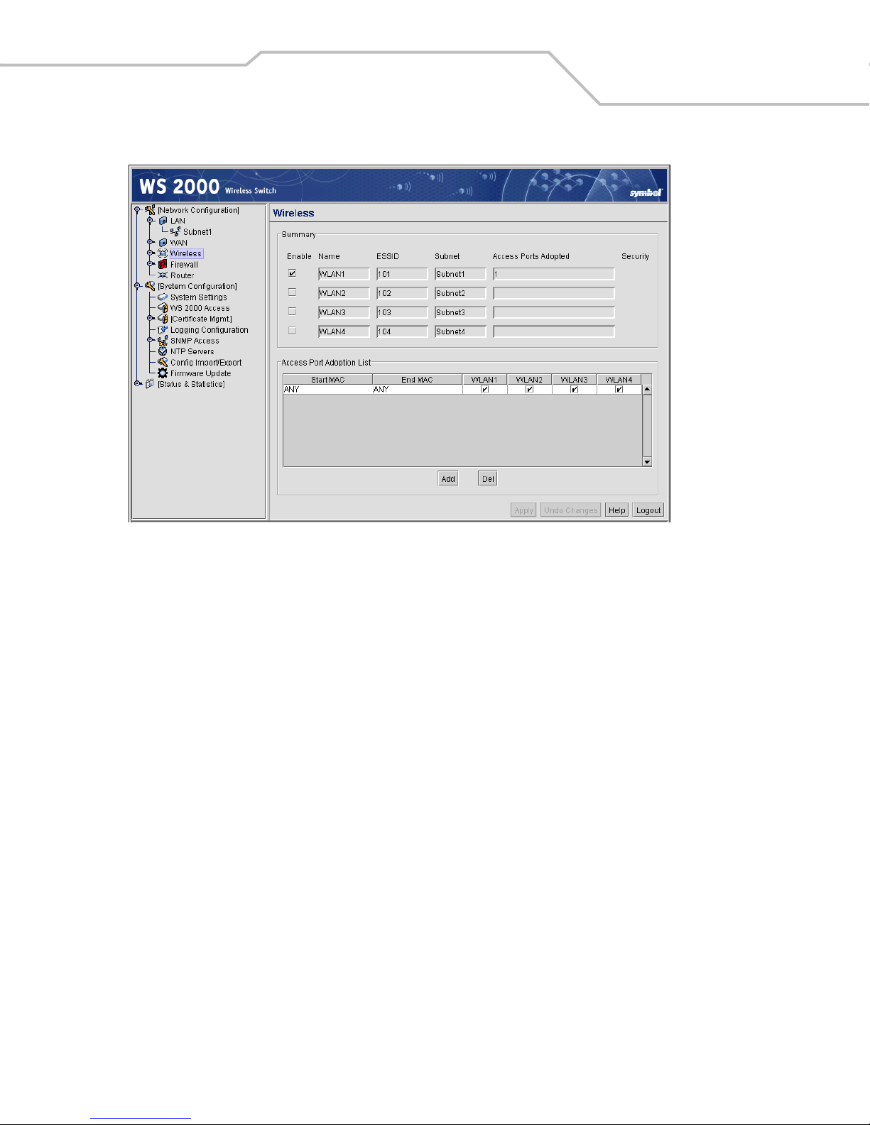
Getting Started 2-9
Wireless Summary Area
The top portion of the window displays a summary of the WLANs that are currently defined. This is the screen in which the
administrator can enable or disable a WLAN. At first, four WLANs are listed WLAN1, WLAN2, WLAN3, and WLAN4;
however, only WLAN1 is enabled.
1. Verify that WLAN1 is enabled (checked) and associated with Subnet1.
2. Verify that Access Port 1 is shown in the Access Ports Adopted field to the right. If it is not, verify the connection
between the switch and the Access Port.
The current settings for the associated Subnet and adopted Access Ports are displayed on this screen; however, the screen
associated with each WLAN (under Network Configuration --> Wireless) is where the settings and rules for adopting
Access Ports can be modified.
Use the Access Port Adoption area to assign Access Ports to a particular WLAN. The switch can adopt up to six Access Ports
at a time, but the list of allowed Access Port addresses (displayed in this area) can exceed six in number. A dual-radio
802.11a/b Access Port counts as one Access Port with respect to the maximum allowed; however, each radio is listed as a
separate Access Port.
This adoption list identifies each Access Port by its Media Access Control (MAC) address. This address is the Access Port’s
hard-coded hardware number that is printed on the bottom of the device. An example of a MAC address is
00:09:5B:45:9B:07.
The default setting associates all adopted Access Ports with WLAN1.
Step 8: Configure WLAN Security
In the previous step, the administrator set parameters for each WLAN that fine tune the performance of the WLAN. In
addition, the administrator can set the type and level of security for each WLAN. These security measures do not control
communications from the WAN; instead, they control communication from the clients within the WLAN.
Page 30
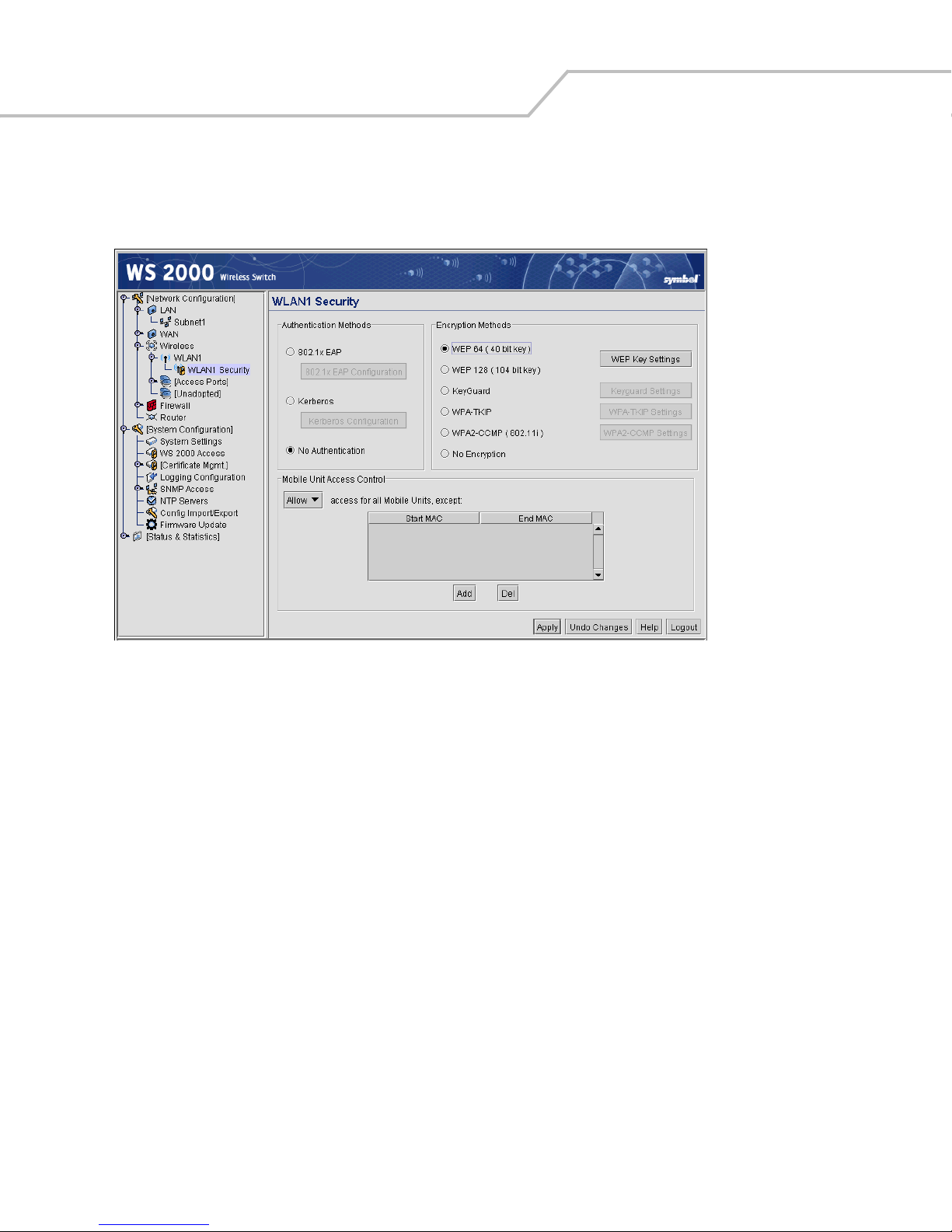
WS 2000 Wireless Switch System Reference Guide2-10
In the Network Configuration --> Wireless --> <WLAN name> --> <WLAN Name> --> Security screen, the administrator
can set the user authentication method and the encryption method, as well as define a set of rules that control which MUs
can communicate through the WLAN.
Setting the Authentication Method
The authentication method sets a challenge-response procedure for validating user credentials such as username,
password, and sometimes secret-key information. The WS 2000 Wireless Switch provides two methods for authenticating
users: 802.1x EAP and Kerberos. The administrator can select between these two methods. For testing connectivity, WLAN
security is not an issue, so there is not reason to enable authentication—the default setting (No Authentication) is
sufficient.
Setting the Encryption Method
Encryption applies a specific algorithm to data to alter its appearance and prevent unauthorized reading. Decryption applies
the algorithm in reverse to restore the data to its original form. Sender and receiver employ the same encryption/decryption
method.
Wired Equivalent Privacy (WEP) is a security protocol specified in the IEEE Wireless Fidelity (Wi-Fi) standard, 802.11b. WEP
is designed to provide a WLAN with a level of security and privacy comparable to that of a wired LAN. WEP might be all that
a small-business user needs for the simple encryption of wireless data. However, networks that require more security are
at risk from a WEP flaw. An unauthorized person with a sniffing tool can monitor a network for less than a day and decode
its encrypted messages.
For the connectivity test, set WEP 128 encryption. This ensures that communications with the switch are secure enough for
this stage. Later on, increasing the security level might be necessary.
1. Select the WEP 128 (104-bit key) option.
2. To use WEP encryption with the No Authentication selection, click the WEP Key Settings button to display a subscreen for entering keys.
Page 31

Getting Started 2-11
3. Add a key to Key #1, and use that key with the mobile unit. The keys consist of 26 hexadecimal (0-9, A-E) characters.
When finished, click the Ok button to close this screen an return to the WLAN Security screen.
4. Click the Apply button in the WLAN Security screen to save changes.
Mobile Unit Access Control List (ACL)
This list is used to specify which mobile units can or cannot gain access to the WLAN. The list employs an adoption rule for
allowing or denying specific mobile units by way of exception. By default, all mobile units can gain access.
Step 9: Test Connectivity
At this point, the switch is set up to allow mobile units to access the LAN.
1. Go to the mobile unit and ensure that it is set up as a DHCP client.
2. Set the mobile unit for WEP 128 encryption and set the same key as the one that was entered in the WEP Key Settings
dialog. It may be necessary to reboot the mobile unit after changing the settings.
3. Open a Web browser and type the IP address: 192.168.0.1.
The WS 2000 Switch Management screen should appear. If not, go back to the wired system used to configure the
switch and see if the mobile device appears in the MU Stats screen (Status & Statistics --> MU Stats). If it does not
appear on the MU Stats screen, recheck the network and WEP settings on the mobile device.
4. In the Web browser, enter a URL for a site (such as www.symbol.com) on the WAN. If the site does not appear, go to
the WAN Stats screen (Status & Statistics --> WAN Stats) to review the status of the WAN connection.
Page 32

WS 2000 Wireless Switch System Reference Guide2-12
Where to Go from Here?
When full connectivity has been verified, the switch can be fully configured to meet the needs of the organization. Refer to
the two case studies provided with this reference for specific installation examples. These case studies describe the
environment, the desired features, and the configuration selections that were made in two different scenarios.
• Case 1: Retail Use Case
(with handheld terminals, wireless printers, wired POS, secured access to in-store server, and public access to WAN)
• Case 2: Field Office Use Case
(with 3 WAN IP addresses, VPN passthrough, RADIUS server, and full-access between subnets)
Page 33

3
LAN/Subnet Configuration
Enabling Subnets for the LAN Interface . . . . . . . . . . . . . . . . . . . . . . . . . . . . . . . . . . . . . . . . . . . . . . . . . . . . . . . 3-2
Defining Subnets . . . . . . . . . . . . . . . . . . . . . . . . . . . . . . . . . . . . . . . . . . . . . . . . . . . . . . . . . . . . . . . . . . . . .3-2
Configuring Subnets. . . . . . . . . . . . . . . . . . . . . . . . . . . . . . . . . . . . . . . . . . . . . . . . . . . . . . . . . . . . . . . . . . . . . . . 3-3
The DHCP Configuration . . . . . . . . . . . . . . . . . . . . . . . . . . . . . . . . . . . . . . . . . . . . . . . . . . . . . . . . . . . . . . . 3-4
Advanced DHCP Settings. . . . . . . . . . . . . . . . . . . . . . . . . . . . . . . . . . . . . . . . . . . . . . . . . . . . . . . . . . . . . . .3-5
Configuring Subnet Access . . . . . . . . . . . . . . . . . . . . . . . . . . . . . . . . . . . . . . . . . . . . . . . . . . . . . . . . . . . . . . . . . 3-5
The Access Overview Table . . . . . . . . . . . . . . . . . . . . . . . . . . . . . . . . . . . . . . . . . . . . . . . . . . . . . . . . . . . . . 3-6
The Access Exception Area . . . . . . . . . . . . . . . . . . . . . . . . . . . . . . . . . . . . . . . . . . . . . . . . . . . . . . . . . . . . .3-6
Advanced Subnet Access Settings . . . . . . . . . . . . . . . . . . . . . . . . . . . . . . . . . . . . . . . . . . . . . . . . . . . . . . . . . . . 3-8
Virtual LAN (VLAN) Configuration . . . . . . . . . . . . . . . . . . . . . . . . . . . . . . . . . . . . . . . . . . . . . . . . . . . . . . . . . . . 3-11
Page 34

WS 2000 Wireless Switch System Reference Guide3-2
Enabling Subnets for the LAN Interface
The WS 2000 Wireless Switch allows the administrator to enable and configure four different subnets. The administrator
can assign a IP address, port associations, DHCP settings, and security settings for each subnet. This System Reference
provides two case studies that demonstrate how requirements for network access and capabilities drive the decisions of
how to configure the subnets.
Defining Subnets
Select LAN under the Network Configuration group from the left menu. Use the LAN configuration screen to view a
summary of physical-port addresses and Wireless LANs (WLANs) associated with the four supported subnets, and to enable
or disable each configured subnet.
1. Check the box to the left of a subnet to enable that subnet. Up to four subnets can be enabled to use the wired and/or
wireless connections of the switch-managed LAN. Enable multiple subnets to divide the communications of different
business areas or operations. Each enabled subnet shows up in the directory tree in the left column of the configuration
screens. Consider disabling a previously configured subnet if its assigned ports are no longer in use, or to consolidate
the LAN’s communications on fewer subnets.
2. Click Apply to save changes. All “unapplied” changes are lost when the administrator moves to a new screen.
The rest of the information on this screen is summary information. It is collected from other screens (such as the subnet
configuration screens) where the administrator can set the data.
Page 35

LAN/Subnet Configuration 3-3
Network
Network (subnet) name is a descriptive string that should describe the subnet’s function. The WS 2000
Network Management System uses subnet names throughout the configurations screens.
Address
This IP address allows users from outside the subnet (whether from the WAN or from another subnet
from the same switch) to access the right subnet. An IP address uses a series of four numbers that are
expressed in dot notation, for example, 194.182.1.1.
Interfaces
The Interfaces field displays which of the six physical LAN ports are associated with the subnet. The
possible ports are: P1 (port 1), P2, P3, P4, P5, and P6 (from left to right facing the front of the switch).
The administrator assigns a port to a subnet to enable access to the device(s) connected to that port. The
administrator can assign a port to only one subnet.
The Interfaces field also lists the WLANs that are associated with the subnet.
To change features of a subnet select Network Configuration --> LAN --> <subnet name> from the menu on the left.
Configuring Subnets
The WS 2000 Network Management System allows the administrator to define and refine the configuration of the enabled
subnets. Each of three subnets (short for “subnetworks”) can be configured as an identifiably separate part of the switchmanaged Local Area Network (LAN). Each subnet can include some combination of assigned ports and associated Wireless
LANs (WLANs).To configure an enabled subnet, select the subnet name from the Network Configuration --> LAN list in
the left. The following screen appears for the selected subnet.
1. Change the Name of the subnet to use a descriptive name that indicates something about the subnet. The name can
contain seven characters, including spaces and numbers. It will appear in the left menu under the LAN menu item.
Page 36

WS 2000 Wireless Switch System Reference Guide3-4
2. Set an IP address to be used for the subnet. This is how the switch will refer specifically to this subnet. This could be
a WAN address; but more likely it will be a non-routable address. An IP address uses a series of four numbers that are
expressed in dot notation, for example, 194.182.1.1.
3. Set the Network Mask for the IP address. A network mask uses a series of four numbers that are expressed in dot
notation, similar to an IP number. For example, 255.255.255.0 is a network mask.
4. Select a port or WLAN from the Interfaces drop-down menu to associate it with the subnet. Six LAN ports are available
on the switch. Assign from one to six ports to a subnet. Two subnets cannot use the same port. However, multiple ports
can be assigned to one subnet.
Four WLANs are available. WLAN assignments are logical designations. Associate from zero to three WLANs with a
subnet. Two subnets cannot use the same WLAN. However, multiple WLANs can be associated with one subnet. If two
or three WLANs are associated with one subnet, each port dedicated to that subnet can use any of the associated
WLANs.
5. Click the Add button to add it to the Interfaces list.
Note that wireless devi ces cannot access the swi tch unless a WLAN is configur ed and associated
with a subnet. (This process is described in Configuring Wireless LANs.)
The DHCP Configuration
DHCP is a protocol that includes mechanisms for IP address allocation and delivery of host-specific configuration parameters
from a DHCP server to a host. Some of these parameters are IP address, network mask, and gateway. The switch includes
internal DHCP server and client features, and the subnet’s interface can use either capability.
1. Click the appropriate radio button to select one DHCP setting for the subnet’s interfaces:
• Select This interface does not use DHCP to disable DHCP on this subnet and specify IP addresses manually.
• Select This interface is a DHCP Client if this subnet obtains IP parameters from a DHCP server outside the
switch.
• Select This interface is a DHCP Server to enable the switch’s DHCP server features.
2. If This interface is a DHCP Server is the selected option, fill in the Address Assignment Range fields. These fields
allow the administrator to assign a range of IP addresses to devices as they connect.
3. Set the Advanced Settings, if necessary.
4. Click the Apply button to save all changes.
Page 37

Advanced DHCP Settings
1. Click the Advanced DHCP Server button to display a sub-screen
to further customize IP address allocation.
2. Specify the address of a Primary DNS Server. The Internet Server
Provider (ISP) or a network administrator can provide this address. A
DNS server translates a domain name, such as www.symbol.com,
into an IP address that networks can use.
3. Specify the address of a Secondary DNS Server if one is
available.
4. Specify a DHCP Lease Time period in seconds for available IP
addresses. The DHCP server grants an IP address for as long as it
remains in active use. The lease time is the number of seconds that
an IP address is reserved for re-connection after its last use. Using
very short leases, DHCP can dynamically reconfigure networks in
which there are more computers than there are available IP
addresses. This is useful, for example, in education and customer
environments where mobile-unit users change frequently. Use
longer leases if there are fewer users.
5. Use the Static Mappings table to associate static (or fixed) IP addresses with MAC addresses of specific wireless
devices. Every wireless, 802.11x-standard device has a unique Media Access Control (MAC) address. This address is
the device’s hard-coded hardware number (shown on the bottom or back). An example of a MAC address is
00:09:5B:45:9B:07.
LAN/Subnet Configuration 3-5
This MAC table of specified devices provides corresponding static IP addresses for users, mobile units, and applications
that may prefer or require such access.
Configuring Subnet Access
The WS 2000 Network Management System allows the administrator to set up access rules for subnet-to-subnet and
subnet-to-WAN communication. These access rules control communication between subnets and the outside world (the
WAN). Select Network Configuration --> Firewall --> Subnet Access to get to the Subnet Access screen.
Page 38

WS 2000 Wireless Switch System Reference Guide3-6
The Access Overview Table
In the overview table, each of the rectangles represents a subnet association. The three possible colors indicate the current
access level, as defined, for each subnet association.
Color Access Type Description
Green Full Access
Yellow Limited Access
Red No Access
The Access Exception Area
In the lower half of the screen, the access is controlled by specific rules that control the protocols that are allowed or denied
between the two subnets or the subnet and the WAN. All rules are added to the exception table. The Allow or Deny menu
item applies to all entries in the table. There are two ways to add entries (access rules) to the table. The first is by checking
the checkboxes for specific protocols (on the left). The second is by adding rules for specific port numbers by clicking the
Add button and filling in the necessary information. A combination of the two methods can be used to add multiple entries
to the table.
No protocol exceptions (rules) are specified. All traffic may pass between these two
areas.
One or more protocol rules are specified. Specific protocols are either enabled or disabled
between these two areas. Click the table cell of interest and look at the exceptions area
in the lower half of the screen to determine the protocols that are either allowed or
denied.
All protocols are denied, without exception. No traffic will pass between these two areas.
You can allow or deny communication through specific protocols using the following process:
Page 39

LAN/Subnet Configuration 3-7
1. Click in a cell of the table that represents the subnet-to-subnet (or subnet-to-WAN) relationship to define. All access
rules (if any are defined) appear in the table in the lower-half of the screen.
2. Use the pull-down menu above the list to Allow or Deny all the entries specified in the exception table. You cannot
allow some protocols (or ports) and deny others.
3. From the list of checkboxes on the left side, select those protocols to allow or deny. The protocols are automatically
added to the table with the relevant Name, Transport, Start Port, and End Port information. The available protocols are
shown in the table below.
Protocol Transport,
Port Used
HTTP
TELNET
FTP
SMTP
POP
DNS
TCP, 80 Hypertext Transfer Protocol (HTTP) is the protocol for transferring files on the World
TCP, 23 TELNET is the terminal emulation protocol of TCP/IP. TELNET uses TCP to achieve a
TCP, 21 File Transfer Protocol (FTP) is an application protocol that uses the Internet’s TCP/IP
TCP, 25 Simple Mail Transfer Protocol (SMTP) is a TCP/IP protocol used for sending and receiving
TCP, 109:110 Post Office Protocol (POP3) is a TCP/IP protocol intended to permit a workstation to
TCP+UDP, 53 Domain Name Service (DNS) protocol searches for resources using a database that is
Description
Wide Web. HTTP is an application protocol that runs on top of the TCP/IP suite of
protocols, the foundation protocols for the Internet.
virtual connection between server and client, then negotiates options on both sides of
the connection.
protocols. FTP provides a simple and efficient way to exchange files between computers
on the Internet.
email. Due to its limited ability to queue messages at the receiving end, SMTP is often
used with POP3 or IMAP. SMTP sends the email, and then POP3 or IMAP receives the
email.
dynamically access a maildrop on a server host. A workstation uses POP3 to retrieve
email that the server is holding for it.
distributed among different name servers.
• You can make changes to the information automatically filled into the table; however, note that changes in the
selected transport type can change the port numbers that can be specified in the table.
4. To add an access rule for a protocol, port, or transport other than the ones available from the checkboxes on the left,
click the Add button. An empty row is added to the table.
• Specify a Name to identify the new access rule. This could be the name of a particular application, for example.
• Select a transport type from the Transport column’s pull-down menu. The available transports are:
Transport Description
ALL
This selection designates all of the protocols displayed in the table’s pull-down menu, as described
below.
TCP
Transmission Control Protocol (TCP) is a set of rules used with Internet Protocol (IP) to send data
as message units over the Internet. While IP handles the actual delivery of data, TCP keeps track
of individual units of data called packets. Messages are divided into packets for efficient routing
through the Internet.
Page 40

WS 2000 Wireless Switch System Reference Guide3-8
Transport Description
UDP
User Datagram Protocol (UDP) is mostly used for broadcasting data over the Internet. Like TCP, UDP
runs on top of Internet Protocol (IP) networks. Unlike TCP/IP, UDP/IP provides very few error
recovery services and methods. UDP offers a way to directly connect, and then send and receive
datagrams over an IP network.
ICMP
Internet Control Message Protocol (ICMP) is tightly integrated with IP. ICMP messages, delivered
in IP packets, are used for out-of-band messages related to network operation. Because ICMP uses
IP, ICMP packet delivery is unreliable. Hosts cannot count on receiving ICMP packets for a network
problem.
AH
Authentication Header (AH) is one of the two key components of IP Security Protocol (IPSec). The
other key component is Encapsulating Security Protocol (ESP), described below.
AH provides authentication, proving the packet sender really is the sender, and the data really is
the data sent. AH can be used in transport mode, providing security between two end points. Also,
AH can be used in tunnel mode, providing security like that of a Virtual Private Network (VPN).
ESP
Encapsulating Security Protocol (ESP) is one of the two key components of IP Security Protocol
(IPSec). The other key component is Authentication Header (AH), described above.
ESP encrypts the payload of packets, and also provides authentication services. ESP can be used
in transport mode, providing security between two end points. Also, ESP can be used in tunnel
mode, providing security like that of a Virtual Private Network (VPN).
GRE
General Routing Encapsulation (GRE) supports VPNs across the Internet. GRE is a mechanism for
encapsulating network layer protocols over any other network layer protocol. Such encapsulation
allows routing of IP packets between private IP networks across an Internet that uses globally
assigned IP addresses.
• Specify port information for the protocol. If the protocol uses only one port, enter the same port number in the Start
Port and End Port columns, or leave the End Port column blank. Otherwise, use both columns for an entry that has
a range of ports.
5. Click the Apply button to save changes.
Advanced Subnet Access Settings
There can be situations in which the standard subnet access setting process is not specific enough for the needs of an
organization. Instead, access or firewall rules need to be defined based upon destination and source IP addresses, transport
types, and ports. The Advanced Subnet Access screen allows the administrator to create more complicated inbound and
outbound policies.
Select Network Configuration --> Firewall --> Advanced Subnet Access from the left menu. The screen consists of
two areas. The Settings area enables or disables the data found on this screen. The Firewall Rules area displays the currently
defined and active firewall rules. This area will display either the inbound or outbound rules. The rules are applied in the
order that they are listed. The rules at the top of the list take precedence over the rules lower in the list.
Page 41

LAN/Subnet Configuration 3-9
1. To enable the advanced access settings, check the Override Subnet Access and NAT settings box. The rest of the
screen will become active. When this box is not checked, the settings in both the Subnet Access screen (under Firewall)
and the NAT screen (under WAN) are disabled; the switch will use the settings found on this screen instead.
2. If you want the application to translate the subnet access settings into Firewall Rules (displayed in the lower area), click
the Import rules from Subnet Access button. This button removes the need for the administrator to reenter the
information defined on the Subnet Access screen.
Next, add, delete, or modify rules in the Firewall Rules list, as necessary.
3. Select Inbound or Outbound from the pull-down menu at the top of the Firewall Rules area, to display either the
inbound (data entering the LAN) or outbound (data exiting the LAN) rules.
4. To modify a rule, select the rule from the Firewall Rules list, then edit the fields by clicking in the field to modify. Often
a dialog box will appear to facilitate the entry of the field data.
5. To add a rule, click the Add button and then add data to the six rule fields. Note that not all fields are required.
6. To delete a rule, select a rule from the list and click the Del button.
7. Move rules to a higher or lower precedence by clicking the Move Up or Move Down buttons, as necessary.
8. When you have finished defining the Firewall Rules, click the Apply button to save changes.
Use the following information to help set the Firewall Rule fields:
• Index—The index number determines the order in which firewall rules will be executed. The rules are executed in order
from lowest index number to highest number. Use the Move Up and Move Down buttons to change the index number.
• Source IP—The Source IP range determines the origin address(es) for the firewall rule. To set the Source IP range,
click the field and a new window will pop up to enter the IP address and a second number that indicates that number
of IP numbers starting at the first address (the range). An IP address of 0.0.0.0 indicates all IP addresses.
Page 42

WS 2000 Wireless Switch System Reference Guide3-10
• Destination IP—The Destination IP range determines the target address(es) for the firewall rule. To configure the
Destination IP range, click the field and a new window will pop up to enter the IP address and range. An IP address of
0.0.0.0 indicates all IP addresses.
• Transport—To determine the transport protocol to be filtered in the firewall rule, click the field to choose from the list
of protocols:
Transport Description
ALL
This selection designates all of the protocols displayed in the table’s pull-down menu, as described
below.
TCP
UDP
ICMP
AH
ESP
Transmission Control Protocol (TCP) is a set of rules used with Internet Protocol (IP) to send data
as message units over the Internet. While IP handles the actual delivery of data, TCP keeps track
of individual units of data called packets. Messages are divided into packets for efficient routing
through the Internet.
User Datagram Protocol (UDP) is mostly used for broadcasting data over the Internet. Like TCP, UDP
runs on top of Internet Protocol (IP) networks. Unlike TCP/IP, UDP/IP provides very few error
recovery services and methods. UDP offers a way to directly connect, and then send and receive
datagrams over an IP network.
Internet Control Message Protocol (ICMP) is tightly integrated with IP. ICMP messages, delivered
in IP packets, are used for out-of-band messages related to network operation. Because ICMP uses
IP, ICMP packet delivery is unreliable. Hosts cannot count on receiving ICMP packets for a network
problem.
Authentication Header (AH) is one of the two key components of IP Security Protocol (IPSec). The
other key component is Encapsulating Security Protocol (ESP), described below.
AH provides authentication, proving the packet sender really is the sender, and the data really is
the data sent. AH can be used in transport mode, providing security between two end points. Also,
AH can be used in tunnel mode, providing security like that of a Virtual Private Network (VPN).
Encapsulating Security Protocol (ESP) is one of the two key components of IP Security Protocol
(IPSec). The other key component is Authentication Header (AH), described above.
ESP encrypts the payload of packets, and also provides authentication services. ESP can be used
in transport mode, providing security between two end points. Also, ESP can be used in tunnel
mode, providing security like that of a Virtual Private Network (VPN).
GRE
General Routing Encapsulation (GRE) supports VPNs across the Internet. GRE is a mechanism for
encapsulating network layer protocols over any other network layer protocol. Such encapsulation
allows routing of IP packets between private IP networks across an Internet that uses globally
assigned IP addresses.
• Src. Ports (Source Ports)—The source port range determines which ports the firewall rule applies to on the source
IP address. To configure the source port range, click the field and a new window will pop up to enter the starting and
ending ports in the range. For rules where only a single port is necessary, enter the same port in the start and end port
fields.
• Dst. Ports (Destination Ports)—The destination port range determines which ports the firewall rule applies to on the
destination IP address. To configure the destination port range, click the field and a new window will pop up to enter
the starting and ending ports in the range. For rules where only a single port is necessary, enter the same port in the
start and end port fields.
Page 43

• Rev. NAT (Reverse NAT) (inbound) / NAT (outbound)—To enable NAT or reverse NAT for a firewall rule, enter this
value.
For Inbound, click the Rev. NAT field and a new window will pop up to enter the IP address and translation port for the
reverse NAT host.
For the Outbound direction, select the WAN (WAN1, WAN2, and so on) from the NAT field menu that is associated with
the appropriate NAT definition. (See Configuring Network Address Translation (NAT)).
• Action—Choose Allow or Deny from the pull-down menu in this field to determine whether the firewall rule is to
allow or deny the specified rule.
Virtual LAN (VLAN) Configuration
A Virtual Local Area Network or VLAN is a switched network that has been segmented by function or application rather than
the traditional LAN segmentation, which is based on physical location. VLANs allow a greater level of flexibility than a
standard LAN, and enable changes to be made to the network infrastructure without physically disconnecting network
equipment. The WS 2000 Wireless Switch supports assigning one VLAN ID to each of the configured subnets.
To configure one or more VLAN, select Network Configuration --> VLAN from the navigation menu on the left. The VLAN
Configuration screen will appear.
LAN/Subnet Configuration 3-11
The upper part of the screen is use to set up the type of VLAN that will be used.
1. Use the pull-down menu to select a VLAN Type for this switch. The two options are User Based and Port Based.
User-based VLANs, also known as MAC-based VLANs, partition traffic based on the MAC addresses of their users.
The switch inspects frames and partitions information based on the VLAN associated with the MAC address. The
advantage of this scheme is that it allows a user to move from one physical location to another and still be a member
Page 44

WS 2000 Wireless Switch System Reference Guide3-12
of the same VLAN. The disadvantage of user-based VLANs is that each client's MAC address must be specified, which
can be very time consuming for large network deployments.
Port-based VLANs, also known as Layer 3 VLANs, partition traffic based on protocol. The switch inspects each packet,
extracts the VLAN membership information, and partitions the packet accordingly. The advantage of this scheme is that
it allows partitioning based on protocol type, and each user does not have to be manually added to the VLAN. The
disadvantage of port-based VLANs is that network performance is generally slower than user-based VLANs. This
performance loss is due to the large amount of overhead required to inspect each packet for the VLAN ID.
2. Use the pull-down menu to select a Trunk Port for the switch. Any one of the switch's six ports that is not associated
with a subnet can be configured as the Trunk Port for a user-based VLAN.
A Trunk Port allows a type of VLAN partitioning that is transparent to the users connected to that port. All traffic passing
through the Trunk Port is tagged with the default VLAN ID tag.
Ports that are assoc iated with a subnet ar e not available in the Trunk Port pull-down menu.
To disassociate a port fr om a subnet ( so that i s can be assi gned as the trunk port) , go to the
appropriate subnet on the menu, select the desir ed port, and then click Delete . After clicking
the Apply button on the subnet screen, return to the VLAN page, and the port will be
available in the Trunk Port pull-down menu.
3. Enter a VLAN Tag between 1 and 31. This tag will be associated with all VLAN traffic that goes out through the Trunk
Port in a user-based VLAN. This tag should be the one used to share information between the various VLANs. This value
should also be either one of the user-based or port-based VLANs.
The next step is to specify the mapping between the available subnets and the VLANs that you are defining. In the mapping
table, each of the four subnets are listed by name; however, only subnets that are currently active can be configured with a
VLAN ID.
4. Enter the VLAN ID value for each subnet. The value must be between 1 and 31. The WS 2000 Wireless Switch only
supports VLANs numbered between 1 and 31 in user-based VLANs. If your network uses a VLAN number higher than
31, you will not be able to use VLAN trunking with this switch.
5. In the Trunked VLANs field, enter in the VLAN IDs for VLANs that you wish to configure as trunked VLANs. When
entering multiple VLAN IDs, separate each ID with a comma. To qualify as a trunked VLAN, the VLAN ID must be
associated with a configured subnet.
The Trunk Enable box will be automatically checked on subnets for which VLAN IDs have been selected as trunked
VLANs.
6. Click the Apply button to save changes.
Page 45

4
WAN Configuration
Configuring the WAN Interface . . . . . . . . . . . . . . . . . . . . . . . . . . . . . . . . . . . . . . . . . . . . . . . . . . . . . . . . . . . . . . 4-2
Communicating with the Outside World . . . . . . . . . . . . . . . . . . . . . . . . . . . . . . . . . . . . . . . . . . . . . . . . . . .4-2
Setting Up Point-to-Point over Ethernet (PPPoE) Communication . . . . . . . . . . . . . . . . . . . . . . . . . . . . . . . . 4-3
Configuring the WS 2000 Firewall. . . . . . . . . . . . . . . . . . . . . . . . . . . . . . . . . . . . . . . . . . . . . . . . . . . . . . . . . . . .4-4
Disabling the Firewall . . . . . . . . . . . . . . . . . . . . . . . . . . . . . . . . . . . . . . . . . . . . . . . . . . . . . . . . . . . . . . . . .4-4
Setting the NAT Timeout . . . . . . . . . . . . . . . . . . . . . . . . . . . . . . . . . . . . . . . . . . . . . . . . . . . . . . . . . . . . . . . 4-4
Configurable Firewall Filters . . . . . . . . . . . . . . . . . . . . . . . . . . . . . . . . . . . . . . . . . . . . . . . . . . . . . . . . . . . .4-4
Configuring Content Filtering. . . . . . . . . . . . . . . . . . . . . . . . . . . . . . . . . . . . . . . . . . . . . . . . . . . . . . . . . . . . . . . . 4-6
Configuring Network Address Translation (NAT) . . . . . . . . . . . . . . . . . . . . . . . . . . . . . . . . . . . . . . . . . . . . . . . .4-7
Configuring Static Routes . . . . . . . . . . . . . . . . . . . . . . . . . . . . . . . . . . . . . . . . . . . . . . . . . . . . . . . . . . . . . . . . .4-10
Creating User-Defined Routes . . . . . . . . . . . . . . . . . . . . . . . . . . . . . . . . . . . . . . . . . . . . . . . . . . . . . . . . . .4-10
Setting the RIP Configuration . . . . . . . . . . . . . . . . . . . . . . . . . . . . . . . . . . . . . . . . . . . . . . . . . . . . . . . . . .4-11
Configuring a Virtual Private Network (VPN). . . . . . . . . . . . . . . . . . . . . . . . . . . . . . . . . . . . . . . . . . . . . . . . . . . 4-12
Creating a VPN Tunnel. . . . . . . . . . . . . . . . . . . . . . . . . . . . . . . . . . . . . . . . . . . . . . . . . . . . . . . . . . . . . . . . 4-14
Setting Up VPN Security . . . . . . . . . . . . . . . . . . . . . . . . . . . . . . . . . . . . . . . . . . . . . . . . . . . . . . . . . . . . . .4-14
Configuring Manual Key Exchange . . . . . . . . . . . . . . . . . . . . . . . . . . . . . . . . . . . . . . . . . . . . . . . . . . . . . .4-15
Setting Up Automatic Key Exchange . . . . . . . . . . . . . . . . . . . . . . . . . . . . . . . . . . . . . . . . . . . . . . . . . . . . . 4-17
Setting Up Internet Key Exchange (IKE) . . . . . . . . . . . . . . . . . . . . . . . . . . . . . . . . . . . . . . . . . . . . . . . . . . 4-18
VPN—Frequently Asked Questions . . . . . . . . . . . . . . . . . . . . . . . . . . . . . . . . . . . . . . . . . . . . . . . . . . . . . . 4-20
Page 46

WS 2000 Wireless Switch System Reference Guide4-2
Configuring the WAN Interface
A wide area network (WAN) is a widely dispersed telecommunications network. In a corporate environment, the WAN port
might connect to a larger corporate network. For a small business, the WAN port might connect to a DSL or cable modem to
access the Internet.
The administrator needs to enter the WAN configuration information. The WS 2000 Wireless Switch includes one WAN port.
In order to set up communications with the outside world, select Network Configuration --> WAN from the left menu.
The following WAN configuration page appears.
Communicating with the Outside World
1. Check the Enable WAN Interface checkbox to enable a connection between the switch and a larger network or the
outside world through the WAN port.
2. Check This interface is a DHCP Client checkbox to enable Dynamic Host Configuration Protocol (DHCP) for the WAN
connection. If This interface is DHCP Client is checked, the switch is limited to one WAN IP address. This choice is
required when:
• The host router or switch on the WAN is communicating with the WS 2000 Wireless Switch using DHCP.
• The switch is interfacing with an Internet Service Provider (ISP) that uses DHCP addressing.
This setting is independent from the DHCP settings for the switch’s internal subnets.
3. It is not necessary to specify the IP Address or any of the other fields on the top section of this form when the WS
2000 Wireless sSwitch is set as a DHCP Client. The network host (router, switch, or modem) will provide these values
each time it makes a connection with the switch.
Page 47

4. If the DHCP setting is not checked, fill in the information in this area. To find out the information to enter into these
fields, contact the network administrator or the ISP that provided the cable modem or DSL router. All the fields below
take standard IP addresses of the form xxx.xxx.xxx.xxx.
•The IP Address refers to the IP address that the outside world will use to address the WS 2000 Wireless Switch.
• Click the More IP Addresses button to specify additional static IP addresses for the switch. Additional IP
addresses are required when users within the LAN need dedicated IP addresses, or when servers in the LAN need
to be accessed (addressed) by the outside world. The pop-up window allows the administrator to enter up to eight
WAN IP addresses for the switch.
• The Subnet Mask is the mask used for the WAN.
• The Default Gateway is the address of the device that provides the connection to the WAN (often a cable modem
or DSL router).
• The two DNS Server fields specify DNS addresses of servers that can translate domain names, such as
www.symbol.com, into IP addresses that the network uses when passing information. The Secondary DNS Server
acts as a backup to the Primary DNS Server, when the primary server is not responding.
Setting Up Point-to-Point over Ethernet (PPPoE) Communication
PPPoE provides the ability to connect a network of hosts through a simple device to a remote access concentrator. Many DSL
providers require that their clients communicate using this protocol. The facility allows the ISP to control access, billing, and
type of service provided to clients on a per-user or per-site basis. Check with the network administrator or ISP to determine
whether to enable this feature, and, if so, find out the username and password required for authentication.
WAN Configuration 4-3
1. Check Enable in the PPP over Ethernet area to enable the PPPoE protocol for high-speed connections.
2. Enter the Username and Password required for authentication. The username and password is for the switch’s router
to use when connecting to the ISP. When the Internet session starts, the ISP authenticates the username.
3. Set the Idle Time to an appropriate number. This number is the amount of time the PPPoE connection will be idle before
it disconnects. The 10000 second (default idle time is appropriate for most situations).
4. Check Keep Alive to instruct the switch to continue occasional communications over the WAN even when client
communications to the WAN are idle. Some ISPs terminate inactive connections, while others do not. In either case,
enabling Keep-Alive mode keeps the switch’s WAN connection alive, even when there is no traffic. If the ISP drops the
connection after so much idle time, the switch automatically reestablishes the connection to the ISP.
5. Select the appropriate WAN authentication method from the drop-down menu. Collect this information from the
network administrator. Select between None, PAP, CHAP, or PAP or CHAP.
CHAP A type of authentication in which the person logging in uses secret information and some special math-
ematical operations to come up with a number value. The server he or she is logging into knows the
same secret value and performs the same mathematical operations. If the results match, the person is
authorized to access the server. One of the numbers in the mathematical operation is changed after
every login, to protect against an intruder secretly copying a valid authentication session and replaying
it later to log in.
PAP An identity verification method used to send a user name and password over a network to a computer
that compares the user name and password to a table listing authorized users. This method of authentication is less secure, because the user name and password travel as clear text that a hacker could
read.
6. Click the Apply button to save changes.
Page 48

WS 2000 Wireless Switch System Reference Guide4-4
Configuring the WS 2000 Firewall
The WS 2000 Wireless Switch provides a secure firewall/Network Address Translation (NAT) solution for the WAN uplink.
The firewall includes a proprietary CyberDefense Engine to protect internal networks from known Internet attacks. It also
provides additional protection by performing source routing, IP unaligned timestamp, and sequence number prediction. The
firewall uses a collection of filters to screen information packets for known types of system attacks. Some of the switch’s
filters are always enabled, and others are configurable.
To view or change the firewall settings, select Network Configuration --> WAN --> Firewall from the left menu.
Disabling the Firewall
The firewall can be enabled or disabled with one click. Check Disable Firewall if the filters should not be active. By default
the firewall is enabled.
Setting the NAT Timeout
On the firewall screen is the NAT Timeout field. Enter a value here, in minutes, to specify the number of minutes before an
inactive WAN generated connectiont is timed out by the switch's firewall.
Configurable Firewall Filters
The administrator can enable or disable the following filters. By default, all filters are activated. It is safe to turn the filters
off if one of the following things is true:
• The switch is on a completely isolated network with no access to the Internet and is therefore secure.
• The switch is heavily loaded a slight increase in performance outweighs the safety of the network.
Page 49

WAN Configuration 4-5
• Blocking these types of attacks would also block legitimate traffic on their network (although this scenario is highly
unlikely.
SYN Flood Attack Check A SYN flood attack requests a connection and then fails to promptly acknowl-
edge a destination host’s response, leaving the destination host vulnerable to
a flood of connection requests.
Source Routing Check A source routing attack specifies an exact route for a packet’s travel through a
network, while exploiting the use of an intermediate host to gain access to a
private host.
Winnuke Attack Check A “Win-nuking” attack uses the IP address of a destination host to send junk
packets to its receiving port. This attack is a type of denial of service (DOS)
attack that completely disables networking on systems Microsoft Windows
95 and NT. Because this attack is only affective on older systems, it may not
be necessary to enable this feature on a LAN with newer Microsoft Windows
operating systems or with systems that have the appropriate “Winnuke”
patches loaded.
FTP Bounce Attack Check An FTP bounce attack uses the PORT command in FTP mode to gain access to
arbitrary ports on machines other than the originating client.
IP Unaligned Timestamp Check An IP unaligned timestamp attack uses a frame with the IP timestamp option,
where the timestamp is not aligned on a 32-bit boundary.
Sequence Number Prediction
Check
A sequence number prediction attack establishes a three-way TCP connection
with a forged source address, and the attacker guesses the sequence number
of the destination host’s response.
Mime Flood Attack Check A MIME flood attack uses an improperly formatted MIME header in “send-
mail” to cause a buffer overflow on the destination host.
• Use the Max Header Length field to set the maximum allowable header
length. Set this value to be at least 256 bytes.
• Use the Max Headers field to set the maximum number of headers allowed.
Set this value to be at least 12.
Click the Apply button to save changes made on this screen.
Page 50

WS 2000 Wireless Switch System Reference Guide4-6
Configuring Content Filtering
Content filtering allows system administrators to block specific commands and URL extensions from going out through the
WS 2000 switch’s WAN port. This feature allows blocking up to 10 files or URL extensions and allows blocking of specific
outbound HTTP, SMTP, and FTP requests.
To configure content filtering, select Network Configuration --> Content Filtering from the left menu.
1. Select the type of blocking for outbound HTTP requests. Check one or both of the options:
Web Proxy This selection blocks the use of web proxies by clients.
ActiveX This selection blocks all outgoing ActiveX requests by clients.
2. Enter the Outbound URL extensions to block. Do this by typing one URL extension or file name (filename.ext) per line.
Use an asterisk (*) as a wildcard in place of the filename to block all files with a specific extension (for example *.exe).
3. Simple Mail Transport Protocol (SMTP) is the Internet standard for host-to- host mail transport. SMTP generally
operates over TCP on port 25. SMTP filtering allows the blocking of any or all outgoing SMTP commands.Choose which
SMTP commands to block from the list, by checking those commands to block.
HELO (Hello) This command is used to identify the SMTP sender to the SMTP receiver.
MAIL (Mail) This command initiates a mail transaction where mail data is delivered to one or more mail-
boxes on the local server.
RCPT (Recipient) This command is used to identify a recipient of mail data.
DATA (Data) This command tells the SMTP receiver to treat the following information as mail data from
the sender.
Page 51

WAN Configuration 4-7
QUIT (Quit) This command tells the receiver to respond with an OK reply and then terminate communica-
tion with the sender.
SEND (Send) This command initiates a mail transaction where mail is sent to one or more remote termi-
nals.
SAML (Send and Mail) This command initiates a mail transaction where mail data is sent to one or more
local mailboxes and remote terminals.
RESET (Reset) This command cancels the current mail transaction and informs the recipient to discard any
data sent during this transaction.
VRFY (Verify) This command asks the receiver to confirm that the specified argument identifies a user. If
the argument does identify a user the full name and fully qualified mailbox is returned.
EXPN (Expand) This command asks the receiver to confirm that a specified argument identifies a mailing
list. If the argument does identify a mailing list the membership list of that mailing list is returned.
4. Specify the outbound FTP actions that should get blocked by checking the FTP action to block. File Transfer Protocol (FTP)
is the Internet standard for host-to-host mail transport. FTP generally operates over TCP on port 21.
Storing Files Blocks the request to transfer files sent from the client across the switch’s WAN port to the
FTP server.
Retrieving Files Blocks the request to retrieve files sent from the FTP server across the switch’s WAN port to
the client.
Directory List Blocks requests to retrieve a directory listing sent from the client across the switch’s WAN
port to the FTP server.
Create Directory Blocks requests to create directories sent from the client across the switch’s WAN port to the
FTP server.
Change Directory Blocks requests to change directories sent from the client across the switch’s WAN port to the
FTP server.
Passive Operation Blocks passive mode FTP requests sent from the client across the switch’s WAN port to the
FTP server.
5. Click the Apply button to save changes made on this screen.
Configuring Network Address Translation (NAT)
NAT provides the translation of an Internet Protocol (IP) address within one network to a different, known IP address within
another network. One network is designated the private network, while the other is the public. NAT provides a layer of
security by translating private (local) network addresses to one or more public IP addresses. For example, when an
administrator wants to allow individuals on the WAN side access to a particular FTP or web server that is located on one of
the LAN subnets but does not want to permit any other access, NAT is the appropriate solution.
1. Select Network Configuration --> WAN --> NAT from the left menu. The following screen appears.
Page 52

WS 2000 Wireless Switch System Reference Guide4-8
This screen displays the IP addresses specified in the WAN screen (Network Configuration --> WAN from the left
menu). Up to eight WAN addresses can be associated with the switch. The NAT screen enables the administrator to set
of the type of translation and port forwarding required.
2. For each of the addresses, the select the NAT type.
• Select 1 to 1 from the pull-down menu to map a WAN IP address to a single local (subnet) IP address. This selection
is useful in situations in which users require dedicated IP addresses or when public-facing servers are connected to
the switch.
• Select 1 to Many from the pull-down menu to map a WAN IP address to a range of local IP addresses. Use this
option when there are fewer public IP address on the WAN than there are users on the LAN. 1 to Many NAT allows
a single IP address to handle traffic from multiple private LAN IP addresses.
• Select None from the pull-down menu when the administrator sets up routable IP addresses (set on the Network
Configuration --> Routing screen).
3. If the NAT type is 1 to 1, the Outbound Mappings field allows the administrator to specify a single IP Address. This
address specifies the 1-to-1 mapping between the WAN IP address the specified LAN IP address.
4. If the NAT type is 1 to Many, the 1 to Many button in the adjacent Outbound Mappings field is active, allowing the
administrator to specify address assignments for each subnet. If no translation should be done, none should be selected
for the subnet.
Page 53

WAN Configuration 4-9
5. Click the Port Forwarding button to display a sub-screen of port forwarding parameters for inbound traffic from the
associated WAN IP address. When finished, click the Ok button to close the screen.
6. Click Add to add a new port forwarding entry and fill in the following fields.
Name Enter a name for the service that is being forwarded. The name can be any alphanumeric string
and is used for easy identification of the service.
Transport Use this pull-down menu to specify the transport protocol used in this service. The choices are
ALL, TCP, UDP, ICMP, AH, ESP, and GRE.
Start Port /
End Port
Enter the port or ports used by this service. To specify a single port, enter the port number in the
Start Port field. To specify a range of ports, use both the Start Port and End Port fields to enter
the port numbers. For example, enter 110 in the Start Port field and 115 in the End Port field.
IP Address Enter the IP address to which the specified service is forwarded. This address must be within
the specified NAT range for the associated WAN IP address.
7. Click the Forward all unspecified ports to check box and then specify an IP address to enable port forwarding for
incoming packets with unspecified ports.
8. Click the Apply button on the NAT screen to save changes.
Page 54

WS 2000 Wireless Switch System Reference Guide4-10
Configuring Static Routes
A router uses routing tables and protocols to forward data packets from one network to another. The switch’s router manages
traffic within the switch’s network, and directs traffic from the WAN to destinations on the switch-managed LAN. The WS
2000 Network Management System provides the Router screen to view and set the router’s connected routes. To view this
screen, select Network Configuration --> Router from the menu on the left.
The WS 2000 Route Table area of the screen displays a list of currently connected routes between the enabled subnets,
the WAN, and the router. The information here is generated from settings applied on the Subnet and WAN screens. The
destination for each subnet is its IP address. The subnet mask (or network mask) and gateway settings are those belonging
to each subnet, or to the WAN in general. To make changes to the information in the Connected Routes information, go to
the appropriate subnet screen (LAN --> <subnet name> or the WAN screen (WAN)).
Creating User Defined Routes
The User Defined Routes area of the screen allows the administrator to view, add or delete internal static (dedicated)
routes, and to enable or disable routes that are generated using the Routing Information Protocol (RIP). If RIP is enabled, this
table can also include routes that RIP generates.
This table also includes internal static routes that the administrator adds. Internal static routes are dedicated routes for data
that travels from the WAN, through the switch, and to a specified subnet. Such routes are supplemental to the default routes
already set up for each of the subnets.
1. Click the Add button to create a new table entry.
2. Specify the destination IP address, subnet mask, and gateway information for the internal static route.
3. Select an enabled subnet from the Interface column’s drop-down menu to complete the table entry.
Information in the Metric column is automatically generated, and is used by router protocols to determine the best hop
routes.
4. The Source column automatically displays “User” for a user-added entry. An RIP-sourced entry displays “RIP.”
Page 55

5. Click the Apply button to save changes.
Setting the RIP Configuration
Routing Information Protocol (RIP) is an interior gateway protocol that specifies how routers exchange routing-table
information. The Routing screen also allows the administrator to select the type of RIP and the type of RIP authentication
used by the switch. To set or view the RIP configuration, click the RIP Configuration button. The following subscreen
appears.
WAN Configuration 4-11
1. Select the RIP Type from the pull-down menu to be one of the following values.
No RIP Depending on the RIP Direction setting, the No RIP option partially or completely disallows the
switch’s router from exchanging routing information with other routers. Routing information may not
be appropriate to share, for example, if the switch manages a private LAN.
RIP v1 RIP version 1 is a mature, stable, and widely supported protocol. It is well suited for use in stub net-
works and in small autonomous systems that do not have enough redu.ndant paths to warrant the
overhead of a more sophisticated protocol.
RIP v2 (v1
compat)
RIP version 2 (compatible with version 1) is an extension of RIP v1’s capabilities, but it is still compatible with RIP version 1. RIP version 2 increases the amount of packet information to provide the a simple authentication mechanism to secure table updates.
RIP v2 RIP version 2 enables the use of a simple authentication mechanism to secure table updates. More
importantly, RIP version 2 supports subnet masks, a critical feature that is not available in RIP version
1. This selection is not compatible with RIP version 1 support.
2. Select a routing direction from the RIP Direction drop-down menu. Both (for both directions), Rx only (receive only),
and TX only (transmit only) are available options.
Page 56

WS 2000 Wireless Switch System Reference Guide4-12
3. If RIP v2 or RIP v2 (v1 compat) is the selected RIP type, the RIP v2 Authentication area of the screen becomes
active. Select the type of authentication to use from the Authentication Type drop-down menu. Available options are:
None This option disables the RIP authentication.
Simple This option enable RIP version 2’s simple authentication mechanism.
This setting activates the Password (Simple Authentication) field.
MD5 This option enables the MD5 algorithm for data verification. MD5 takes as input a message of arbi-
trary length and produces a 128-bit fingerprint. The MD5 algorithm is intended for digital signature
applications, in which a large file must be compressed in a secure manner before being encrypted
with a private (secret) key under a public-key cryptographic system. The MD5 setting activates the
RIP v2 Authentication settings for keys (below).
4. If the Simple authentication method is selected, specify a password of up to 15 alphanumeric characters in the
Password (Simple Authentication) field.
5. If the MD5 authentication method is selected, fill in the Key #1 and Key #2 fields. Type in any numeric value between
0 and 256 into the MD5 ID field. Type in any string consisting of 16 alphanumeric characters into the MD5 Auth Key
field.
6. Click the Ok button to return to the Routing screen.
Configuring a Virtual Private Network (VPN)
VPNs are IP-based networks that use encryption and tunneling to give users remote access to a secure LAN. In essence, the
trust relationship is extended from one LAN across the public network to another LAN, without sacrificing security. A VPN
behaves similarly to a private network; however, because the data travels through the public network, three types of security
mechanisms are required: confidentiality, integrity, and authentication.
• Confidentiality (through public-key or secret-key cryptology) ensures the privacy of information being exchanged
between communicating parties.
• Integrity ensures that information being transmitted over the public Internet is not altered in any way during transit (by
using hash codes, message authentication codes, or digital signatures).
• Authentication (with password authentication or digital signatures) ensures the identity of all communicating parties.
A diagram of a typical VPN situation is shown below, where there is a VPN tunnel created between two WS 2000 switches
across the WAN. The diagram shows the settings for both switches.
Page 57

WAN Configuration 4-13
The WS 2000 Network Switch provides VPN technology with a variety of security and setup options. Select Network
Configuration --> WAN --> VPN from the left menu to create a VPN tunnel.
Page 58

WS 2000 Wireless Switch System Reference Guide4-14
Creating a VPN Tunnel
1. Click the Add button to create a VPN tunnel. The lower portion of the screen, which then appears, is used to configure
the tunnel.
2. Type a name for the tunnel into the Tunnel Name field. Use a name that indicates the role of the tunnel.
3. Select the subnet that will be the local end of the tunnel from the Local Subnet menu.
4. Specify the IP address to use for the local WAN (Local Wan IP), which should be one of the (up to) eight IP address
specified on the WAN screen.
5. Specify the IP address for the Remote Subnet along with its subnet mask (Remote Subnet Mask).
6. Specify the IP address for the Remote Gateway.
Setting Up VPN Security
The WS 2000 Wireless Switch provides several different options for VPN security, all based upon encryption key exchange:
1. Manual Key Exchange uses the Manual Key Settings screen to specify the transform sets that will be used for VPN
access.
A transform set is a combination of security protocols and algorithms that are applied to IPSec protected traffic. During
security association (SA) negotiation, both gateways agree to use a particular transform set to protect the data flow. A
transform set specifies one or two IPSec security protocols (either AH, ESP, or both) and specifies which algorithms to
use with the selected security protocol. If you specify an ESP protocol in a transform set, you can specify just an ESP
encryption transform or both an ESP encryption transform and an ESP authentication transform. When the particular
transform set is used during negotiations for IPSec SAs, the entire transform set (the combination of protocols,
algorithms, and other settings) must match a transform set at the remote end of the gateway.
2. Automatic Key Exchange enables the WS 2000 Wireless Switch to automatically set encryption and authentication
keys for VPN access. The Auto Key Settings subscreen provides the means to specify the type of encryption and
authentication, without specifying the keys.
Page 59

3. Internet Key Exchange (IKE) protocol is an IPSec standard protocol used to ensure security for VPN negotiation, and
remote host or network access. IKE provides an automatic means of negotiation and authentication for communication
between two or more parties. IKE manages IPSec keys automatically for the parties.
Each of these options requires some configuration, as described below.
Configuring Manual Key Exchange
1. Select the Manual Key Exchange radio button.
2. Click the Manual Key Settings button to specify the encryption method and the following screen appears. The setup
process requires specifying both the authentication and the encryption methods and keys.
WAN Configuration 4-15
3. Select the authentication and anti-replay method you wish to use for the tunnel from the AH Authentication menu.
None Disables AH authentication and the rest of the fields in this area will not be active.
MD5 Enables the Message Digest 5 algorithm, which requires 128-bit (32-character hexadecimal) authenti-
cation keys.
SHA1 Enables Secure Hash Algorithm 1, which requires 160-bit (40-character hexadecimal) keys.
4. If either MD5 or SHA1 is the authentication type, specify an Inbound Authentication Encryption Key and an
Outbound Authentication Encryption Key. If MD5 is the authentication type, specify 32-character hexadecimal
keys. If SHA1 is the authentication type, specify 40-character hexadecimal keys.
5. Provide up to an eight-character hexadecimal values for the Inbound SPI and Outbound SPI fields (minimum is 100).
These fields are used to identify the inbound security association created by the AH algorithm. These values must match
the corresponding outbound and inbound SPI values (respectively) configured on the remote security gateway. These
values should also be unique across all tunnels on the system.
Page 60

WS 2000 Wireless Switch System Reference Guide4-16
6. Select the ESP Type from the menu.
None Disables ESP and the rest of the fields in this area will not be active.
ESP Enables Encapsulating Security Payload encryption for this tunnel.
ESP with
Enables Encapsulating Security Payload encryption with authentication for this tunnel.
Authentication
7. If ESP or ESP with Authentication is enabled, select an Encryption Algorithm from the menu.
DES This option selects the DES encryption algorithm, which requires 64-bit (16-character hexadecimal)
keys.
3DES This option selects the 3DES encryption algorithm, which requires 192-bit (48-character hexadeci-
mal) keys. When creating keys for 3DES, the first 8 bytes cannot equal the second 8 bytes, and the
second 8 bytes cannot equal the third 8 bytes.
AES 128-bit This option selects the Advanced Encryption Standard algorithm in use with 128-bit (32-character
hexadecimal) keys.
AES 192-bit This option selects the Advanced Encryption Standard algorithm in use with 192-bit (48-character
hexadecimal) keys.
AES 256-bit This option selects the Advanced Encryption Standard algorithm in use with 256-bit (64-character
hexadecimal) keys.
8. Provide keys for both Inbound ESP Encryption Key and Outbound ESP Encryption Key. The length of the keys is
mandated by the selected encryption algorithm. These keys must match the opposite keys at the remote gateway. The
outbound key here must match the inbound key at the remote gateway, and the inbound key here must match the
outbound key at the remote gateway.
9. If ESP with Authentication is enabled, an authentication algorithm must be selected to be used with ESP from the
ESP Authentication Algorithm menu.
MD5 Enables the Message Digest 5 algorithm, which requires 128-bit (32-character hexadecimal)
authentication keys.
SHA1 Enables Secure Hash Algorithm 1, which requires 160-bit (40-character hexadecimal) keys.
10. If ESP with Authentication is enabled, specify both the Inbound and Outbound ESP Authentication Keys.
11. Provide two (up to) eight-character hexadecimal values used to identify the inbound and outbound security association
created by the encryption algorithm. These values must match the reciprocal inbound/outbound SPI values configured
on the remote security gateway, so the local inbound key must match the remote outbound key, and so on. This value
should also be unique across all tunnels on the system.
12. Select Ok to return to the VPN screen.
Page 61

Setting Up Automatic Key Exchange
1. Select the Auto (IKE) Key Exchange radio button.
2. Click the Automatic Key Exchange button to set up this security
scheme and the following screen appears.
3. Forward secrecy is a key-establishment protocol that guarantees that
the discovery of a session key or a long-term private key will not
compromise the keys of any other sessions. Select Yes from the Use
Perfect Forward Secrecy menu to enable this option. Select No to
disable Perfect Forward Secrecy.
4. In the Security Association Life Time field, enter a value (in
minutes) that indicates how long the association will last before the
VPN client will need to reauthenticate .
5. Select the type of authentication from the AH Authentication menu. AH provides data authentication and anti-replay
services for the VPN tunnel.
None Disables AH authentication and the rest of the fields in this area will not be active.
MD5 Enables the Message Digest 5 algorithm, which requires 128-bit (32-character hexadecimal)
authentication keys.
WAN Configuration 4-17
SHA1 Enables Secure Hash Algorithm 1, which requires 160-bit (40-character hexadecimal) keys.
6. Select the ESP Type from the menu.
None Disables ESP and the rest of the fields in this area will not be active.
ESP Enables Encapsulating Security Payload encryption for this tunnel.
ESP with
Enables Encapsulating Security Payload encryption with authentication for this tunnel.
Authentication
7. If ESP or ESP with Authentication is enabled, select an Encryption Algorithm from the menu.
DES This options selects the DES encryption algorithm, which requires 64-bit (16-character hexadeci-
mal) keys.
3DES This option selects the 3DES encryption algorithm, which requires 192-bit (48-character hexadec-
imal) keys. When creating keys for 3DES, the first 8 bytes cannot equal the second 8 bytes, and
the second 8 bytes cannot equal the third 8 bytes.
AES 128-bit This options selects the Advanced Encryption Standard algorithm in use with 128-bit (32-charac-
ter hexadecimal) keys.
AES 192-bit This options selects the Advanced Encryption Standard algorithm in use with 192-bit (48-charac-
ter hexadecimal) keys.
AES 256-bit This options selects the Advanced Encryption Standard algorithm in use with 256-bit (64-charac-
ter hexadecimal) keys.
Page 62

WS 2000 Wireless Switch System Reference Guide4-18
8. If ESP with Authentication is selected for the ESP type, select the authentication algorithm to be used with ESP from
the ESP Authentication Algorithm menu.
MD5 Enables the Message Digest 5 algorithm, which requires 128-bit (32-character hexadecimal) authenti-
cation keys.
SHA1 Enables Secure Hash Algorithm 1, which requires 160-bit (40-character hexadecimal) keys.
9. Select Ok to return to the VPN screen.
Setting Up Internet Key Exchange (IKE)
1. Select the Auto (IKE) Key Exchange radio button.
2. Click the IKE Settings button to set up the Internet Key Exchange and the following screen appears.
3. Select the Operation Mode for IKE. The Phase I protocols of IKE are based on the ISAKMP identity-protection and
aggressive exchanges. IKE main mode refers to the identity-protection exchange, and IKE aggressive mode refers to the
aggressive exchange.
Main This is the standard IKE mode for communication and key exchange.
Aggressive Aggressive mode is faster and less secure than Main mode. Identities are not encrypted unless
public key encryption is used. The Diffie-Hellman group cannot be negotiated; it is chosen by the
initiator. Also, the authentication method cannot be negotiated if the initiator chooses to use public
key encryption.
Page 63

WAN Configuration 4-19
4. Select the type of ID to be used for the WS 2000 end of the tunnel from the Remote ID Type menu.
IP Select this option if the local ID type is the IP address specified as part of the tunnel.
FQDN Select this item if the local ID type is a fully qualified domain name (such as sj.symbol.com). The set-
ting for this field does not have to be fully qualified, it just must match the setting of the field for the
Certificate Authority.
UFQDN Select this item if the local ID type is a user unqualified domain name (such as johndoe@sym-
bol.com). The setting for this field does not have to be unqualified, it just must match the setting of
the field of the Certificate Authority.
5. If FQDN or UFQDN are selected, specify the data (either the qualified domain name or the user name) in the Local ID
Data field.
6. Repeat steps 4 and 5 for the Remote ID Type and Remote ID Data fields.
7. Choose the authentication mode to be used with the IKE algorithm from the IKE Authentication Mode menu.
Pre-shared key This option requires that you specify an authentication algorithm and passcode to be used
during authentication.
RSA Certificates Select this option to use RSA certificates for authentication purposes. See Managing Digital
Certificates to create and import certificates into the system.
8. IKE provides data authentication and anti-replay services for the VPN tunnel. Select the desired authentication methods
from the IKE Authentication Algorithm menu.
MD5 Enables the Message Digest 5 algorithm, which requires 128-bit (32-character hexadecimal)
authentication keys.
SHA1 Enables Secure Hash Algorithm 1, which requires 160-bit (40-character hexadecimal) keys.
9. If Pre-Shared Key is the authentication mode, provide a key in the IKE Authentication Passphrase field. If MD5 is
the selected authentication algorithm, provide a 32-character hexadecimal key. If SHA1 is the selected algorithm,
provide a 40-character hexadecimal key.
10. Use the IKE Encryption Algorithm menu to select the encryption and authentication algorithms for this VPN tunnel.
DES This options selects the DES encryption algorithm, which requires 64-bit (16-character hexadeci-
mal) keys.
3DES This option selects the 3DES encryption algorithm, which requires 192-bit (48-character hexadec-
imal) keys. When creating keys for 3DES, the first 8 bytes cannot equal the second 8 bytes, and
the second 8 bytes cannot equal the third 8 bytes.
AES 128-bit This options selects the Advanced Encryption Standard algorithm in use with 128-bit (32-charac-
ter hexadecimal) keys.
AES 192-bit This options selects the Advanced Encryption Standard algorithm in use with 192-bit (48-charac-
ter hexadecimal) keys.
AES 256-bit This options selects the Advanced Encryption Standard algorithm in use with 256-bit (64-charac-
ter hexadecimal) keys.
11. Specify a Key Lifetime, which is the number of seconds that the key is valid. At the end of the lifetime, the key is
renegotiated between the two parties.
Page 64

WS 2000 Wireless Switch System Reference Guide4-20
12. Select the Diffie-Hellman Group to use. The Diffie-Hellman key agreement protocol allows two users to exchange a
secret key over an insecure medium without any prior secrets. Two algorithms exist, one 768-bit and one 1024-bit
algorithm.
Group 1 - 768 bit Somewhat faster than the 1024-bit algorithm, but secure enough in most situations.
Group 2 - 1024 bit Somewhat slower than the 768-bit algorithm, but much more secure and a better choice for
extremely sensitive situations.
13. Click the Ok button to return to the VPN screen.
VPN: Frequently Asked Questions
Disclaimer: Using a VPN connection over the WAN interface is subject to the limitations of
your Internet Service Provider.
My tunnel works fine when I use the Subnet Access page to configure my firewall. Now that I use
Advanced Subnet Access, my VPN no longer works. What am I doing wrong?
VPN requires certain packets to be passed through the firewall. Subnet Access automatically inserts these rules for you
when you do VPN. Using Advanced Subnet Access requires the following rules to be in effect for each tunnel.
An allow inbound rule:
Src
Dst
Transport
Src port
Dst port
Rev NAT
<Remote Subnet IP range>
<Local Subnet IP range>
ANY
1:65535
1:65535
None
An allow outbound rule:
Src
Dst
Transport
Src port
Dst port
Rev NAT
<Local Subnet IP range>
<Remote Subnet IP range>
ANY
1:65535
1:65535
None
For IKE, an allow inbound rule:
Src
Dst
Transport
<Remote Gateway IP address>
<Wan IP address>
UDP
Page 65

WAN Configuration 4-21
Src port
Dst port
Rev NAT
1:65535
500
None
These rules must be above (higher in priority than) any default or other rules that would process these packets differently.
Do I need to add any special routes on the WS 2000 switch to get my VPN tunnel to work?
No. Packets for VPN are tunneled directly to the Remote VPN gateway. As long as a route exists to the Remote VPN gateway,
no other routes are required.
Clients, however, might need extra routing information to tell them to use the WS 2000 switch as the gateway to reach the
remote subnet. This is only required if the clients are not using the WS 2000 switch as their default gateway.
Can I setup the WS 2000 Wireless Switch so that clients can both access the WAN normally and use
the VPN when talking only to specific networks?
Yes. Only packets that are going from the defined local subnet to the remote subnet will be send through the VPN tunnel.
All other packets will be handled by whatever firewall rules are set.
How do I specify which certificates to use from the WS 2000 certificate manager to be used for an IKE
policy?
When generating a certificate to be used with IKE, you must use one of the following fields: IP address, Domain Name, or
Email address. Also make sure that you are using NTP when attempting use the certificate manager. Certificates are time
sensitive.
On the IKE configuration page, Local ID type refers to the way that IKE
selects a local certificate to use.
IP tries to match the local WAN IP to the IP addresses specified
in a local certificate.
FQDM tries to match the user entered local ID data string to the
domain name field of the certificate.
UFQDM tries to match the user entered local ID data string to
the email address field of the certificate.
Remote ID type refers to the way you identify an incoming certificate as
being associated with the remote side.
IP tries the match the remote gateway IP to the IP addresses
specified in the received certificate.
FQDM tries to match the user entered remote ID data string to
the domain name field of the received certificate.
UFQDM tries to match the user entered remote ID data string to
the email address field of the received certificate.
Page 66

WS 2000 Wireless Switch System Reference Guide4-22
I am using a direct cable connection between by two VPN gateways for testing and cannot get a
tunnel established, yet it works when I setup them up across another network or router. What gives?
The packet processing architecture of the WS 2000 VPN solution requires a WAN default gateway to work properly. When
connecting two gateways directly, you really do not need a default gateway when the two addresses are on the same
subnet. As a workaround, you can point the WS 2000 switch’s WAN default gateway to be the other VPN gateway, and viceversa.
My WS 2000 switch is a DHCP client on my WAN interface. How can I setup a tunnel without knowing
my WAN IP address?
First of all, one end of a VPN tunnel must have a static IP address. Assuming the other end of your VPN tunnel has a static
IP, here is how you configure your WS 2000 switch to use a DHCP WAN address with VPN.
1. Your VPN tunnel entry must have the Local WAN IP set to 0.0.0.0.
2. If you are using the IKE, the Local ID type (and corresponding Remote ID type on the other end) cannot be set to IP, since
the IP address is not known.
How can I setup the WS 2000 switch to accept VPN tunnels from gateways that have a DHCP WAN
address?
To accept a VPN tunnel from a unknown (DHCP) address, the WS 2000 Wireless Switch operates in what is called responderonly mode. That is, it cannot initiate the VPN connection. It can only wait for a VPN connection to come in. Clients behind a
responder-only cannot connect to the remote subnet until the remote subnet has connected to them.
To setup responder-only mode, set the Remote Gateway to 0.0.0.0. If you are using IKE the following restrictions are in place:
• Remote ID type cannot be IP. We do not know the IP of the remote since it is DHCP.
• IKE Authentication Mode cannot be set to PSK if IKE mode is set to Main Mode.
• You may not use xAuth for this tunnel.
I have two WS 2000 switches and both have DHCP WAN addresses. Is there any possible way to open
a VPN tunnel between them?
Yes, but the configuration for each tunnel will need to change anytime a WAN IP lease expires. You can make this work
temporarily by performing the following steps:
1. Set 0.0.0.0 as the local WAN IP for each gateway.
2. Configure the opposite WS 2000 switch’s current DHCP address as the Remote Gateway. This is the field that needs to
change every time the DHCP addresses change.
3. If using IKE, you cannot use ID type IP for either Local or Remote ID types.
I have set up my tunnel and the status still says “Not Connected.” What should I do now?
VPN tunnels are negotiated on an as-needed basis. If you have not sent any traffic between the two subnets, the tunnel will
not be established. Once a packed is sent between the two subnets, the VPN tunnel setup will occur.
I still can’t get my tunnel to work after attempting to initiate traffic between the 2 subnets. What now?
Here are some troubleshooting tips:
1. Verify that you can ping each of the remote gateway IP addresses from clients on either side. Failed pings can indicates
general network connection problems.
Page 67

WAN Configuration 4-23
2. Pinging the internal gateway address of the remote subnet should run the ping through the tunnel as well. Allowing you
to test even if there are no clients on the remote end.
3. Verify that your WAN IP address is not DHCP. VPN requires a static WAN IP address to work.
Page 68

WS 2000 Wireless Switch System Reference Guide4-24
Page 69

5
Wireless Configuration
Enabling Wireless LANs (WLANs). . . . . . . . . . . . . . . . . . . . . . . . . . . . . . . . . . . . . . . . . . . . . . . . . . . . . . . . . . . . 5-3
Wireless Summary Area . . . . . . . . . . . . . . . . . . . . . . . . . . . . . . . . . . . . . . . . . . . . . . . . . . . . . . . . . . . . . . . 5-3
Access Port Adoption. . . . . . . . . . . . . . . . . . . . . . . . . . . . . . . . . . . . . . . . . . . . . . . . . . . . . . . . . . . . . . . . . .5-4
Configuring Wireless LANs . . . . . . . . . . . . . . . . . . . . . . . . . . . . . . . . . . . . . . . . . . . . . . . . . . . . . . . . . . . . . . . . .5-5
Configure Wireless LAN Security . . . . . . . . . . . . . . . . . . . . . . . . . . . . . . . . . . . . . . . . . . . . . . . . . . . . . . . . . . . . 5-6
Selecting the Authentication Method . . . . . . . . . . . . . . . . . . . . . . . . . . . . . . . . . . . . . . . . . . . . . . . . . . . . .5-6
Configuring 802.1x EAP Authentication. . . . . . . . . . . . . . . . . . . . . . . . . . . . . . . . . . . . . . . . . . . . . . . . . . . . 5-7
Configuring Kerberos Authentication . . . . . . . . . . . . . . . . . . . . . . . . . . . . . . . . . . . . . . . . . . . . . . . . . . . . .5-8
Setting the Encryption Method . . . . . . . . . . . . . . . . . . . . . . . . . . . . . . . . . . . . . . . . . . . . . . . . . . . . . . . . . . 5-9
Configuring WEP Encryption . . . . . . . . . . . . . . . . . . . . . . . . . . . . . . . . . . . . . . . . . . . . . . . . . . . . . . . . . . . . 5-9
Configuring WPA-TKIP Encryption . . . . . . . . . . . . . . . . . . . . . . . . . . . . . . . . . . . . . . . . . . . . . . . . . . . . . . . 5-10
Configuring WPA2-CCMP (802.11i) Encryption . . . . . . . . . . . . . . . . . . . . . . . . . . . . . . . . . . . . . . . . . . . . . 5-11
KeyGuard . . . . . . . . . . . . . . . . . . . . . . . . . . . . . . . . . . . . . . . . . . . . . . . . . . . . . . . . . . . . . . . . . . . . . . . . . . 5-12
No Encryption . . . . . . . . . . . . . . . . . . . . . . . . . . . . . . . . . . . . . . . . . . . . . . . . . . . . . . . . . . . . . . . . . . . . . . 5-12
Mobile Unit Access Control List (ACL) . . . . . . . . . . . . . . . . . . . . . . . . . . . . . . . . . . . . . . . . . . . . . . . . . . . 5-13
Configuring Access Ports . . . . . . . . . . . . . . . . . . . . . . . . . . . . . . . . . . . . . . . . . . . . . . . . . . . . . . . . . . . . . . . . . . 5-13
Setting Default Access Port Settings. . . . . . . . . . . . . . . . . . . . . . . . . . . . . . . . . . . . . . . . . . . . . . . . . . . . . . . . . 5-16
Common Settings to All Radio Types . . . . . . . . . . . . . . . . . . . . . . . . . . . . . . . . . . . . . . . . . . . . . . . . . . . .5-16
Radio-Specific Settings . . . . . . . . . . . . . . . . . . . . . . . . . . . . . . . . . . . . . . . . . . . . . . . . . . . . . . . . . . . . . . . 5-19
Advanced Access Port Settings . . . . . . . . . . . . . . . . . . . . . . . . . . . . . . . . . . . . . . . . . . . . . . . . . . . . . . . . . . . . .5-19
Radio Settings . . . . . . . . . . . . . . . . . . . . . . . . . . . . . . . . . . . . . . . . . . . . . . . . . . . . . . . . . . . . . . . . . . . . . . 5-20
Antenna Settings . . . . . . . . . . . . . . . . . . . . . . . . . . . . . . . . . . . . . . . . . . . . . . . . . . . . . . . . . . . . . . . . . . . . 5-21
Advanced Properties . . . . . . . . . . . . . . . . . . . . . . . . . . . . . . . . . . . . . . . . . . . . . . . . . . . . . . . . . . . . . . . . . 5-21
Quality of Service Configuration . . . . . . . . . . . . . . . . . . . . . . . . . . . . . . . . . . . . . . . . . . . . . . . . . . . . . . . . . . . . 5-22
Setting the Bandwidth Share and Mode . . . . . . . . . . . . . . . . . . . . . . . . . . . . . . . . . . . . . . . . . . . . . . . . . . 5-23
Configuring Voice Prioritization and Multicast Address Settings. . . . . . . . . . . . . . . . . . . . . . . . . . . . . . .5-24
Page 70

WS 2000 Wireless Switch System Reference Guide5-2
Setting Up Port Authentication for AP 300 Access Ports. . . . . . . . . . . . . . . . . . . . . . . . . . . . . . . . . . . . . . . . . .5-24
Rogue Access Port Detection . . . . . . . . . . . . . . . . . . . . . . . . . . . . . . . . . . . . . . . . . . . . . . . . . . . . . . . . . . . . . . .5-25
Setting Up the Detection Method . . . . . . . . . . . . . . . . . . . . . . . . . . . . . . . . . . . . . . . . . . . . . . . . . . . . . . .5-26
Defining and Maintain Approved APs' Rules . . . . . . . . . . . . . . . . . . . . . . . . . . . . . . . . . . . . . . . . . . . . . . .5-27
Examine the Approve and Rogue Access Ports . . . . . . . . . . . . . . . . . . . . . . . . . . . . . . . . . . . . . . . . . . . . .5-27
Setting SNMP Traps for Rogue APs. . . . . . . . . . . . . . . . . . . . . . . . . . . . . . . . . . . . . . . . . . . . . . . . . . . . . .5-30
Page 71

Enabling Wireless LANs (WLANs)
The WS 2000 Wireless Switch works either in a wired or wireless environment; however, the power of the switch is
associated with its support of wireless networks. In order to use the wireless features of the switch, the administrator needs
to enable one, two, or three wireless LANs (WLANs).
To start the WLAN configuration process, select the Network Configuration --> Wireless item from the left menu. The
following Wireless summary screen appears.
Wireless Configuration 5-3
Wireless Summary Area
The top portion of the window displays a summary of the WLANs that are currently defined. This is the screen in which the
administrator can enable or disable a WLAN. At first, four WLANs will be listed WLAN1, WLAN2, WLAN3, and WLAN4;
however, only WLAN1 will be enabled.
1. To enable a WLAN, check the checkbox to the left of the WLAN name. When the administrator enables one of the
WLANs, the name of an enabled WLAN shows up as an item on the list of WLANs that reside under Wireless in the
left menu (after clicking the Apply button). When an administrator disables a WLAN, it disappears from the menu tree.
A WLAN cannot be fully configured unless it is enabled.
2. Assign the enabled WLANs descriptive names. The administrator can change the name of any of the WLANs in the
Name field. This change will affect several other screens and the interface will change the name in the left menu tree.
3. By default, the switch assigns consecutive Extended Service Set Identification (ESSIDs). This is the name that users will
see when accessing the wireless network. The ESSID can be given any recognizable alphanumeric string up to 32
characters in length.
4. An icon of a lock will appear under the Security heading if any wireless encryption or authentication is enabled for the
WLAN.
Page 72

WS 2000 Wireless Switch System Reference Guide5-4
The current settings for the associated Subnet and adopted Access Ports are also displayed on this screen; however, the
screen associated with each WLAN (under Network Configuration --> Wireless) is where the settings and rules for
adopting Access Ports can be modified.
Access Port Adoption
Use this list to adopt detected Access Ports and to assign them to a particular WLAN. The switch can adopt up to six Access
Ports at a time, but the list of allowed Access-Port addresses (displayed in this area) can exceed six in number. A dual-radio
802.11a/b Access Port counts as one Access Port with respect to the maximum allowed; however, each radio will be listed
as a separate Access Port.
This adoption list identifies each Access Port by its Media Access Control (MAC) address. This address is the Access Port’s
hard-coded hardware number that is printed on the bottom of the device. An example of a MAC address is
00:09:5B:45:9B:07.
1. To adopt an Access Port, click the Add button to add a new criteria line to the table.
2. Specify the following fields:
Field Description
Start MAC
This field contains the lowest value in a range of MAC addresses that will use this particular adoption
criteria. To specify a single MAC address instead of a range, enter it in this field as well as the End
MAC field.
End MAC
This field contains that highest number in a range of MAC addresses that will use this particular
adoption criteria. If this value is empty, the Access Port adopted by this criteria must match the Start
MAC field exactly.
WLAN
columns
The next four columns are associate with the four WLANs that are shown in the upper portion of the
screen. To the left, specify a range of Access Port MAC address for adoption. Then, click the
checkboxes of the WLANs that need ability to adopt the Access Ports in the specified range.
The default setting for the switch has both the Start MAC and End MAC addresses set to
“ANY”, and all enabled WLANs checked. This setting allows all the WLANs to adopt any
Access Port that it dete cts, automatically.
3. Up to 20 entries can be added to the Access Port Adoption list. Click the Apply button to save changes.
Page 73

Configuring Wireless LANs
The Network Configuration --> Wireless window (covered in Enabling Wireless LANs (WLANs)) is where WLANs are
enabled; however, the Network Configuration --> Wireless --> <WLAN name> screen is where the administrator
configures each WLAN, after it is enabled. The screen is titled with the name of the WLAN.
Wireless Configuration 5-5
Within the WLAN window, the administrator changes both standard and advanced configuration features of the WLAN.
Field Description
Name
Rename the WLAN in this field, if desired. Character spaces are allowed. This change affects several other
screens and the interface will also change the name in the left menu tree. Symbol Technologies recommends
the use of descriptive names for WLANs.
ESSID
Specify an Extended Service Set Identification (ESSID) for the WLAN. The ESSID is a alphanumeric string up
to 32 characters. Its purpose is to identify one or more Access Ports that are associated with the WLAN.
Subnet
This field provides a pull-down menu of the enabled subnets. Select the subnet to associate with the current
WLAN.
Configuring Advanced WLAN Settings
The lower section of the WLAN screen provides several settings that the administrator might need to modify; however, the
default settings are usually sufficient for most installations.
1. Check the Disallow MU to MU Communications box to enable a communication block between mobile units (MUs)
using this WLAN. Such communication might be a security issue, for example, on a corporate network. Leave this
checkbox unchecked (default setting) to allow MU-to-MU communications on this WLAN.
Page 74

WS 2000 Wireless Switch System Reference Guide5-6
2. Check the Answer Broadcast ESS checkbox to enable adopted Access Ports to transmit the WLAN’s Extended Service
Set Identification (ESSID). The purpose of allowing WLANs to answer the broadcast ESS is to identify Access Ports that
are associated with the WLAN. This might be appropriate, for example, in a customer environment, such as a “hot spot.”
Disable this option if broadcasting the WLAN’s ESSID poses a security risk, such as with a private, corporate network.
The default setting is unchecked.
3. Click the Apply button to save changes.
For more advanced WLAN settings see Quality of Service Configuration or Configuring Wireless LAN Security later in this
chapter.
Configuring Wireless LAN Security
The WS 2000 Wireless Switch allows the administrator to set the type and level of security for each WLAN. These security
measures do not control communications from the WAN; instead, they control communication from the clients within the
WLAN.
In the Network Configuration --> Wireless --> <WLAN name> --> <WLAN Name> Security screen, the administrator
can set the user authentication method and the encryption method, as well as define a set of rules that control which MUs
can communicate through the WLAN.
Selecting the Authentication Method
The authentication method sets a challenge-response procedure for validating user credentials such as username,
password, and sometimes secret-key information. The WS 2000 Wireless Switch provides two methods for authenticating
users: 802.1x EAP and Kerberos. The administrator can select between these two methods. If WLAN security is not an
issue, an administrator can decide not to enable authentication (No Authentication), because authentication protocols
create overhead for the switch’s processor.
Page 75

Configuring 802.1x EAP Authentication
The IEEE 802.1x is an authentication standard that ties EAP to both wired and wireless LAN applications. EAP provides
effective authentication with or without IEEE 802.1x Wired Equivalent Privacy (WEP) encryption, or with no encryption at all.
EAP supports multiple authentication measures. It requires that the site have an authentication (Remote Dial-In User
Service, or RADIUS) server on the wired side of the Access Port. All other packet types are blocked until the authentication
server verifies the client’s identity. To set up 802.1x EAP authentication:
1. On the Network Configuration --> Wireless --> <WLAN Name> --> <WLAN Name> Security screen, select the
802.1x EAP radio button to enable the 802.1x Extensible Authentication Protocol (EAP).
2. Click the 802.1x EAP Configuration button to display a sub-screen for specific authentication settings.
Wireless Configuration 5-7
3. The administrator is required to specify the Radius Server Address of a primary RADIUS server for this type of
authentication to work. Providing the IP address of a secondary server is optional. The secondary server acts as a
failover server if the switch cannot successfully contact the primary server.
4. Specify the port on which the primary RADIUS server is listening in the Radius Port field. Optionally, specify the port
of a secondary (failover) server. Older RADIUS servers listen on ports 1645 and 1646. Newer servers listen on ports 1812
and 1813. Port 1645 or 1812 is used for authentication. Port 1646 or 1813 is used for accounting. The ISP or a network
administrator can confirm the appropriate primary and secondary port numbers.
5. The administrator can specify a Radius Shared Secret for authentication on the primary RADIUS server. Shared
secrets are used to verify that RADIUS messages (with the exception of the Access-Request message) are sent by a
RADIUS-enabled device that is configured with the same shared secret. The shared secret is a case-sensitive string that
can include letters, numbers, or symbols. Make the shared secret at least 22 characters long to protect the RADIUS
server from brute-force attacks.
Reauthentication Settings
6. Check the Enable Reauthentication checkbox to enable this authentication method.
Page 76

WS 2000 Wireless Switch System Reference Guide5-8
7. In the Period field, set the EAP reauthentication period to match the appropriate level of security. A shorter time interval
(~30 seconds or longer) provides tighter security on this WLAN’s wireless connections. A longer interval (5000-9999
seconds) relaxes security on wireless connections. The reauthentication period setting does not affect a wireless
connection’s throughput. The engaged Access Port continues to forward traffic during the reauthentication process.
8. In the Max. Retries field, set the maximum number of retries for a client to successfully reauthenticate after failing to
complete the EAP process. If the mobile unit fails the authentication process in specified number of retries, the switch
will terminate the connection to the mobile unit.
Advanced Settings
9. The MU Quiet Period field allows the administrator to specify the idle time (in seconds) between a mobile unit’s
authentication attempts, as required by the server.
10. The MU Timeout field allows the administrator to specify the time (in seconds) for the mobile unit’s retransmission of
EAP-Request packets.
11. The MU Tx Period field allows the administrator to specify the time period (in seconds) for the server’s retransmission
of the EAP-Request/Identity frame.
12. The MU Max Retries field allows the administrator to set the maximum number of times for the mobile unit to
retransmit an EAP-Request frame to the server before it times out the authentication session. Note that this is a
different value from the Max Retry field at the top of the window.
13. The Server Timeout field indicates the maximum time (in seconds) that the switch will wait for the server’s
transmission of EAP Transmit packets.
14. The Server Max Retries field allows the administrator to set the maximum number of times for the server to
retransmit an EAP-Request frame to the client before it times out the authentication session. Note that this is a different
value from the Max. Retries field at the top of the window.
When changing the Server Max Retries setting to anything other than the default value, there
is a known bug that can cause RADIUS authentication to fail.
RADIUS Client Accounting and Syslog Setup
15. RADIUS accounting allows for the delivery of accounting packets from a Network Access Server (NAS) to the RADIUS
accounting server where the information is stored. To enable this feature, click the Enable Accounting box.
16. If accounting is enabled, enter the maximum amount of time a client will wait for an acknowledgement from the RADIUS
accounting server before resending the accounting packet in the MU Timeout field. In the Retries field, enter the
maximum number of times for the client will resend the accounting packet to the RADIUS accounting server before
giving up.
17. To enable 802.1x EAP message logging to an external Syslog server, check the Enable Syslog box and then specify the
IP address of the syslog server in the Syslog Server IP field.
18. Click the Ok button to save changes.
Configuring Kerberos Authentication
Kerberos provides a strong authentication method for client/server applications by using secret-key cryptography. Using this
protocol, a client can prove their identity to a server (and vice versa) across an insecure network connection. After a client
and server use Kerberos to prove their identity, they can encrypt all communications to assure privacy and data integrity.
1. Select the Kerberos radio button to enable Kerberos authentication.
Page 77

Wireless Configuration 5-9
2. Click the Kerberos Configuration button to display a sub-screen for authentication settings.
3. A realm name functions similarly to a DNS domain name. In theory, the realm name is arbitrary; however, in practice a
Kerberos realm is typically named using an uppercase version of the DNS domain name that is associated with hosts
in the realm. Specify a realm name that is case-sensitive, for example, MyCompany.com.
4. Specify a Username for the Kerberos configuration.
5. Specify a Password for the Kerberos configuration.
The Key Distribution Center (KDC) implements an authentication service and a ticket granting service, whereby an
authorized user is granted a ticket that is encrypted with the user’s password. The KDC has a copy of every user
password.
6. Specify a server IP address and a port to be used as the Primary KDC.
7. Optionally, specify a Backup KDC server by providing the IP address and port.
8. Optionally, specify a Remote KDC server by providing the IP address and port.
9. Make sure that NTP is enabled (go to System Configuration --> NTP Servers from the left menu). NTP is required for
Kerberos Authentication. For more information, see Specifying a Network Time Protocol (NTP) Server.
10. Click Ok when done.
Setting the Encryption Method
Encryption applies a specific algorithm to data to alter its appearance and prevent unauthorized reading. Decryption applies
the algorithm in reverse to restore the data to its original form. Sender and receiver employ the same encryption/decryption
method.
The WS 2000 Wireless Switch provides four methods for data encryption: WEP, KeyGuard, WPA-TKIP, and WPA2-CCMP
(802.11i). The WPA-TKIP and KeyGuard methods use WEP 104-bit key encryption. WPA-TKIP offers the highest level of
security among the encryption methods available with the switch.
Configuring WEP Encryption
Wired Equivalent Privacy (WEP) is a security protocol specified in the IEEE Wireless Fidelity (Wi-Fi) standard, 802.11b. WEP
is designed to provide a WLAN with a level of security and privacy comparable to that of a wired LAN. WEP might be all that
a small-business user needs for the simple encryption of wireless data. However, networks that require more security are
at risk from a WEP flaw. The existing 802.11 standard alone offers administrators no effective method to update keys. Key
changes require the manual reconfiguration of each Access Port. An unauthorized person with a sniffing tool can monitor a
network for less than a day and decode its encrypted messages.
WEP is available in two encryption modes: 40 bit (also called 64-bit) and 104 bit (also called 128 bit). The 104-bit encryption
mode provides a longer algorithm that takes longer to decode than that of the 40-bit encryption mode.
Page 78

WS 2000 Wireless Switch System Reference Guide5-10
The WEP 128 encryption mode allows devices using 104-bit key and devices using 40-bit keys
to talk to each other using 40-bit keys, if the 104-bit devices permit this option.
1. Choose between the WEP 64 (40-bit key) and WEP 128 (104-bit key) option by selecting the appropriate radio button.
2. To use WEP encryption with the No Authentication selection, click the
WEP Key Settings button to display a sub-screen for entering keys.
3. When finished, click the Ok button to close this screen.
4. Specify a Pass Key and click the Generate button. The pass key can be
any alphanumeric string. The switch, other proprietary routers, and Symbol
cards in mobile units (MUs) use an algorithm to convert an ASCII string to
the same hexadecimal number, but this conversion is not required for a
wireless connection.
5. Use the Key #1-4 fields to specify key numbers that use 26 hexadecimal
characters. Select one of these keys for active use by selecting its radio
button. Four different keys can be specified, allowing each WLAN to have
a different key.
6. Click the Apply button on the WLAN Security screen to save changes.
Configuring WPA-TKIP Encryption
Wi-Fi Protected Access (WPA) is specified in the IEEE Wireless Fidelity (Wi-Fi) standard, 802.11i. This security standard
provides more sophisticated data encryption than WEP. WPA is designed for corporate networks and small-business
environments where more wireless traffic allows quicker discovery of encryption keys by an unauthorized person.
WPA’s encryption method is Temporal Key Integrity Protocol (TKIP). TKIP addresses WEP weaknesses with a re-keying
mechanism, a per-packet mixing function, a message integrity check, and an extended initialization vector. WPA also
provides strong user authentication that is based on 802.1x EAP.
1. Select the WPA-TKIP radio button to enable Wi-Fi Protected Access (WPA) with Temporal Key Integrity Protocol (TKIP).
2. To use WPA-TKIP encryption with 802.1x EAP authentication or the No Authentication selection, click the WPA-
TKIP Settings button to display a sub-screen for key and key rotation settings.
3. Check the Broadcast Key Rotation checkbox to enable or disable the broadcasting of encryption-key changes to
mobile units.
Page 79

4. Specify a time period in seconds for broadcasting encryption-key changes to mobile units. Set key broadcasts to a
shorter time interval (at least 300 seconds) for tighter security on this WLAN’s wireless connections. Set key broadcasts
to a longer time interval (at most, 80,000 seconds) to relax security on wireless connections.
A Pre-Shared Key (PSK) is an Internet Protocol security (IPSec) technology that uses a shared, secret key for authentication
in IPSec policy. IPSec is a set of industry-standard, cryptography-based protection services and protocols. IPSec protects all
protocols in the TCP/IP protocol suite and Internet communications by using Layer Two Tunneling Protocol (L2TP). Use preshared key authentication only in a WLAN environment intended for relaxed security. The administrator can specify the key
either as an ASCII passphrase or as a 128-bit key. All WLAN clients must use the same PSK.
5. Select either the ASCII Passphrase or 256-bit Key radio button.
6. If ASCII Passphrase is selected, specify a 8 to 63 character alphanumeric string. The alphanumeric string allows
character spaces. The switch converts the string to a numeric value.
7. To use the 256-bit Key option, enter 16 hexadecimal characters into each of four fields.
8. Click the Ok button to return to the WLAN security screen.
9. Click the Apply button on the WLAN Security screen to save changes.
Configuring WPA2-CCMP (802.11i) Encryption
Wireless Configuration 5-11
WPA2 is a newer 802.11i standard that provides even stronger wireless security than WiFi Protected Access (WPA) and WEP.
CCMP is the security protocol used by AES. It is the equivalent of TKIP in WPA. CCMP computes a Message Integrity Check
(MIC) using the well known, and proven, Cipher Block Chaining Message Authentication Code (CBC-MAC) method. Changing
even one bit in a message produces a totally different result.
WPA2-CCMP is based upon the concept of a robust security network (RSN), which defines a hierarchy of keys that have a
limited lifetime, similar to TKIP. Also like TKIP, the keys that the administrator provides are used to derive other keys.
Messages are encrypted using a 128-bit secret key and a 128-bit block of data. The end result is encryption that is extremely
secure.
1. Select the WPA2-CCMP radio button to enable Wi-Fi Protected Access (WPA) with Temporal Key Integrity Protocol
(TKIP).
2. To use WPA-TKIP encryption with 802.1x EAP authentication or the No Authentication selection, click the WPA-
TKIP Settings button to display a sub-screen for key and key rotation settings.
3. Check the Broadcast Key Rotation checkbox to enable or disable the broadcasting of encryption-key changes to
mobile units.
Page 80

WS 2000 Wireless Switch System Reference Guide5-12
4. Specify a time period in seconds for broadcasting encryption-key changes to mobile units. Set key broadcasts to a
shorter time interval (at least 300 seconds) for tighter security on this WLAN’s wireless connections. Set key broadcasts
to a longer time interval (at most, 200,000 seconds) to relax security on wireless connections.
5. Select either the ASCII Passphrase or the 256-bit Key radio button.
6. If ASCII Passphrase is selected, specify a 8 to 63 character ASCII string. The ASCII string allows character spaces.
The switch converts the string to a numeric value.
7. To use the 256-bit Key option, enter 16 hexadecimal characters into each of four fields.
8. WPA2-CCMP Mixed Mode enables WPA2-CCMP and WPA-TKIP Clients to operate simultaneously on the network.
Enabling this option allows backwards compatibility for clients that support WPA-TKIP but do not support WPA2-CCMP.
9. The Fast Roaming area provides two fields. Enabling Pre-Authentication enables a client associated with one
Access Port to carry out an 802.1x authentication with another Access Port before it roams over to it. The WS 2000
switch will cache the keying information of the client until it roams to the new Access Port. This enables the roaming
the client to start sending and receiving data sooner by not having to do 802.1x authentication after it roams. Enabling
Opportunistic Key Caching allows the switch to use a Pairwise Master Key (PMK) derived with a client on one
Access Port with the same client when it roams over to another Access Port. Upon roaming the client does not have to
do 802.1x authentication and can start sending/receiving data sooner.
10. Click the Ok button to return to the WLAN security screen.
11. Click the Apply button on the WLAN Security screen to save changes.
KeyGuard
KeyGuard is a proprietary encryption method developed by Symbol Technologies. KeyGuard is Symbol’s enhancement to
WEP encryption and can work with any WEP device. This encryption method rotates WEP keys for devices that support the
method. This encryption implementation is based on the IEEE Wireless Fidelity (Wi-Fi) standard, 802.11i.
1. Select the KeyGuard radio button to enable the KeyGuard encryption method.
2. To use KeyGuard encryption with the No
3. Select a Key # radio button to enter to enter or
4. Specify a pass key string in the Pass Key field. The
5. Click the Generate button and the pass key will be entered in the appropriate Key # field.
Authentication selection, click the MCM Key
Settings button to display a sub-screen for entering
keys. (Note that these are the same keys specified
for WEP encryption.
change a passkey.
pass key can be any alphanumeric string. The
switch, other proprietary routers, and Symbol cards
in mobile units (MUs) use an algorithm to convert an
ASCII string to the same hexadecimal number, but this conversion is not required for a wireless connection.
6. When finished entering pass keys, click the Ok button to close this screen.
7. Click the Apply button on the WLAN Security screen to save changes.
No Encryption
If No Authentication is selected, the No Encryption radio button can disable encryption on this WLAN. If security is not
an issue, this setting avoids the overhead that an encryption protocol demands on the switch’s processor.
Page 81

Mobile Unit Access Control List (ACL)
Use this list to specify which mobile units can or cannot gain access to the WLAN. The list employs an adoption rule for
allowing or denying specific mobile units by way of exception.
1. Select Allow or Deny from the pull-down menu. This rule applies to all mobile units except those listed in the table. If
Allow is visible, the access criteria (MAC addresses) will be used to indicated which mobile units will be allowed access
to the Access Port. If Deny is visible, the access criteria will be used to indicated which mobile units should not be
allowed access.
2. Click the Add button to add a new entry to the list.
3. Each entry in the table specifies one or more MAC address to be used to match with a mobile unit’s MAC address that
is attempting to gain access to the WLAN. Specify a single address (by specifying Start Address only) or a range of
MAC access (by using both the Start Address and the End Address).
For example, if Allow is selected, all mobile units that match any of the specified MAC addresses or MAC address
ranges in the table can be adopted by the WLAN. If Deny is selected, all mobile units that match any of the specified
MAC addresses or MAC address ranges in the table cannot be adopted by the WLAN.
4. Click the Apply button to save changes.
Wireless Configuration 5-13
Configuring Access Ports
The WS 2000 Wireless Switch automatically detects Access Ports when they are attached to one of the switch’s LAN ports.
When the switch starts communication with an Access Port that can be adopted by the switch, it uploads the firmware
appropriate for the Access Port. At this time, the Access Port becomes active. The switch also automatically adds the Access
Port to the list of known ports under the left menu item, Network Configuration --> Wireless --> Access Ports-->
<Access Port Name>.
For an Access Port to be adopted by the WS 2000 Wireless Switch, three things must be configured:
Page 82

WS 2000 Wireless Switch System Reference Guide5-14
1. The Country field in the System Settings screen must be set.
2. The Access Port’s MAC Address must be set as one of the addresses that can be adopted by one of the enabled
WLANs.
3. A WLAN that can adopt Access Port must be associated with an enabled subnet. (See Configuring Wireless LANs.)
The switch can adopt up to six Access Ports at a time, but the number of Access Ports listed can exceed six in number. A
dual-radio 802.11a/b Access Port counts as one Access Port with respect to the maximum allowed; however, each radio will
be listed as a separate Access Port in the list of Access Ports.
The switch creates a default name for a newly found switch consisting of “AP” and a unique number. During this detection
process, the switch collects the following information from the Access Port:
MAC address
Each Access Port has a unique Media Access Control (MAC) address by which it is identified. This
address is burned into the ROM of the Access Port. Also, this address appears on a sticker attached to
the bottom of the Access Port.
Radio type
This field indicates the wireless protocol that the Access Port follows. The WS 2000 Wireless Switch
supports 802.11b and 802.11 a/b dual-radio Access Ports.
Physical port
Adopted by
This field specifies the physical LAN port on the switch to which the Access Port is connected.
This field contains a list of defined WLANs that have adopted this Access Port (see Configuring
Wireless LANs and Access Port Adoption for the process of adopting an Access Port).
The switch also sets several default values for the channel and the power level based upon the Location information set in
the System Settings screen and upon settings in the Access Port Default Settings screen for the radio type.
The WS 2000 Wireless Switch GUI also allows the administrator to refine the basic Access Port configuration that is set at
the point of detection. To examine or change that information:
1. Select Network Configuration --> Wireless --> Access Ports from the left menu and then click the + to the left of
the menu item. The detected Access Ports will be listed under the menu item, with the radio type listed in brackets (for
example, [B}).
2. Select the Access Port item to examine or modify. There are two ways to distinguish between Access Ports when they
are labeled with the default “AP#” name.
• Look on the bottom of the Access Ports and take note of the MAC address (which looks like AA:BB:CC:DD EE:FF) and
compare it with the MAC address in the Access Port windows.
• Note the order in which Access Ports were plugged into the switch. The Access Port numbers are assigned in order,
starting with AP1.
Page 83

The following screen is displayed with the settings for the selected Access Port.
Wireless Configuration 5-15
3. From this screen, the administrator can change several pieces of information about each Access Port.
Name
Administrators can change the names of the Access Ports from Access Port# to something much more
descriptive, so that they can easily identify which Access Port is being referenced in the various
screens and in the left menu. The name is limited to a string of 13 characters.
Location
This field is a memory aid for the administrator. Enter text that describes where the Access Port is
physically located. The name is limited to a string of 13 characters.
4. In the Radio Settings area, the administrator can specify a number of characteristics of the radio.
Placement
Select either Indoors or Outdoors from the Placement pop-up menu. The setting will affect the
selection available for several of the other advanced settings.
Channel
Specify a channel for communications between the Access Port and mobile units. The range of legally
approved communications channels varies depending on the installation location. It is best to use a
different channel number for each Access Port. Communications will be the clearest for nearby
Access Ports if the channel numbers are 5 numbers apart (1, 6, 11).
Power Level
Specify a Power Level in milliwatts (mW) for RF signal strength. The optimal power level is best
determined by a site survey prior to installation. Available settings include 1, 5, 15, 30, and 100.
Consult the site survey for recommendations of the power level.
Set a higher power level to ensure RF coverage in WLAN environments that have more
electromagnetic interference or greater distances between the Access Port and mobile units.
Decrease the power level according to the proximity of other Access Ports. Overlapping RF coverage
may cause lost packets and difficulty for roaming mobile units trying to engage an Access Port.
Page 84

WS 2000 Wireless Switch System Reference Guide5-16
5. Click Apply to save changes.
This screen also provides the ability to change several advanced settings for the Access Ports. For more information, see
Advanced Access Port Settings.
Setting Default Access Port Settings
The WS 2000 Network Switch can support up to six Access Port. These Access Ports can be either a 802.11a or 802.11b
radio type. When an Access Port associates with the wireless switch, the initial settings for that Access Port are taken from
the Default Access Port Setting for the appropriate radio type. Select Network Configuration --> Wireless --> Access
Ports to see the list of Default radio settings. Then select the Default settings screen for the appropriate radio type: one of
802.11a Defaults, 802.11b Defaults, or 802.11b/g Defaults.
Common Settings to All Radio Types
Some of the settings are common to all three radio types.
Placement
Channel
Select either Indoors or Outdoors from the Placement pop-up menu. This setting will affect the
power levels and channels available for selection.
Select a channel number from the Channel drop-down menu on which the Access Port should
communicate with associated MUs.
The available channels vary depend ing on the location setti ng of the
switch.
Page 85

Wireless Configuration 5-17
Power Level
Antenna Diversity
RTS Threshold
Select a power level from the Power Level drop-down menu that will be used for radio
communications between the Access Port and the MUs.
Set a higher power level to ensure RF coverage in WLAN environments that have more
electromagnetic interference or greater distances between the Access Port and mobile units (MUs).
Decrease the power level according to the proximity of other Access Ports. Overlapping RF coverage
may cause lost packets and difficulty for roaming MUs trying to engage an Access Port.
Use the drop-down menu to configure the Antenna Diversity settings for Access Ports that use
external antennas.
Full Diversity: Utilizes both antennas to provide antenna diversity
Primary Only: Enables only the primary antenna
Secondary Only: Enables only the secondary antenna
Antenna Diversity should only be enabled if the Acce ss Port has two
matching external antennas.
Set the Request to Send Threshold (RTS Threshold) by specifying a number.
RTS is a transmitting station’s signal that requests a Clear To Send (CTS) response from a receiving
station. This RTS/CTS procedure clears the air when many mobile units (MUs) are contending for
transmission time. Modifying this value allows the administrator to control the number of data
collisions and thereby enhance communication with nodes that are hard to find because of other
active nodes in the transmission path.
In this field, the administrator can specify a Request To Send (RTS) threshold (in bytes) for use by the
WLAN’s adopted Access Ports.
This setting initiates an RTS/CTS exchange for data frames that are larger than the threshold, and
sends (without RTS/CTS) any data frames that are smaller than the threshold.
Consider the tradeoffs when setting an appropriate RTS threshold for the WLAN’s Access Ports. A
lower RTS threshold causes more frequent RTS/CTS exchanges. This consumes more bandwidth
because of the additional latency (RTS/CTS exchanges) before transmissions can commence. A
disadvantage is the reduction in data-frame throughput. An advantage is quicker system recovery
from electromagnetic interference and data collisions. Environments with more wireless traffic and
contention for transmission make the best use of a lower RTS threshold.
A higher RTS threshold minimizes RTS/CTS exchanges, consuming less bandwidth for data
transmissions. A disadvantage is less help to nodes that encounter interference and collisions. An
advantage is faster data-frame throughput. Environments with less wireless traffic and contention for
transmission make the best use of a higher RTS threshold.
Page 86

WS 2000 Wireless Switch System Reference Guide5-18
Set Rates
Beacon Settings
Click the Set Rates button to open a sub-screen where
the default Basic Rates and Supported Rates for
802.11b/g Access Ports can be set.
A list of available Basic and Supported rates for the
radio are listed in two columns with checkboxes next
to each rate. Selecting a rate as a Basic Rate
automatically selects that rate as a Supported Rate
and disables the option in the Supported Rates
column.
Set the Access Port beacon settings by clicking on the
Beacon Settings button.
Set the following beacon values.
Beacon Interval—A beacon is a packet broadcast by the
adopted Access Ports to keep the network synchronized.
Included in a beacon is information such as the WLAN
service area, the access-port address, the broadcast
destination addresses, a time stamp, and indicators about
traffic and delivery such as a DTIM.
Specify a beacon interval in units of 1,000 microseconds (K-us). This is a multiple of the DTIM value,
for example, 100 : 10. Increase the DTIM/beacon settings, lengthening the time, to let nodes sleep
longer and preserve their battery life. Decreasing this value (shorten the time) to support streamingmulticast audio and video applications that are jitter-sensitive.
DTIM Period—A DTIM is periodically included in the beacon frame that is transmitted from adopted
Access Ports. The DTIM period determines how often the beacon contains a DTIM, for example, 1
DTIM for every 10 beacons. The DTIM indicates that broadcast and multicast frames, buffered at the
Access Port, are soon to arrive. These are simple data frames that require no acknowledgment, so
nodes sometimes miss them.
In this field, the administrator can specify a period for the Delivery Traffic Indication Message (DTIM).
This is a divisor of the beacon interval (in milliseconds); for example, 10 : 100. Increase the DTIM/
beacon settings, lengthening the time, to let nodes sleep longer and preserve their battery life.
Decrease this settings (shortening the time) to support streaming-multicast audio and video
applications that are jitter-sensitive.
Primary WLAN—Select the primary WLAN when the 802.11a broadcast protocol is used. When a
WLAN is associated with a 801.11a broadcaster, only one ESSID can be broadcast from the Access
Port (even though three are supported by the switch). This field specifies which ESSID to broadcast.
Security Beacon—Check the Security Beacon box if the WLAN associated with the Access Port
needs to be secure. If this feature is selected, the WLAN will not broadcast the ESSID. This selection
eliminates the possibility of hackers tapping in to the WLAN without authorization by “stealing” the
ESSID.
Page 87

Radio-Specific Settings
The fields below are only available for some radio types, as indicated in the second column.
Wireless Configuration 5-19
Uniform Spreading
(only AP 300)
Support Short
Preamble
802.11 b/g mode
a
Check this checkbox to enable the Uniform Spreading feature of the AP 300. To comply with
Dynamic Frequency Selection (DFS) requirements in the European Union, the 802.11a radio
on AP 300 Access Ports will come up on a random channel each time it is powered on.
To change the channel on the 802.11a radio for an AP 300
Access Port, this box MUST be unchecked.
b/g
Check the Support Short Preamble box to allow the Access Port to communicate with the
MUs using a short 56-bit preamble.
A preamble is the beginning part of a frame. The preamble comprises such elements as
robust carrier sensing, collision detection, equalizer training, timing recovery, and gain
adjustment. The administration can choose between a long or short preamble for data-frame
transmission from the WLAN’s adopted Access Ports.
Use the long preamble setting (the default) for legacy wireless equipment that is not capable
of dealing with short preambles. Use the short preamble setting where legacy equipment is
not an issue and maximum throughput is desired, for example when streaming video or
Voice-over-IP applications are used.
b/g
Use this menu to set radio rates on the Access Port to one of the following settings:
B and G: Clients that support 802.11b and/or 802.11g rates may associate with the Access
Port.
G only: Only clients that support 802.11g rates may associate with the Access Port.
B only: Only clients that support 802.11b rates may associate with the Access Port.
Click the Apply button to save changes.
Advanced Access Port Settings
The WS 2000 Wireless Switch GUI allows the administrator to configure the Access Port settings. To examine or change
that information:
1. Select Network Configuration --> Wireless --> Access Ports from the left menu and then click the + to the left of
the menu item. The detected Access Ports will be listed under the menu item.
Page 88

WS 2000 Wireless Switch System Reference Guide5-20
2. Select the Access Port to examine or modify.
When the Access Port Name menu item is selected, the following screen will appear:
The advanced Access Port settings are found at the bottom and right of the screen. For most installations, the default
settings for the advanced settings are appropriate.
Radio Settings
Placement
Channel
Power Level
Set Rates
Select either Indoors or Outdoors from the Placement pop-up menu. The setting will affect the
selection available for several of the other advanced settings.
Select a channel number from the Channel drop-down menu on which the Access Port should
communicate with associated MUs. (The available channels vary depending on the location setting of
the switch.)
Select a power level from the Power Level drop-down menu that will be used for radio
communications between the Access Port and the MUs.
Click the Set Rates button to open a sub-screen where the default Basic Rates and Supported Rates
for 802.11b/g Access Ports can be set.
A list of available Basic and Supported rates for the radio are listed in two columns with checkboxes
next to each rate. Selecting a rate as a Basic Rate automatically selects that rate as a Supported
Rate and disables the option in the Supported Rates column.
Page 89

Antenna Settings
Wireless Configuration 5-21
Internal/External
Antenna
Antenna Diversity
Advanced Properties
Support Short
Preamble
Specify whether the Access Port has internal antenna or external antenna. Depending on the
antenna type selected certain options in the Radio Settings section may be disabled.
Use the drop-down menu to configure the Antenna Diversity settings for Access Ports that use
external antennas.
Full Diversity: Utilizes both antennas to provide antenna diversity.
Primary Only: Enables only the primary antenna.
Secondary Only: Enables only the secondary antenna.
Antenna Diversity should only be enabled if the Access Port has
two matching external antennas.
Check the Support Short Preamble checkbox to allow the Access Port to communicate with the
MUs using a short 56-bit preamble.
A preamble is the beginning part of a frame. The preamble comprises such elements as robust
carrier sensing, collision detection, equalizer training, timing recovery, and gain adjustment. The
administration can choose between a long or short preamble for data-frame transmission from the
WLAN’s adopted Access Ports.
Use the long preamble setting (the default) for legacy wireless equipment that is not capable of
dealing with short preambles. Use the short preamble setting where legacy equipment is not an
issue and maximum throughput is desired, for example when streaming video or Voice-over-IP
applications are used.
RTS Threshold
Set the Request to Send Threshold (RTS Threshold) by specifying a number.
RTS is a transmitting station’s signal that requests a Clear To Send (CTS) response from a receiving
station. This RTS/CTS procedure clears the air when many mobile units (MUs) are contending for
transmission time. Modifying this value allows the administrator to control the number of data
collisions and thereby enhance communication with nodes that are hard to find because of other
active nodes in the transmission path.
In this field, the administrator can specify a Request To Send (RTS) threshold (in bytes) for use by
the WLAN’s adopted Access Ports.
This setting initiates an RTS/CTS exchange for data frames that are larger than the threshold, and
sends (without RTS/CTS) any data frames that are smaller than the threshold.
Consider the tradeoffs when setting an appropriate RTS threshold for the WLAN’s Access Ports. A
lower RTS threshold causes more frequent RTS/CTS exchanges. This consumes more bandwidth
because of the additional latency (RTS/CTS exchanges) before transmissions can commence. A
disadvantage is the reduction in data-frame throughput. An advantage is quicker system recovery
from electromagnetic interference and data collisions. Environments with more wireless traffic and
contention for transmission make the best use of a lower RTS threshold.
Page 90

WS 2000 Wireless Switch System Reference Guide5-22
A higher RTS threshold minimizes RTS/CTS exchanges, consuming less bandwidth for data
transmissions. A disadvantage is less help to nodes that encounter interference and collisions. An
advantage is faster data-frame throughput. Environments with less wireless traffic and contention
for transmission make the best use of a higher RTS threshold.
Beacon Settings
Set the Access Port beacon settings by clicking the
Beacon Settings button.
Beacon Interval
A beacon is a packet broadcast by the adopted Access
Ports to keep the network synchronized. Included in a
beacon is information such as the WLAN service area, the
access-port address, the broadcast destination
addresses, a time stamp, and indicators about traffic and
delivery such as a DTIM.
Specify a beacon interval in units of 1,000 microseconds (K-us). This is a multiple of the DTIM value,
for example, 100 : 10. Increase the DTIM/beacon settings, lengthening the time, to let nodes sleep
longer and preserve their battery life. Decreasing this value (shorten the time) to support
streaming-multicast audio and video applications that are jitter-sensitive.
DTIM Period
A DTIM is periodically included in the beacon frame that is transmitted from adopted Access Ports.
The DTIM period determines how often the beacon contains a DTIM, for example, 1 DTIM for every
10 beacons. The DTIM indicates that broadcast and multicast frames, buffered at the Access Port,
are soon to arrive. These are simple data frames that require no acknowledgment, so nodes
sometimes miss them.
In this field, the administrator can specify a period for the Delivery Traffic Indication Message
(DTIM). This is a divisor of the beacon interval (in milliseconds); for example, 10 : 100. Increase the
DTIM/beacon settings, lengthening the time, to let nodes sleep longer and preserve their battery
life. Decrease this settings (shortening the time) to support streaming-multicast audio and video
applications that are jitter-sensitive.
Secure Beacon
Select the Secure Beacon checkbox if the WLAN associated with the Access Port needs to be
secure. If this feature is selected, the WLAN will not broadcast the ESSID. This selection eliminates
the possibility of hackers tapping in to the WLAN without authorization by “stealing” the ESSID.
Click Ok when finished setting the beacon settings.
Click Apply in the Access Port window to save changes.
Quality of Service Configuration
Disruptions in service in a wireless environment can be a significant issue in environments that have high bandwidth
demands (for example, when VoIP and video broadcasts are commonplace). Wireless Internet users can also suffer
disruptions due to environmental conditions, such as adverse transmission situations or a large number of wireless devices
that affect radio frequency communications. The WS 2000 Wireless Switch allows an administrator to adjust several
parameters that can improve the quality of service (QoS) to wireless users.
Select Wireless --> Wireless QoS from the navigation menu on the left to specify how the bandwidth can be shared, how
to distribute the bandwidth among the WLANs that are in service, or how to prioritize voice and multicast communications.
Page 91

Wireless Configuration 5-23
Setting the Bandwidth Share Mode
First, specify how the networking resources will be shared. The Bandwidth Share Mode provides three allocation options:
Off
Round Robin
Weighted Round Robin
Bandwidth Share for Each WLAN Table
The fields in this table are:
WLAN Name
Packets are served on a first-come-first-served basis. If this option is selected, the information
in the Bandwidth Share for Each WLAN area is ignored.
Bandwidth is equally shared among all active WLANs. If this option is selected, the Weight (%)
in the Bandwidth Share for Each WLAN area is automatically set to be the same for all
active WLANs, and the values are not editable.
The bandwidth can be configured on a per WLAN basis. If Weighted Round Robin is the
selected Bandwidth Share Mode, the weight for each WLAN can be set either using the
Weight field or the Weight (%) field. When one is set, the application automatically adjusts
the other field. Only the information for active WLANs can be edited.
This field lists the WLANs on the switch by name (the same name that you see in the left menu).
You cannot change the name of the WLAN in this field. Go to the Wireless screen to change a
WLAN name.
Page 92

WS 2000 Wireless Switch System Reference Guide5-24
Weight
The Weight field specifies the relative amount of bandwidth provided to the given WLAN as
compared to the other WLANs. For example, if WLAN1 has Weight set to 3 and WLAN2 has
Weight set to 1, WLAN1 will get 3 times as much bandwidth as WLAN2. When the Weight field
is changed, the weight percentage adjusts automatically to match.
Weight (%)
This field is automatically calculated and cannot be edited. This field specifies the percentage of
bandwidth allocated for each of the WLANs. If the Bandwidth Share Mode is set to Round
Robin, the Weight (%) will be the same for all active WLANs. If the Bandwidth Share Mode is
set to Weighted Round Robin, the value is calculated based upon the Weights set for each of
the WLANs. For example, if WLAN1 has Weight set to 3 and WLAN2 has Weight set to 1, the
application will automatically set the weight percentage to 75% for WLAN1 and 25% for
WLAN2.
Configuring Voice Prioritization and Multicast Address Settings
To ensure better performance with Voice over IP (VoIP) broadcasts, the administrator can enable voice prioritization for
particular multicast addresses within a WLAN. In the table, specify the multicast addresses by filling out the fields:
WLAN Name
Use Voice Prioritization
This field lists the WLANs on the switch by name (the same name that you see in the left
menu). You cannot change the name of the WLAN in this field. Go to the Wireless screen to
change a WLAN name.
Check this box to enable prioritization of voice over data for RF transmissions for the
associated WLAN. This setting reduces the latency that might occur when data
transmissions and VoIP transmissions compete for the same resources. Latency is usually
experienced as broken or delayed speech or sound.
Multicast Address #1
and
Multicast Address #2
Use the two Multicast Address fields to specify one or two MAC addresses to be used for
multicast applications. Some VoIP devices make use of multicast addresses. Using this
mechanism ensures that the multicast packets for these devices are not delayed by the
packet queue.
Voice prioritization and multicast addressing will only affect active WLANs. Applying these
settings to a inactive WLAN will have no effect. To make a WLAN active, go to the Wireless
screen.
Setting Up Port Authentication for AP 300 Access Ports
802.1x port authentication is used to provide security and authentication for all wired clients on a WLAN. The WS 2000
Wireless Switch supports 802.1x port authentication for the AP 300 Access Ports connected to it. It uses a username and
password for all ports that can be configured from the wireless switch.
Select Network Configuration --> [Access Ports] --> 802.1x Port Authentication from the navigation menu on the left.
Page 93

Wireless Configuration 5-25
To set up Port Authentication for all adopted AP 300 Access Ports:
1. In the Username field, specify a 802.1x username for all AP 300 Access Ports adopted by the switch. To use the default
username click the <- Default button next to the Username field.
2. In the Password field, specify a 802.1x password for all AP 300 Access Ports adopted by the switch. To use the default
password click the <- Default button next to the Password field.
3. Click the Set on all adopted AP 300 button to set the username and password specified in the Username and
Password fields on all AP 300 Access Ports adopted by the switch.
Rogue Access Point (Port) Detection
Rogue Access Points (APs) are a hot area of concern with respect to LAN security. “Rogue AP” is a term used to describe an
unauthorized access point that is connected to the production network or operating in a stand-alone mode (in a parking lot
or in a neighbor’s building). Rogue APs, by definition, are not under the management of network administrators and do not
conform to any network security policies.
Although 802.1x security settings should completely protect the LAN, organizations are not always fully compliant with the
newest wireless-security best practices. In addition, organizations want to be able to detect and disarm rogue APs. The WS
2000 Wireless Switch provides a mechanism for detecting and reporting rogue APs.
Select Network Configuration --> Wireless --> Rogue AP Detection from the navigation menu on the left.
Page 94

WS 2000 Wireless Switch System Reference Guide5-26
The Rogue AP Detection screen allows the administrator to determine how thoroughly the switch will search for rogue APs
as well as list the approved APs.
Setting Up the Detection Method
The WS 2000 Wireless Switch provides three methods for detecting rogue Access Points (APs). Use the top part of the Rogue
AP Detection screen to set the method or methods that the switch will use to detect rogue APs.
1. Check the RF Scan by MU box if you want the switch to work with mobile units (MUs) to detect a rogue AP.
With this option selected, each MU reports whether it supports rogue AP detection mechanisms. If so, the switch sends
WNMP requests, at regular intervals, to the MU to get a list of APs. The MU scans all the channels for APs in the vicinity.
The MU then prepares a list of APs (BSSIDs) and sends it back to the switch using WNMP response message. The
switch processes this information.
2. Check the RF Scan by AP box if you want the switch to work with the APs to detect a rogue AP. By default, this method
is selected.
With this option enabled, the switch sends a WISP configuration message to each adopted AP that indicates that rogue
AP detection is needed. Each AP listens for beacons in its present channel and passes the beacons to the switch without
modification. The switch then processes the beacons to determine whether any of them are rogues. This method is less
disruptive than the RF Scan by MU mode.
3. Check the RF Scan by Detector AP box if you have set up a detector AP on the LAN and want the switch to work with
that AP to detect rogue APs. To set an AP as a detector AP, go to the screen for the adopted AP under Access Ports in
the navigation menu and check the appropriate box.
Note that only some switches have the capability of being a Detector AP, including Symbol AP 100, AP 200, and AP 300
Access Ports.
4. In the Scan Interval field, enter a time interval (in minutes) between detection RF scans. Do this for each of the
selected detection methods. By default, these scans are set at one hour intervals.
Page 95

Defining and Maintaining Approved AP List Rules
The lower half of the Rogue AP Detection screen specifies rules that determine whether a detected AP can be approved or
not. Each entry in the table works as an AP evaluation rule. You can specify a particular MAC address or a particular ESSID,
or you can indicate that any MAC address or ESSID will work. However, if you select Any MAC and Any ESSID on the same
line, all APs will be approved. Up to 20 rules can be defined.
1. Check the Approve Any AP Having a Symbol Defined MAC Address box to indicate that any Symbol AP (that is,
one that has a known Symbol MAC address) is an approved AP.
2. Click the Add button to add a line in the rule table and then fill out the following table cells:
Wireless Configuration 5-27
Any MAC
MAC Address
Check this box to indicate that an AP with any MAC address matches the rule.
Enter an approved MAC address to be used during the detection process. This field is only used
when Any MAC (on the same line) is not checked.
Any ESSID
ESSID
Check this box to indicate that an AP with any ESSID matches the rule.
Enter an approved ESSID to be used during the detection process. This field is only used when Any
ESSID (on the same line) is not checked.
3. To delete a particular rule from the table, select the rule and then click the Del button.
4. Click the Delete All button to clear the entire rule list.
Examine the Approve and Rogue Access Ports
This screen displays information about APs known to the switch. All approved APs are listed in the upper table. All rogue
APs are listed in the lower table. This screen also allows the administrator to create detection rules from the information
collected about approved or rogue APs.
To maintain the lists, select Network Configuration --> Wireless --> Rogue AP Detection --> AP List from the
navigation menu on the left.
Page 96

WS 2000 Wireless Switch System Reference Guide5-28
The Approved AP List
Each row of this table represents an approved AP that the switch has found. For each AP, both the MAC and the ESSID for
the AP are listed. Use this portion of the screen to change the age out time or to add a rule to the rule list for a particular AP:
1. Enter a number in the Approved AP 's Age Out Time field to indicate the number of elapsed minutes before an AP
will be removed from the approved list and reevaluated. A zero (0) in this field indicates that an AP can stay on the list
permanently.
2. Click the Add to Rule List button to add a rule to the Approved APs' Rule Management table on the Rogue AP Detection
screen. The generated rule will use the MAC address and ESSID of the selected AP.
3. Click the Add All to Rule List button to add a rule to the Approved APs' Rule Management table on the Rogue AP
Detection screen for all the APs on the list. The generated rules will use the MAC addresses and ESSIDs of the APs.
The Rogue AP List
Each row of this table represents a rogue AP that the switch has found. For each AP, both the MAC and the ESSID for the
AP is listed as well as some information about when the AP was first and last seen:
AP MAC
ESSID
First Seen
This field is the MAC address for the rogue AP.
This field is the ESSID for the rogue AP.
This field indicates the number of elapsed hours since the rogue AP was first noticed on the network
in hours:minutes:seconds.
Last Seen
This field indicates the number of elapsed hours since the rogue AP was last noticed on the network
in hours:minutes:seconds.
Reporting AP
This field shows the MAC address of the device that detected the rogue AP.
Page 97

Wireless Configuration 5-29
1. Enter a number in the Rogue Entries Age Out Time field to indicate the number of elapsed minutes before an AP will
be removed from the rogue list and reevaluated. A zero (0) in this field indicates that an AP can stay on the list
permanently.
2. Click the Add to Approved AP Rule List button to add a rule to the Approved APs' Rule Management table of the
Rogue AP Detection screen. The generated rule will use the MAC address and ESSID of the selected AP.
3. Click the Add All to Approved AP Rule List button to add a rule to the Approved APs' Rule Management table on the
Rogue AP Detection screen for all the APs on the list. The generated rules will use the MAC addresses and ESSIDs of
the APs.
Getting Detailed Information About a Rogue AP
The Rule List screen provides a means to get detailed information about a rogue Access Port as well as its detector to help
an administrator track it down. To see detailed information:
1. Select a rogue AP from the Rogue AP List.
2. Click the Detail button to open a new window to view detailed information about the rogue AP and its detector.
Details About the Rogue AP
The top of the Rogue AP Detail screen lists information about the
rogue AP:
BSSID/MAC
This field contains the BSSID or the MAC
address for the rogue AP.
ESSID
RSSI
This field is the ESSID for the rogue AP.
This field displays the Receiver Signal Strength
Indicator (RSSI) for the rogue AP. The value will
be between 1 and 255. The larger the value, the
better the signal strength and the closer the AP.
Details About the Rogue Detector
The lower portion of the Rogue AP Detail screen displays information about the AP that detected the rogue. This information
if provided to the administrator to help located the rogue.
Finder's MAC
Closest AP MAC
Closest AP Name
Scan Method
This is the MAC address for the AP that detected the rogue AP.
This is the MAC address for the AP that is physically closest to the rogue AP.
This is the name of the AP that is physically closest to the rogue AP.
This is the scan method that was used to detect the rogue AP. The possible values are:
• MU (detected by a mobile unit)
• Detector (detected by the Detector AP)
• On Channel (detected by non-detector AP)
First Seen
Last Seen
This is the number of hours:minutes:seconds since the rogue AP was first noticed on the network.
This is the number of hours:minutes:seconds since the rogue AP was last noticed on the network.
Page 98

WS 2000 Wireless Switch System Reference Guide5-30
The WS 2000 Wireless Switch only reports rogue APs. It is up to the administrator to change
security settings or disrupt the rogue AP’s connection.
Setting SNMP Traps for Rogue APs
It is also possible to set a trap for a rogue AP.
1. Go to [System Configuration] --> SNMP Access --> SNMP Traps from the navigation menu.
2. Check the Rogue AP box (in the lower right area of the screen) to generate a trap when a rogue (unauthorized) access
port (AP) is detected. The detection process is non-disruptive and will not affect the performance of the switch.
The detection functionality is greatly enhanced when the Approved AP list is filled out on the AP List screen under Rogue
AP Detection.
Page 99

6
Administrator and User Access
Configuring Administrator Access . . . . . . . . . . . . . . . . . . . . . . . . . . . . . . . . . . . . . . . . . . . . . . . . . . . . . . . . . . . . 6-2
Selecting the Type of Admin Access . . . . . . . . . . . . . . . . . . . . . . . . . . . . . . . . . . . . . . . . . . . . . . . . . . . . . .6-2
Configuring Secure Shell Connection Parameters. . . . . . . . . . . . . . . . . . . . . . . . . . . . . . . . . . . . . . . . . . . .6-3
Admin Authentication and RADIUS Server Authentication Setup . . . . . . . . . . . . . . . . . . . . . . . . . . . . . . . 6-3
Setting Up AirBEAM Software Access . . . . . . . . . . . . . . . . . . . . . . . . . . . . . . . . . . . . . . . . . . . . . . . . . . . . 6-3
Applet Timeout Specification . . . . . . . . . . . . . . . . . . . . . . . . . . . . . . . . . . . . . . . . . . . . . . . . . . . . . . . . . . . 6-3
Changing the Administrator Password . . . . . . . . . . . . . . . . . . . . . . . . . . . . . . . . . . . . . . . . . . . . . . . . . . . . 6-4
Configuring User Authentication . . . . . . . . . . . . . . . . . . . . . . . . . . . . . . . . . . . . . . . . . . . . . . . . . . . . . . . . . . . . . 6-4
Configuring the RADIUS Server . . . . . . . . . . . . . . . . . . . . . . . . . . . . . . . . . . . . . . . . . . . . . . . . . . . . . . . . . .6-5
Configuring Lightweight Directory Access Protocol (LDAP) Authentication . . . . . . . . . . . . . . . . . . . . . . . .6-6
Setting Up a Proxy RADIUS Server . . . . . . . . . . . . . . . . . . . . . . . . . . . . . . . . . . . . . . . . . . . . . . . . . . . . . . .6-7
Managing the Local User Database . . . . . . . . . . . . . . . . . . . . . . . . . . . . . . . . . . . . . . . . . . . . . . . . . . . . . . 6-8
Setting the User Access Policy . . . . . . . . . . . . . . . . . . . . . . . . . . . . . . . . . . . . . . . . . . . . . . . . . . . . . . . . .6-10
Managing Digital Certificates . . . . . . . . . . . . . . . . . . . . . . . . . . . . . . . . . . . . . . . . . . . . . . . . . . . . . . . . . . . . . .6-11
Importing CA Certificates. . . . . . . . . . . . . . . . . . . . . . . . . . . . . . . . . . . . . . . . . . . . . . . . . . . . . . . . . . . . . . 6-11
Creating Self Certificates. . . . . . . . . . . . . . . . . . . . . . . . . . . . . . . . . . . . . . . . . . . . . . . . . . . . . . . . . . . . . . 6-12
Page 100

WS 2000 Wireless Switch System Reference Guide6-2
Configuring Administrator Access
The WS 2000 Network Management System allows users to log in to perform administration tasks. The switch administrator
can change any settings within the WS 2000 Network Management System. The default login name for the switch
administrator is “admin” and the initial password is “symbol”.
To configure which interfaces the administrators can access the user interface or to change the passwords of the
administrators, select System Configuration --> WS 2000 Access from the left menu.
Selecting the Type of Admin Access
The WS 2000 Network Management System runs from a standard Web browser. Any individual on an enabled subnet or
over the WAN can access the log screen by specifying one of the IP addresses associated with the user interface. The WS
2000 Access screen allows the administrator to restrict access from different locations. By selecting the appropriate
checkboxes, the administrator can allow or disallow specific types of access from the WAN port or from the LAN subnets.
When connected to the switch using multiple methods, i.e. SSH and HTTP, saving the
configuration using one method will cause a disconnect from the other method.
Choose the types of access to allow by checking the associated checkbox.
Access
Applet HTTP
Applet HTTPS
CLI TELNET
Description
Port
80
Allows administrator access to the WS 2000 Management System through a standard http
web browser communication.
443
Allows administrator access to the WS 2000 Management System through a https (secure)
connection from a web browser.
23
Allows administrator access to the wireless switch through TELNET. Allows the administrator
to access the switch through the command line interface.
 Loading...