

Page 1

VRC 4000 Series
RS 2200/3200 Series
Installation Guide
Page 2

1997 SYMBOL TECHNOLOGIES, INC. All rights reserved.
Symbol reserves the right to make changes to any product to
improve relia bi lit y, function, or design.
Symbol does not assume any product liability arising out of, or
in connection with, the application or use of any product, circuit,
or application described herein.
No license is granted, either expressly or by implication,
estoppel, or otherwise under any patent right or patent,
covering or relating to any combinatio n, system, apparatus ,
machine, material, method, or process in which Symbol
products might be used. An implied license only exists for
equipment, circuits, and subsystems contained in Symbol
products.
Symbol and Spectrum24 are registered trademarks of Symbol
Technologies, Inc. Other product names mentioned in this
manual may be trademarks or registered trademarks of their
respective compa nie s and are hereby acknowledged.
Symbol Technologies, Inc.
One Symbol Plaza
Holtsville, N.Y. 11742-1300
http://www.symbol.com
Installation Guide
Page 3

Introduction
Symbol Technologies’ Vehicular Radio Computers (VRC) 4000
series are PC-compatible computers ruggedized to withstand
the physical shock and vibration extremes of harsh industrial
environments. All VRC systems provide a touchscreen, full
VGA display (either electrol uminescent or color LCD), multi ple
network options, and full I/O capability. Each VRC system is
fully PC-compatib le with the MS-DOS Versions 3.3 thr ough 6.22,
Windows 3.1, Windows 95, and Windows NT operating
systems. There are two versions of the VRC: the VRC 4000 and
the VRC 4040. Each of these versions are available with option s
such as additional memory, operating systems, and network
configurations.
VRC 4000
The VRC 4000 is designed for fixed-mount applications. It is
powered by a standard 110 VAC o u tlet via a plug-in pow er
supply. It is hard-wired into the local area network (LAN).
Standard Ethernet or Token Ring hard-wired LAN connections
are supported.
VRC 4040
The VRC 4040 is designed for vehicular-mounted applications
such as those on forklifts, hysters, and motorized pallets. It is
powered from the vehicle’s el ectrical system (battery) through a
choice of two power converters. It uses Symbol’s Spectrum24
2.4 GHz spread-spectrum radio link to communicate with radio
frequency (RF) netw ork access po ints har d-wir ed into t he LAN.
Antenna options include patch and ‘rubber duck’ types.
®
1
Page 4

2
About This Guide
This guide provides basic setu p, inst a llat ion , and mainte na nc e
instructions. Topics discussed include:
• Parts of the VRC 4000
• Setting up the VRC 4000
• Mounting the bracket assemblies
•Mounting the VRC
• Attaching the keyboard assembly
• Providing power to the VRC 4000
• Providing power to the VRC 4040
• Maintaining the VRC 4000.
Installation Guide
Page 5
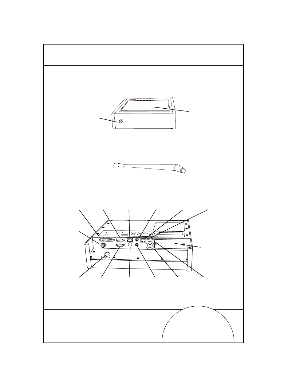
Parts of the VRC
3
LPT1
Parallel
Port
DC
PWR
Port
Reset
Switch
Antenna
Port
Serial Port
COM1
Serial
Port
COM2
Locking
Keyboard
Port
RF
Connection
Antenna
Keyboard
DIN
Connector
Mouse
Connector
Network
Connector
Audio
Indicator
Touchscreen
Speaker
PCMCIA
Card
Slot
Cover
Microphone
Port
Page 6

4
Set-Up
To set up your equipment, first unpack your terminal and
accessories, and ensure that the parts shipped match the parts
ordered. Keep the shipping container and packing material in
case you need to return your computer for repair at a later date.
The VRC is factory-equi pped with a network interfac e and the
appropriate network software for communicating with the
network. The network ports on the VRC use different connectors
for each type of ne twork. For Token Ring connections, a DB9
connector is used. For Ethernet connections, an RJ-45 connector
is used. For wireless network communications, an FCC
mandated, non-stand ard RF antenna connector is prov ided.
Note: The VRC 4040 uses Spectrum24 2.4 GHz spread-
spectrum radio link to communicate with (RF) network access points hard-wir ed into the LAN. These
access points must be set up before the terminal can
communicate with the host. Refer to the Access Point
User Documentation for detailed ins truc tions on se tting up the access points.
Mounting the Bracket Assemblies
The VRC 4000 can be mounted almost anywhere that is
convenient to the operator. The mounting location must be near
a standard 1 10 VAC electrical outlet, and there must be sufficient
space below the unit for cable access to the rear panel, which
faces downward when the unit is wall-mounted. Secure the
mounting bracket to a wall prior to attaching the VRC 4000 to
the bracket.
The VRC 4040 mounts to a forklift or other vehicle with a custom
bracket assembly. Operating power is obtained from a DC
power converter that attaches to the vehicle’s electrical system
Installation Guide
Page 7

via an access cord. Installation of the VRC 4040 requires
mounting the bracket assembly, installing the DC power
converter , and attaching the ac cess cord to the vehicle’s electrical
system.
Caution
For proper operation on electric fork lifts, the VRC must be
isolated from the chassis. Damage to terminal could result.
The three types of mounting bracket assemblies are:
• univers al mounting ass embly
• hyster mounting assembly
• crown mounting assembly.
Crown Mounting Assembly
The crown moun ting assembly has an L-shape d bra cket at the
top that permits mou nt ing of the assembly onto a flat vertical
wall or bracket. To mount the assembly:
5
Mounting Surface or
Bolt
Wall
Mounting Assembly
(without keyboard
assembly)
Nut
Page 8

6
1. Place the mounting assembly up against th e wall or
bracket. Make sure assembly is level.
2. Mark location for mounting holes.
3. Drill mounting holes using 13/32” drill bit.
4. Secure mounting bracket to wall using two bolts (3/8” x 16
x 3/4”) and two nuts.
5. Install VRC using procedure in VRC Mounting on page 8.
Universal Mounting Assembly
The universal mounting assembly has an U-shaped bracket at
the top that permits mounting of the assembly onto a horizontal
bracket. To mount the assembly:
Nut
Mounting
Bracket
U-Shaped
Bracket
Mounting
Assembly
(without
keyboard
assembly)
Bolt
1. Place the U-shaped bracket up against surface to use as a
template for drilling mountin g holes.
2. Mark location for mounting holes.
3. Drill two mounting holes using 13/32” drill bit.
4. Place bolts (3/8” x 20 x 3”) through the slots i n the assembly and through horizontal mounting bracket.
Installation Guide
Page 9

5. Place the U-shaped bracket over bolts and secure the U-
shaped bracket to th e assembly using two nuts.
6. Install VRC using procedures in VRC Mounting on pag e 8.
Hyster Mounting Assembly
The hyster mounting assembly has an L-shaped bracket at the
bottom that permit s mounting the bracket onto a flat vertical
wall or bracket. To mount the assembly:
Bracket
Assembly
(without
keyboard
assembly)
Nut
7
Bolt
Mounting Surface
or Wall
1. Place the assembly up against wall or bracket. Make sure
assembly is level.
2. Mark location for mounting holes.
3. Drill six mounting holes using 9/32” drill bit.
4. Secure assembly to wall or bracket using six bolts (1/4” x
20 x 3/4”) and six nuts.
5. Install VRC using procedures in VRC Mounting on pag e 8.
Page 10

8
VRC Mounting
After the mou nting bra cket is installed, m ount th e VRC on to the
assembly. To mount the VRC:
Bracket
Assembly
VRC
1. Align mounting holes on the sides of the VRC with the
holes on the arms of the mounting assembly.
2. Slide two rubber friction washers bet ween the mounti ng
assembly arms and the VRC. These washers must be
aligned with the mounting holes in the VRC and the
mounting assembly.
3. Insert the tw o knob scr ews thr ough the ho les in the mou nting assembly arms and into the mounting holes on the
VRC.
4. Position VRC at a desired viewing angle and turn knobs
clockwise to tighten.
5. Connect all required cables to the VRC.
Knob
Friction
Washer
Installation Guide
Page 11

Keyboard Assembly
The VRC mounting assembly may be configured with or
without the keyboard assembly. If the keyboard assembly is not
originally configur ed, it can be ad ded to the mounting a ssembly
at a later time. To mount the keyboard assembly onto the
mounting bracket assembly:
Bracket
Assembly
Nut
Keyboard
Assembly
Bolt
9
1. Remove power from the VRC.
2. Disconnect all cables connected to the VRC.
3. Remove two knob screws securing the VRC and rubber
friction washers to the mounting brack et assembly.
4. Align mounting wings of keyboard assembly with mount-
ing wings of mounting bracket.
Page 12

10
5. Insert eight bolts, supplied with the keyboard assembly,
through mounting holes in mounting bracket an d keyboard assembly bracket.
6. Secure bolts using eight nuts.
7. Install VRC using procedures in VRC Mounting on page 8.
8. Connect keyboard cable to connector on rear panel of VRC.
Note: The Symbol-supplied ruggedized keyboard has a
special locking connector which is designed to ensure good cont ac t in the high-vibration veh ic l e
mount application.
9. If a scanner is at tached to the VRC, a spec ial “Y” cable
(P/N STI180-0275) is required to connect the keyboard and
scanner to the keyboard connector on the r ear panel:
a. Connect the keyboard connector to the mating connec-
tor on the special cable.
b. Connect the scanner connector to the mating connector
on the special cable.
c. Connect the special cable to the keyboard connector on
the rear panel of the VRC.
10. Connect all cables removed in step 2.
11. Apply power to the VRC.
Installation Guide
Page 13

Providing Power to the VRC 4000
Power is provided to the VRC 4000 terminal via a locking DCpower adapter, as illustrated below:
All cable connections should be made to the VRC 4000 before
the system is powered up. Since ther e is no ON/OFF sw itch, the
VRC 4000 powers up as soon as the power supply connections
are completed and the power supply is plugged in to the 110
VAC electrical outlet.
Providing Power to the VRC 4040
Power is provided to the VRC 4040 via a DC power converter (12
V or 24-48V) that is connected to the vehicle’s battery. The DC
power converter mounts to a steel surface on the vehicle via
magnetic feet. Locate the converter so as not to interfere with
either moving parts on the vehicle or the operator’s vision. Be
certain that the power cable from the DC power converter can
reach the mating co nnector on the VRC 4 040.
The access cable should be connected to the vehicle’s electrical
system, at the point that provides power at all times and that is
11
Page 14

12
filtered and fu sed. Never c onnect the access cable dir ectly t o the
battery terminals. Possible connection points are at the horn,
lights (feed), or ignition switch (feed).
24-48 V Power Converter
The electrical harness access cable for the 24-48 V Power
converter has two leads at one end which are permanently
wired into the vehicle’s electrical system. The other end of the
cable has a circular 2-pin connector with rubber boot that mates
with a similar connector on the DC power converter’s power
input cable.
Caution
On some older electric fork lifts, it might be necessary to install a 4 amp, 25 mhy f ilter choke (STANCOR p/n C-2686
or equivalent) in series with the positive lead to prevent
motor transients from interfering with the terminal.
The black harness wir e is con nected to a positive voltage source .
The white harness wire is connected to the negative voltage
source. The booted connector end of the cable should be
accessible for conveni ent atta chment to th e DC power conv erter.
Make sure that the DC power converter ON/OFF switch is in
the OFF position. Once the access cable is wir ed to the electr ical
system, mate the connectors on the access cable and the DC
power converter power input cable. All cable connections must
be completed before applying power to the VRC 4040.
12 V Power Converter
The electrical harness access cable fo r t he 12 V pow er conve rter
has three leads at one en d which are perma nently wir ed into the
vehicle’s electrical system. The leads ar e white and black, plus a
third lead that is either shield braid or green. The other end of
the cable has a circular 3-pin connector with rubber boot that
Installation Guide
Page 15

mates with a sim il ar connector on the DC power converter’s
power input cable.
The black harness wire is c onnected to a positive volta ge source.
The white harness wire is connected to a negative voltage
source. The green or braided lead is connected to chassis
ground. The booted connector end of the cable should be
accessible for conveni ent attac hment to th e DC power co nverter.
Make sure the DC power converter ON/OFF switch is in the
OFF position. Once the access cable is wired to the electrical
system, mate the connectors on the access cable and the DC
power converter power input cable. All cable connections must
be completed before applying power to the VRC 4040.
Maintenance
The VRC is designed to operate normally in industrial
environments which may contain high levels of airborne
contaminants inclu ding dirt and s moke. Periodic cle aning of the
VRC is recommended to r emove bu ild-up of for eign sub stances
on the case and touchscreen.
Before cleaning, remove power from the VRC. Wipe
accumulated dirt and dust from the case with a slightly
dampened cloth, paying particular attention t o the ang led edge
of the bezel. Clean the touchscreen with a commercial brand of
computer screen cleaner and a soft, damp cloth or compressed
air.
13
Page 16

14
Regulatory Information
Labeling
Symbol T echnologies, Inc.
Holtsville, NY
(1P) Model:
VRC4040-10C40DUS
Net ID: 00A0F8166421
(S) S/N:
This device complies with Part 15 of the FCC Rules.Operation is subject to the
following two conditions: (1)This device may not cause harmful interference, and
(2)This device must accept any interference received, including interference that
may cause undesired operation. This Class A digital apparatus meets all
requirements of the Canadian Interference-causing Equipment Regulations. CET
appareil Numerique de la classe a respecte toutes les exigences du reglement sur
le materiel brouilleur du Canada.
Y463732
INDUSTRIAL COMPUTER
16WA
LISTED I.T.E. 12 VDC @ 2.5A
3897
Made in USA
Installation Guide
Page 17

Radio Frequency Interference Requirements
This device has been tested and found to comply with the limits for a Class A
digital device pursuant to Part 15 of the Federal Communications Commissions
Rules and Regulation. These limits are designed to provide reasonable protection
against harmful interference when the equipment is operated in a commercial
environment. This equipment generates, uses, and can radiate radio frequency
energy and, if not installed and used in accordance with the instruction manual,
may cause harmful interference to radio communications. Operation of this
equipment in a residential area is likely to cause harmful interfer ence in which case
the user will be required to correct the interference at his own expense.
However, there is no guarantee that interference will not occur in a particular
installation. If the equipment does cause harmful interfer ence to radio or televis ion
reception, which can be determined by turning the e quipment of f and on, the user
is encouraged to try to correct the interference by one or more of the following
measures:
• Re-orient or relocate the receiving antenna.
• Increase the separation between the equipment and receiver.
• Connect the e quipment into an outlet on a circuit different from that which
the receiver is connected.
• Consult the dealer or an experienced radio/TV technician for help.
Radio Frequency Interfer ence Requirements
- Canada
This Class A digital apparatus meets the requirements of the Canadian
Interference-Causing Equipment Regulations.
Cet appareil numérique de la Classe A r espe cte toutes le s exigences du Reglem ent
sur le Materiél Brouilleur du Canada.
15
Page 18

16
CE Marking and European Union Compliance
Products intended for sale within the European Union are marked
with the CE Mark which indicates compliance to applicable
Directives and European Normes (EN), as follows. Amendments to
these Directives or ENs are included:
Applicable Directives
• Electromagnetic Compatibility Directive 89/336/EEC
• Low Voltage Directive 73/23/EEC
Applicable Standards
• EN 55 022 - Limits and Methods of Measurement of Radio Interference
Characteristics of Information technology Equipment
• EN 50 082-1 - Electromagnetic Compatibility - Generic Immunity Standard,
Part 1: Residential, commercial, Light Industry
• IEC 801.2 - Electromagnetic Compatibility for Industrial Process Measurement and Control Equipment Part 2: Electrostatic Discharge Requirements
• IEC 801.3 - Electr omagnetic Compatibility for Industrial Process Measurement and Contr o l Equipment Part 3: Radiat e d Electromagnetic F i eld Requirements
• IEC 801.4 - Electromagnetic Compatibility for Industrial Process Measurement and Control Equipment Part 4: Electrical Fast Transients Requir ements
• EN 60 950 + Amd 1 + Amd 2 - Safety of Information Technology Equipment
Including Elect r ical Business Equipment
• EN 60 825-1 (EN 60 825) - Safety of Devices Containing Lasers
RF Devices
Symbol’s RF products are designed to be compliant w ith the rules and r egulations
in the locations into which they are sold and will be labeled as required. The
majority of Symbol’s RF devices are type approved and do not require the user to
obtain license or authorization before using the equipment. Any changes or
modifications to Symbol Technologies equipment not expressly approved by
Symbol Technologies could void the user’s authority to operate the equipment.
Installation Guide
Page 19

Related Publications
• Spectrum24 Ethernet Access Point User Guide,
p/n 70-12057-XX
• Spectrum24 Ethernet Access Point User Guide Addendum,
p/n 70-12057-XX
• VRC 4000 Product Reference Guide,
p/n 70-19725-XX
Warranty Information
For Warranty & Service Information, Call:
1-800-653-5350
Outside Nort h America, contact your local Symbol
representative
Symbol products are warranted against defects in workmanship and materials for
a period of one year (unless specified otherwise) from the date of shipment,
provided that the product rema ins unmodified and is ope rated under normal and
proper conditions.
This warranty is limited to repair or replacement at Symbol’s option, with
reasonable promptness after being returned to Symbol by a carrier selected and
paid for by the customer. These provisions do not prolong the original warranty
term for any product which has been repaired or replaced by Symbol.
This warranty applies to the original owner and does not extend to any product
which has been subject to misuse, neglect, accidental damage, unauthorized repair
or tampering. Preventive maintenance activities are not covered by warranty.
17
Page 20

This product is covered by one or more of the following U.S. and foreign Patents:
U.S. Patent No. 4,360,798; 4,369,361; 4,387,297; 4,460,120; 4,496,831; 4,593,186;
4,603,262; 4,607,156; 4,652,750; 4,673,805; 4,736,095; 4,758,717; 4,816,660; 4,845,350;
4,896,026; 4,897,532; 4,923,281; 4,933,538; 4,992,717; 5,015,833; 5,017,765; 5,021,641;
5,029,183; 5,047,617; 5,103,461; 5,113,445; 5,130,520; 5,140,144; 5,142,550; 5,149,950;
5,157,687; 5,168,148; 5,168,149; 5,180,904; 5,229,591; 5,230,088; 5,235,167; 5,243,655;
5,247,162; 5,250,791; 5,250,792; 5,262,627; 5,262,628; 5,280,163; 5,280,164; 5,280,498;
5,304,786; 5,304,788; 5,321,246; 5,377,361; 5,367,151; 5,373,148; 5,378,882; 5,396,053;
5,396,055; 5,399,846; 5,408,081; 5,410,139; 5,410,140; 5,412,198; 5,418,812; 5,420,411;
5,436,440; 5,444,231; 5,449,891; 5,449,893; 5,468,949; 5,479,000; 5,479,002; 5,479,441;
5,504,322; 5,528,621; 5,532,469; 5,543,610; 5,545,889; 5,552,592; 5,578,810; 5,589,680;
5,608,202; 5,612,531; 5,619,028; D305,885; D341,584; D344,501; D359,483; D362,453;
D363,700; D363,918; D370,478.
Invention No. 55,358; 62,539; 69,060; 69,187 (Taiwan); No. 1,601,796; 1,907,875;
1,955,269 (Japan).
European Patent 367,299; 414,281; 367,300; 367,298; UK 2,072,832; France 81/03938;
Italy 1,138,713.
Revision A — September 1997
70-32536-01
 Loading...