

Page 1
MC70 Enterprise Digital Assistant
User Guide
Page 2

Page 3

MC70
User Guide
72E-71769-01
Revision B
August 2006
Page 4

ii MC70 User Guide
© 2006 by Symbol Technologies, Inc. All rights reserved.
No part of this publication may be reproduced or used in any form, or by any electrical or mechanical means,
without permission in writing from Symbol. This includes electronic or mechanical means, such as
photocopying, recording, or information storage and retrieval systems. The material in this manual is subject to
change without notice.
The software is provided strictly on an “as i s” basis. All sof twar e, including firmware, furnished to the user is on
a licensed basis. Symbol grants to the user a non-tran sferable an d non-exclusive license to use each sof tware
or firmware program delivered hereunder (licensed program) . Except as n oted below, such license may not be
assigned, sublicensed, or otherwise transferred by th e user without pr ior written consent of Symbo l. No right to
copy a licensed program in whole or in part is granted, exce pt as permitted unde r copyright law. The user shall
not modify , merge, or incorporate any for m or portion of a licensed program with other pro gram material, create
a derivative work from a licensed program , or us e a li censed program in a network without written permission
from Symbol. The user agrees to maintain Symbol’s copyright notice on the licensed programs delivered
hereunder , and to include the same on any authorized copies it makes, in whole or in part. The user agrees not
to decompile, disassemble, decode, or reverse engineer any licensed program delivered to the user or any
portion thereof.
Symbol reserves the right to make changes to any software or product to improve reliability , function, or design.
Symbol does not assume any product liability arising out of, or in connection with, the application or use of any
product, circuit, or application described herein.
No license is granted, either expressly or by implication, estoppel, or otherwise under any Symbol
Technologies, Inc., intellectual property rights. An implied license only exists for equipment, circuits, and
subsystems contained in Symbol products.
Symbol and the SYmbol logo are registered trademarks of Symbo l Technologies, In c. Bluetooth is a registered
trademark of Bluetooth SIG. Microsoft, Windows and ActiveSync are either registered trademarks or
trademarks of Microsoft Corporation. Other product names mentioned in this manual may be trademarks or
registered trademarks of their respective companies and are hereby acknowledge d.
Symbol Technologies, Inc.
One Symbol Plaza
Holtsville, New York 11742-1300
http://www.symbol.com
Patents
This product is covered by one or more of the patents listed on the website: www.symbol.com/patents
Page 5

Revision History
Changes to the original manual are listed below:
Change Date Description
A 1/2006 Initial release.
B 8/2006 Add Revision History page.
iii
Chapter 2:
Add vibrator feature information.
Remove Green and Red Phone button remapping information. Not supported.
Update cold boot procedure to remove step to calibrate screen after cold boot.
Page 6

iv MC70 User Guide
Page 7

Table of Contents
Patents........................................................................................................................... ii
Revision History............................................................................................................. iii
About This Guide
Introduction.................................................................................................................... xi
Documentation Set .................................................................................................. xi
Configurations................................................................................................................ xii
Chapter Descriptions ..................................................................................................... xiii
Notational Conventions.................................................................................................. xiii
Related Documents ....................................................................................................... xiv
Service Information........................................................................................................ xiv
Symbol Support Center............................................................................................ xiv
Chapter 1: Getting Started
Introduction ................................................................................................................... 1-1
Unpacking ..................................................................................................................... 1-2
Accessories ................................................................................................................... 1-3
Getting Started .............................................................................................................. 1-4
Installing and Removing the Main Battery .................................................................... 1-4
Installing the Main Battery ....................................................................................... 1-4
Removing the Main Battery ..................................................................................... 1-5
Charging the Battery ..................................................................................................... 1-6
Charging the Main Battery and Memory Backup Battery ........................................ 1-6
Charging Spare Batteries ........................................................................................ 1-7
Charging Temperature ............................................................................................ 1-8
Powering On the EDA ................................................................................................... 1-8
Calibrating the Screen ............................................................................................ 1-8
Checking Battery Status ............................................................................................... 1-8
SIM Card ....................................................................................................................... 1-9
Adjusting the Handstrap ................................................................................................ 1-10
Removing the Screen Protector .................................................................................... 1-11
Battery Management ..................................................................................................... 1-11
Changing the Power Settings ................................................................................. 1-12
Changing the Backlight Settings ............................................................................. 1-12
Changing the Keypad Backlight Settings ................................................................ 1-12
Turning Off the Radios ............................................................................................ 1-12
Page 8

vi MC70 User Guide
Turning Off the WLAN Radio ............................................................................ 1-12
Turning Off the Bluetooth and WAN Radios ..................................................... 1-13
Chapter 2: Using the MC70
Introduction ................................................................................................................... 2-1
Status Icons .................................................................................................................. 2-1
Speaker Icon ........................................................................................................... 2-3
Battery Icon ............................................................................................................. 2-4
Connectivity Icon ..................................................................................................... 2-4
WWAN Icon ............................................................................................................ 2-5
Time Icon ................................................................................................................ 2-5
Instant Message Icon .............................................................................................. 2-6
E-Mail Icon .............................................................................................................. 2-7
Multiple Notifications Icon ....................................................................................... 2-7
LED Indicators .............................................................................................................. 2-8
Keypads ........................................................................................................................ 2-9
Numeric Keypad Configuration ............................................................................... 2-9
QWERTY Keypad Configuration ............................................................................. 2-13
Special Character Key ...................................................................................... 2-17
Function Buttons ........................................................................................................... 2-19
Stylus ............................................................................................................................ 2-19
Using a Headset ........................................................................................................... 2-20
Data Capture ................................................................................................................ 2-20
Linear Scanning ...................................................................................................... 2-21
Imaging ................................................................................................................... 2-21
Operational Modes ............................................................................................ 2-21
Scanning Considerations ........................................................................................ 2-21
Linear Scanning ...................................................................................................... 2-22
Imager Scanning ..................................................................................................... 2-23
Resetting the EDA ........................................................................................................ 2-24
Performing a Warm Boot ........................................................................................ 2-24
Performing a Cold Boot ........................................................................................... 2-24
Waking the EDA ...................................................................................................... 2-25
Locking the EDA ........................................................................................................... 2-25
Chapter 3: Using Bluetooth
Introduction ................................................................................................................... 3-1
Adaptive Frequency Hopping ....................................................................................... 3-1
Security ......................................................................................................................... 3-2
Turning the Bluetooth Radio Mode On and Off ............................................................ 3-2
Disabling Bluetooth ................................................................................................. 3-3
Enabling Bluetooth .................................................................................................. 3-3
Bluetooth Power States .......................................................................................... 3-3
Cold Boot .......................................................................................................... 3-3
Warm Boot ........................................................................................................ 3-4
Suspend ............................................................................................................ 3-4
Resume ............................................................................................................. 3-4
Page 9

Table of Contents - vii
Modes ........................................................................................................................... 3-4
Wizard Mode ........................................................................................................... 3-4
Explorer Mode ......................................................................................................... 3-6
Discovering Bluetooth Device(s) ................................................................................... 3-7
Bonding with Discovered Device(s) .................................................................. 3-8
Renaming a Bonded Device ............................................................................. 3-10
Deleting a Bonded Device ................................................................................. 3-11
Accepting a Bond .............................................................................................. 3-12
Discovering Services .................................................................................................... 3-12
File Transfer Services ............................................................................................. 3-13
Creating a New File or Folder ........................................................................... 3-14
Deleting a File ................................................................................................... 3-14
Getting a File ..................................................................................................... 3-14
Copying a File ................................................................................................... 3-15
Connecting to the Internet Using an Access Point .................................................. 3-15
Dial-Up Networking Services .................................................................................. 3-15
Adding a Dial-up Entry ...................................................................................... 3-18
Object Exchange Push Services ............................................................................. 3-19
Sending a Contact ............................................................................................. 3-19
Sending a Picture .............................................................................................. 3-20
Headset Services .................................................................................................... 3-21
Serial Port Services ................................................................................................ 3-22
ActiveSync Using Serial Port Services .............................................................. 3-23
Personal Area Network Services ............................................................................ 3-24
Bluetooth Settings ......................................................................................................... 3-25
Device Info Tab ....................................................................................................... 3-25
Services Tab ........................................................................................................... 3-25
Dial-Up Networking Service .............................................................................. 3-26
File Transfer Service ......................................................................................... 3-27
Hands-Free Service .......................................................................................... 3-27
Headset Service ................................................................................................ 3-28
OBEX Object Push Service ............................................................................... 3-28
Personal Area Networking Service ................................................................... 3-29
Serial Port Service ............................................................................................ 3-29
Security Tab ............................................................................................................ 3-30
Discovery Tab ......................................................................................................... 3-31
Virtual COM Port Tab .............................................................................................. 3-31
Miscellaneous Tab .................................................................................................. 3-32
Chapter 4: Using the MC7004/MC7094 Phone
Introduction ................................................................................................................... 4-1
Accessing the Phone Keypad ....................................................................................... 4-1
Making a Call Using the Keypad ............................................................................. 4-2
Turning the Phone On and Off (Flight Mode) ................................................................ 4-2
Answering a Call ........................................................................................................... 4-3
Audio Modes ........................................................................................................... 4-3
Incoming Call Features ........................................................................................... 4-4
Muting a Call ................................................................................................................. 4-4
Page 10

viii MC70 User Guide
Taking Notes ................................................................................................................. 4-5
Using Speed Dial .......................................................................................................... 4-6
Adding a Speed Dial Entry ...................................................................................... 4-6
Editing a Speed Dial Entry ...................................................................................... 4-8
Deleting a Speed Dial Entry .................................................................................... 4-9
Making a Speed Dial Call ........................................................................................ 4-10
Using Call History ......................................................................................................... 4-11
Managing Call History ............................................................................................. 4-12
Changing the Call History View ........................................................................ 4-12
Resetting the Recent Calls Counter .................................................................. 4-12
Deleting Call History Items by Call Date ........................................................... 4-13
Deleting All Call History Items ........................................................................... 4-14
Viewing Call Status ........................................................................................... 4-14
Using the Call History Menu ............................................................................. 4-15
Using Contacts ............................................................................................................. 4-16
Swapping Calls ............................................................................................................. 4-16
Conference Calling ....................................................................................................... 4-17
Text Messaging ............................................................................................................ 4-18
Sending a Message ................................................................................................ 4-18
Chapter 5: Accessories
Introduction ................................................................................................................... 5-1
Cables ..................................................................................................................... 5-1
Cradles .................................................................................................................... 5-1
Miscellaneous ......................................................................................................... 5-1
Snap-on Modules .................................................................................................... 5-1
Headset ........................................................................................................................ 5-2
Multi Media Card (MMC) / Secure Digital (SD) Card .................................................... 5-2
Single Slot USB/Serial Cradle ...................................................................................... 5-3
Charging the EDA Battery ....................................................................................... 5-4
Charging the Spare Battery .................................................................................... 5-4
Battery Charging Indicators .................................................................................... 5-5
Charging Temperature ...................................................................................... 5-5
Four Slot Ethernet Cradle ............................................................................................. 5-5
Charging ................................................................................................................ 5-6
Battery Charging Indicators .................................................................................... 5-6
Charging Temperature ...................................................................................... 5-6
VCD7000 Vehicle Cradle .............................................................................................. 5-7
Charging the EDA Battery ....................................................................................... 5-7
Removing the EDA ........................................................................................... 5-8
Charging the Spare Battery .................................................................................... 5-8
Battery Charging Indicators .................................................................................... 5-9
Charging Temperature ...................................................................................... 5-9
Four Slot Spare Battery Charger .................................................................................. 5-10
MC70 Battery Shim Installation ............................................................................... 5-10
Spare Battery Charging .......................................................................................... 5-11
Battery Charging Indicators .................................................................................... 5-11
Charging Temperature ...................................................................................... 5-11
Page 11

Magnetic Stripe Reader (MSR) ..................................................................................... 5-12
Attaching and Removing the MSR .......................................................................... 5-12
Using the MSR ....................................................................................................... 5-13
TRG7000 Trigger Handle .............................................................................................. 5-13
Inserting the EDA into the Trigger Handle .............................................................. 5-14
Removing the EDA ................................................................................................. 5-14
Scanning ................................................................................................................. 5-14
Using a Cradle ........................................................................................................ 5-15
Cables ........................................................................................................................... 5-16
Battery Charging and Operating Power .................................................................. 5-17
LED Charge Indications .......................................................................................... 5-17
Charging Temperature ...................................................................................... 5-17
Chapter 6: Maintenance & Troubleshooting
Introduction ................................................................................................................... 6-1
Maintaining the EDA ..................................................................................................... 6-1
Troubleshooting ............................................................................................................ 6-2
EDA ......................................................................................................................... 6-2
Bluetooth Connection .............................................................................................. 6-4
Single Slot USB/Serial Cradle ................................................................................. 6-6
Four Slot Ethernet Cradle ....................................................................................... 6-7
Vehicle Cradle ......................................................................................................... 6-8
Four Slot Spare Battery Charger ............................................................................ 6-8
Cables ..................................................................................................................... 6-9
Magnetic Stripe Reader .......................................................................................... 6-9
Trigger Handle .............................................................................................................. 6-10
Table of Contents - ix
Appendix A: Technical Specifications
MC70 Technical Specifications ..................................................................................... A-1
MC70 Accessory Specifications .................................................................................... A-4
Page 12

x MC70 User Guide
Page 13

About This Guide
Introduction
This guide provides information about using the MC7 0 Ent er pri se Digital Assistant (EDA) and acces sor ie s.
NOTE Screens and windows pictured in this guide are samples and can differ from actual screens.
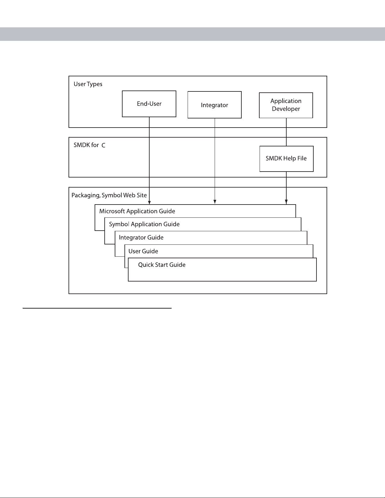
Documentation Set
The documentation set for the MC70 provides information for specific user needs, and includes:
•
Microsoft® Windows Mobile 5.0 Applications User Guide for Symbol Devices - describes how to
use Microsoft developed applications.
About This Guide
•
Symbol Application Guide - describes how to use Symbol developed sample applications.
•
MC70 User Guide - describes how to use the MC70 EDA.
•
MC70 Integrator Guide - describes how to set up the MC70 EDA and accessories.
•
SMDK Help File - provides API information for writing applications.
Page 14
xii MC70 User Guide
Configurations
This guide covers the following configurations:
•
MC7004 - Windows® Mobile 5.0 Operating System; EDGE GPRS quad-band WAN radio; Bluetooth®
wireless technology (Class II); QVGA 3.5” color display; 64MB RAM/128MB flash memory; 1D laser
scanner or 2D imager; numeric or QWERTY keyp ad; VoIP ready (VoIP application does not sh ip with the
EDA); user accessible SD card slot.
•
MC7090 - Windows® Mobile 5.0 Operating System; 802.11a/b/g radio; Bluetooth® wireless technology;
color display; 64MB RAM/128MB flash memory; 1D laser scanner or 2D imager; numeric or QWERTY
keypad; VoIP ready (VoIP application does not ship with the EDA); user accessible SD card slot.
•
MC7094 - Windows® Mobile 5.0 Operating System; 802.11a/b/g radio; GPRS WAN radio; Bluetooth®
wireless technology; color display; 64MB RAM/128MB flash memory; 1D laser scanner or 2D imager;
numeric or QWERTY keypad; VoIP ready (VoIP application does not ship with the EDA); user accessib le
SD card slot.
Page 15

Chapter Descriptions
Topics covered in this guide are as follows:
•
Chapter 1, Getting Started provides information on getting the EDA up and running for the first time.
•
Chapter 2, Using the MC70 provides basic instructions for using the EDA, including powering on and
resetting the EDA, and entering and capturing data.
•
Chapter 3, Using Bluetooth explains Bluetooth functionality on the EDA.
•
Chapter 4, Using the MC7004/MC7094 Phone provides basic instructions for using the MC70 phone.
•
Chapter 5, Accessories describes the available accessories and how to use them with the EDA.
•
Chapter 6, Maintenance & Troubleshooting includes instructions on cleaning and storing the EDA, and
provides troubleshooting solutions for potential problems during EDA operation.
•
Appendix A, Technical Specifications provides the technical specifications for the EDA.
Notational Conventions
About This Guide xiii
The following conventions are used in this document:
•
“EDA” refers to the Symbol MC70 series of hand-held EDAs.
•
Italics are used to highlight the following:
- Chapters and sections in this and related documents
- Dialog box, window, and screen names
- Drop-down list and list box names
- Check box and radio button names
- Icons on a screen.
•
Bold text is used to highlight the following:
- Key names on a keypad
- Button names on a screen.
•
bullets (•) indicate:
- Action items
- Lists of alternatives
- Lists of required steps that are not necessarily sequential
•
Sequential lists (e.g., those that describe step-by-step procedures) appear as numbered lists.
Page 16

xiv MC70 User Guide
Related Documents
•
MC70 Quick Star t Guide, p/n 72-71770-xx
•
MC70 Microsoft Mobile 5.0 Regulatory Information, p/n 72-71767-xx
•
MC70 Integrator Guide, p/n 72E-71768-xx
•
Microsoft® Applications for Mobile and CE 5.0 User Guide, p/n 72E-78456-xx
•
Symbol Application Guide, p/n 72E-68901-xx
•
Symbol Mobility Developer Kits (SMDKs), available at: http://devzone.symbol.com/.
•
Latest ActiveSync software, available at: http://www.microsoft.com.
For the latest version of this guide and all guides, go to: http://www.symbol.com/mc70.
Service Information
If you have a problem with your equipment, contact the “Symbol Support Center,” for your region. See page
xiv for contact information. Before calling, have the model number, serial number , and several of your bar code
symbols at hand.
Call the Support Center from a phone near the scanning equipment so that the service person can try to talk
you through your problem. If the equipment is found to be working properly and the problem is symbol
readability, the Support Center will request samples of your bar codes for analysis at our plant.
If your problem cannot be solved over the phone, you may need to return your equipment for servicing. If that
is necessary, you will be given specific directions.
Symbol Technologies is not responsible for any damages incurred during shipment if the app roved shipping
container is not used. Shipping the units improperly can possibly void the warranty. If the original shipping
container was not kept, contact Symbol to have another sent to you.
Symbol Support Center
For service information, warranty information or technical assistance contact or call the Symbol Support Center
in:
Country/Region Address Telephone
United States Symbol Technologies, Inc.
One Symbol Plaza
Holtsville, New York 11742-1300
Canada Symbol Technologies Canada, Inc.
5180 Orbitor Drive
Mississauga, Ontario, Canada L4W 5L9
1-800-653-5350
1-866-416-8545 (Inside Canada)
905-629-7226 (Outside Canada)
United Kingdom Symbol Technologies
Symbol Place
Winnersh Triangle, Berkshi re RG41 5TP
United Kingdom
0800 328 2424 (Inside UK)
+44 118 945 752 9 (O utside UK)
Page 17

About This Guide xv
Country/Region Address Telephone
Asia/Pacific Symbol Technologies Asia, Inc.
(Singapore Branch)
230 Victoria Street #12-06/10
Bugis Junction Office To wer
Singapore 188024
Australia Symbol Technologies Pty. Ltd.
432 St. Kilda Road
Melbourne, Victoria 3004
Australia
Austria/Österreich Symbol Technologies Austria GmbH
Prinz-Eugen Strasse 70 / 2.Haus
1040 Vienna, Austria
01-5055794-0 (Inside Austria)
Denmark/Danmark Symbol Technologies AS
Dr. Neergaardsvej 3
2970 Hørsholm, Denmark
Europe/Mid-East
Distributor
Operations
Finland/Suomi Oy Symbol Technologies
Kaupintie 8 A 6
FIN-00440 Helsinki, Finland
Tel: +65-6796-9600
Fax: +65-6337-6488
1-800-672-906 (Inside Australia)
+61-3-9866-6044 (Outside Australia
+43-1-5055794-0 (Outside Austria)
7020-1718 (Inside Denmark)
+45-7020-1718 (Outside Denmark)
Contact your local distributor or call +44 118
945 7360
9 5407 580 (Inside Finland)
+358 9 5407 580 (Outside Finland)
France Symbol Technologies France
Centre d'Affaire d'Antony
3 Rue de la Renaissance
92184 Antony Cedex, France
Germany/
Deutschland
Italy/Italia Symbol Technologies Italia S.R.L.
Latin America
Sales Support
Mexico/México Symbol Technologies Mexico Ltd.
Netherlands/Neder
land
Symbol Technologies GmbH
Waldstrasse 66
D-63128 Dietzenbach, Germany
Via Cristoforo Columbo, 49
20090 Trezzano S/N Navigilo
Milano, Italy
2730 University Dr.
Coral Springs, FL 33065 USA
Torre Picasso
Boulevard Manuel Avila Camacho No
88
Lomas de Chapultepec CP 11000
Mexico City, DF, Mexico
Symbol Technologies
Kerkplein 2, 7051 CX
Postbus 24 7050 AA
Varsseveld, Netherlands
01-40-96-52-21 (Inside France)
+33-1-40-96-52-50 (Outside France)
6074-49020 (Inside Germany)
+49-6074-49020 (Outside Germany)
2-484441 (Inside Italy)
+39-02-484441 (Outside Italy)
1-800-347-0178 (Inside United States)
+1-954-255-2610 (Outside United States)
954-340-9454 (Fax)
5-520-1835 (Inside Mexico)
+52-5-520-1835 (Outside Mexico)
315-271700 (Inside Netherlands)
+31-315-271700 (Outside Netherlands)
Page 18

xvi MC70 User Guide
Country/Region Address Telephone
Norway/Norge Symbol’s registered and mailing
address:
Symbol Technologies Norway
Hoybratenveien 35 C
N-1055 OSLO, Norway
Symbol’s repair depot and shipping
address:
Symbol Technologies Norway
Enebakkveien 123
N-0680 OSLO, Norway
South Africa Symbol Technologies Africa Inc.
Block B2
Rutherford Estate
1 Scott Street
Waverly 2090 Johannesburg
Republic of South Africa
Spain/España Symbol Technologies S.L.
Avenida de Bruselas, 22
Edificio Sauce
Alcobendas, Madrid 28108
Spain
Sweden/Sverige “Letter” address:
Symbol Technologies AB
Box 1354
S-171 26 SOLNA
Sweden
+47 2232 4375
11-809 5311 (Inside South Africa)
+27-11-809 5311 (Outside South Africa)
91 324 40 00 (Inside Spain)
+34 91 324 40 00 (Outside Spain)
Fax: +34.91.324.4010
Switchboard: 08 445 29 00 (domestic)
Call Center: +46 8 445 29 29 (international)
Support E-Mail:
Sweden.Support@se.symbol.com
Visit/shipping address:
Symbol Technologies AB
Solna Strandväg 78
S-171 54 SOLNA
Sweden
If you purchased your Symbol product from a Symb ol Bus ine ss Par tn er, contact that Business Partner for
service.
For the latest version of this guide go to:http://www.symbol.com/manuals.
Page 19
Chapter 1 Getting Started
Introduction
This chapter lists the parts and accessories for the EDA and explains how to install and charge the batteries,
replace the strap, and power on the EDA for the first time.
Chapter 1
Getting Started
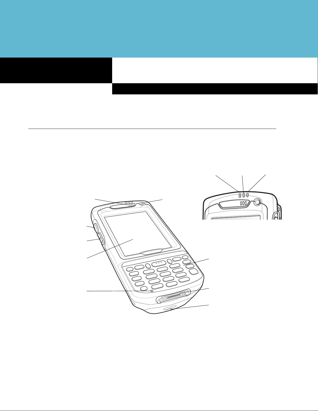
Receiver
Scan/Action Button
Up/Down Button
Touch Screen with
Protective Overlay
Microphone
Power Button
Scan/Decode
LED
Keypad
(Numeric Keypad Pictured)
I/O Connector
Handstrap Attachment
Charge
Status LED
Radio Power
Status LED
Figure 1-1
MC70 Front View
Page 20
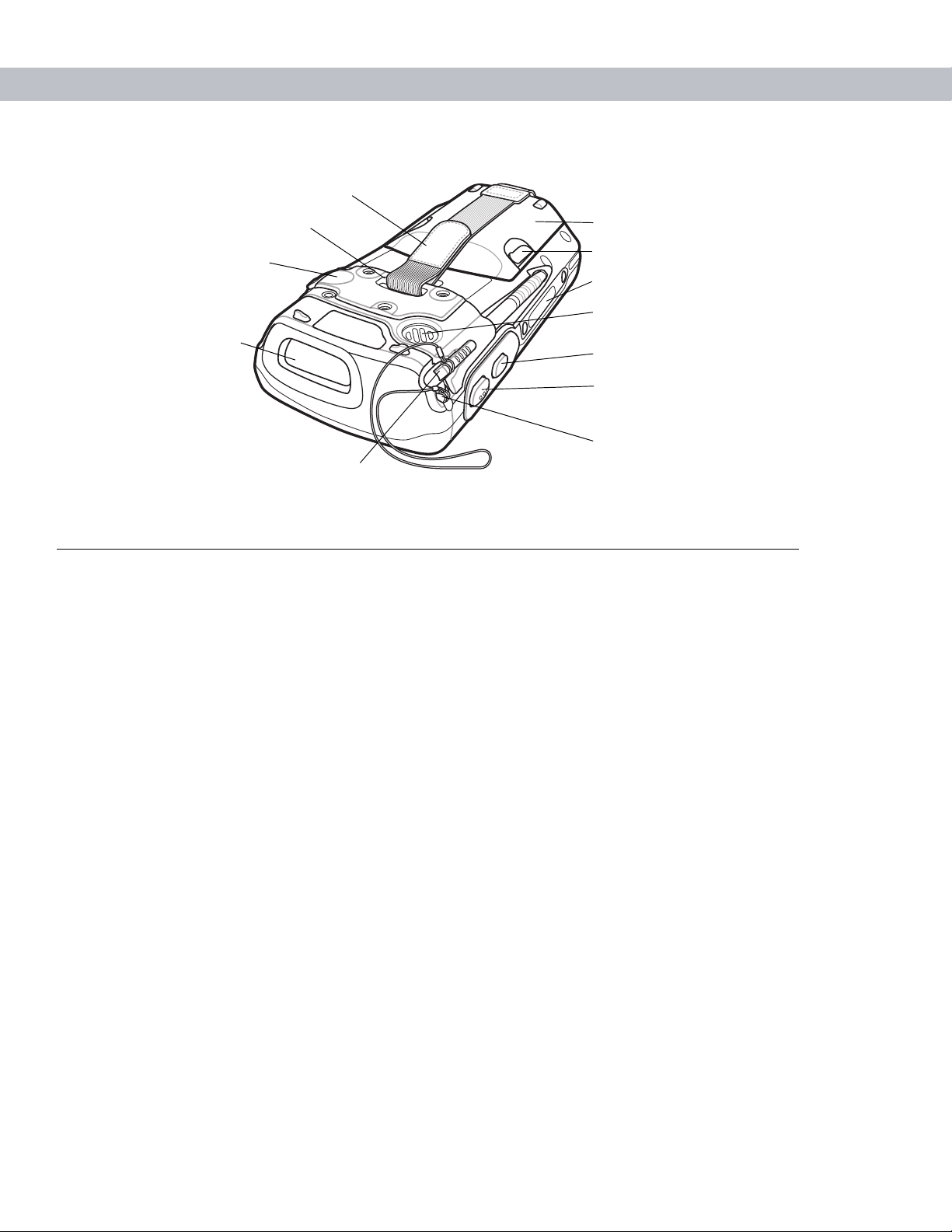
1 - 2 MC70 User Guide
Handstrap Slot
Headset Jack
Handstrap
Battery Cover
Battery Cover Latch
Memory Card Slot
Speaker
(Imager Model Shown)
Figure 1-2
Unpacking
Carefully remove all protective material from the EDA and save the shipping container for later storage and
shipping.
Verify that you received the following equipment:
•
MC70 EDA
•
Lithium-ion battery
•
Battery cover/strap assembly
•
Tethered stylus
Scan Window
Action Button
Scan/Action Button
Tether Point
Stylus
MC70 Rear View
•
Protective overlay, installed on display window
•
Regulatory Guide
•
Quick Start Guide.
Inspect the equipment for damage. If any equipment is missing or damaged, contact the Symbol Technologies
Support Center immediately. See page xiv for contact information.
Page 21

Accessories
Table 1-1 lists the accessories available for the MC70 EDA.
Getting Started 1 - 3
Table 1-1
MC70 Accessories
Accessory Description
Snap-on Cables The EDA supports the following cables:
•
AC line cord (country-specific) and power supply, charges the EDA.
•
Auto charge cable, charges the EDA using a vehicle’s cigarette lighter.
•
DEX cable, connects the EDA to a vending machine.
•
Serial cable, adds serial communication capabilities.
•
USB cable, adds USB communication capabilities.
•
Modem inverter cable.
•
Printer cables, available for O’Neil and Zebra printers from printer
vendors.
Single Slot USB/Serial
Cradle
Charges the EDA main battery and a spare battery. Synchronizes the EDA with
a host computer through either a serial or a USB connection.
Four Slot Ethernet Cradle Charges the EDA main battery and connects the EDA with an Ethe rnet network.
VCD7000 Vehicle Cradle Installs in a vehicle and charges the EDA main battery and a spare battery.
Provides serial data communication between an MC70 and an external device.
Four Slot Spare Battery
Charges up to four EDA spare batteries. Includes an adapter.
Charger
Headset Use in noisy environments.
Belt Mounted Rigid
Clips onto belt to hold the EDA when not in use.
Holster
Magnetic Stripe Reader
Snaps on to the EDA and adds magstripe read capabilities.
(MSR)
Memory Card (MMC/SD) Provides secondary non-volatile storage.
Software Symbol Mobility Developer Kits (SMDKs), available at:
http://www.symbol.com/mc70.
Spare lithium-ion battery Replacement batteries: standard capacity 1900 mAh battery; extended capacity
3800 mAh battery.
Stylus Performs pen functions.
Trigger Handle Snap-on attachment adds a gun-style handle to the EDA.
Wall Mounting Kit Use for wall mounting the cradles.
Page 22
1 - 4 MC70 User Guide
Getting Started
To start using the EDA for the first time:
•
Install the main battery and cover assembly.
•
Charge the EDA.
•
Power on the EDA.
•
Configure the EDA.
Installing and Removing the Main Battery
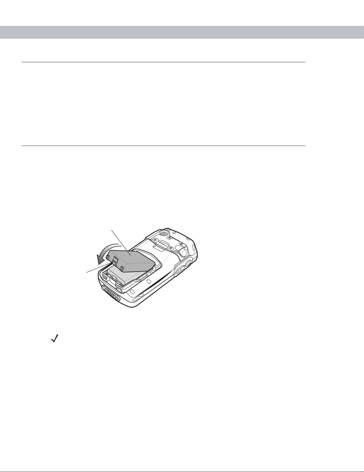
Installing the Main Battery
Before using the EDA, install a lithium-ion battery. The standard capacity 1900 mAh battery is shown. The
extended capacity 3800 mAh battery require s a la r ge r ca pacity batte r y cove r.
1. Insert the battery, top first, into the battery compartment in the back of the EDA.
2. Press the battery down into the battery compartment until the battery release latch snaps into place.
Battery
Release Latch
Figure 1-3
Inserting the Battery
NOTE Position the battery correctly, with the battery charging contacts on top of the charging
contacts in the battery compartment.
Page 23
Getting Started 1 - 5
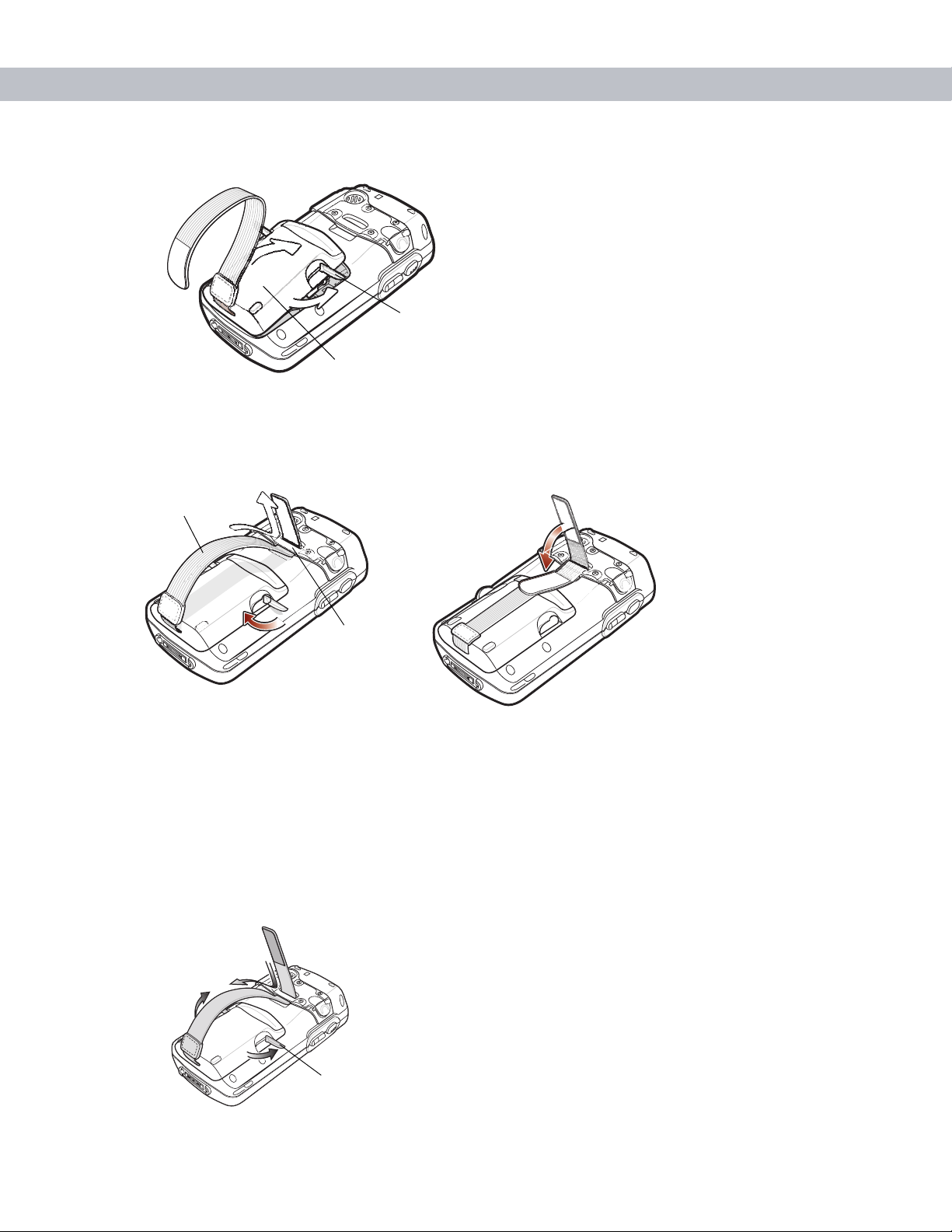
3. With the battery cover latches open, insert the cover, bottom first, then press down on the top of the cover.
Battery Cover Latch
Battery Cover
Figure 1-4
4. Close the battery cover latches on either side of the battery cover.
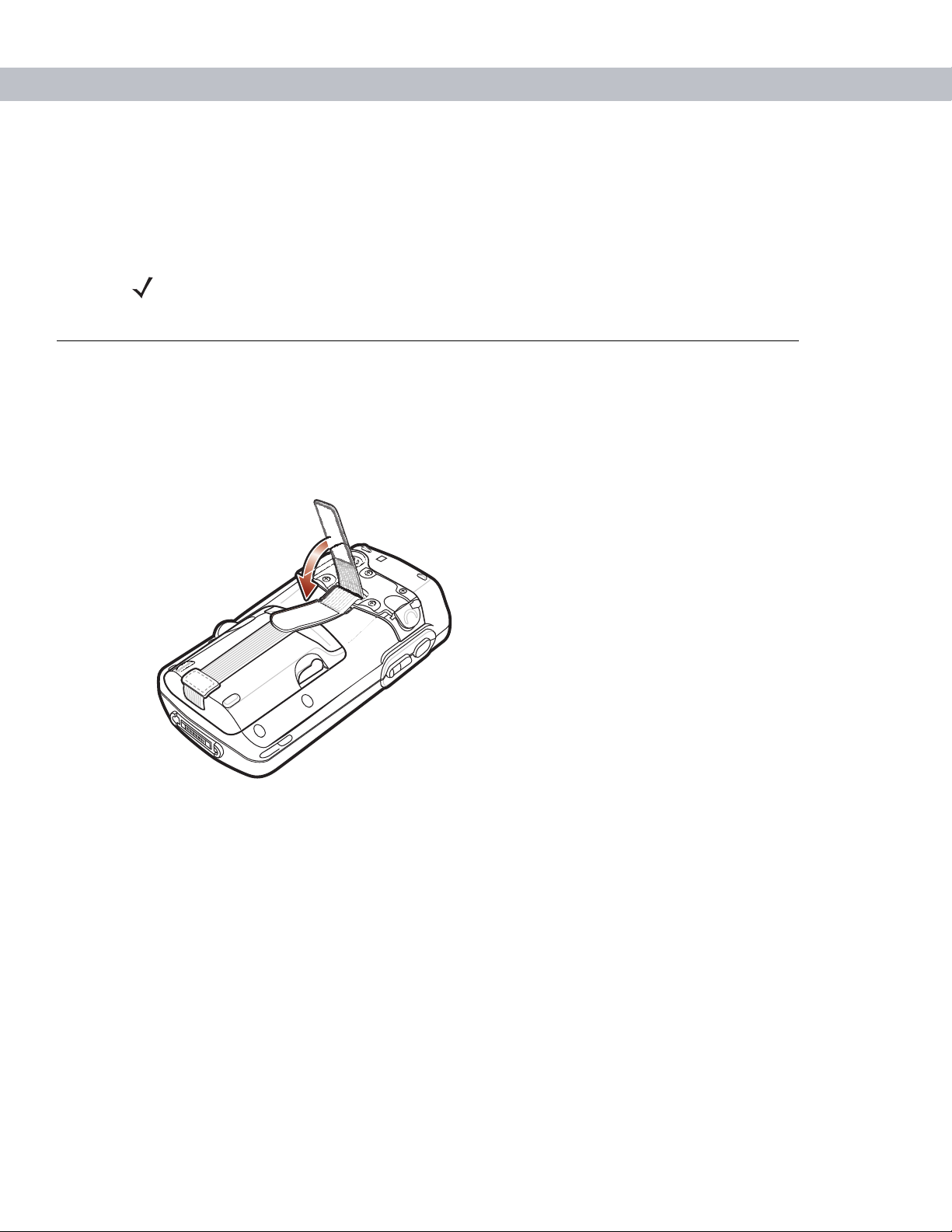
5. Insert the handstrap through the han ds tra p slot, th en tigh te n and pr ess down to secure.
Handstrap
Figure 1-5
Inserting the Battery Cover
Handstrap Slot
Inserting the Handstrap
The EDA powers up after inserting the battery.
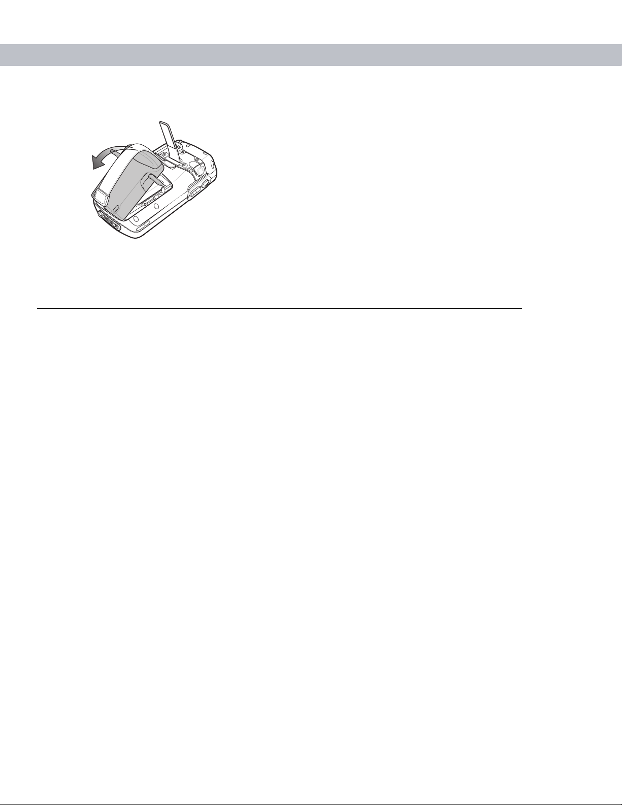
Removing the Main Battery
1. Press the red Power button to suspend the EDA.
2. Loosen the handstrap at the top of the EDA.
3. Open the battery cover latches on either side of the battery cover.
Battery Cover Latch
Figure 1-6
Opening the Battery Cover Latches
Page 24
1 - 6 MC70 User Guide
4. Lift the top of the battery cover and remove.
Figure 1-7
5. Press the battery release latch on the bottom of the battery to unlock, and lift the battery out of the well.
Removing the Battery Cover
Charging the Battery
Charging the Main Battery and Memory Backup Battery
Before using the EDA for the first time, charge the main battery until the amber Charge Status LED remains lit
(see Table 1-2 on page 1-7 for charge status indications). To charge the EDA, use a cable or a cradle with the
appropriate power supply. For information about the accessories available for the EDA, see Chapter 5,
Accessories.
The EDA is equipped with a memory backup battery which automatically charges from the fully-charged main
battery. When using the EDA for the first time, the backup battery requires approximately 24 hours to fully
charge. This is also true any time the backup battery is discharged, which occurs when the main battery is
removed for several hours. The backup battery retains RAM data in memory for at least 30 minutes (at room
temperature) when the EDA's main battery is removed. When the EDA reaches a very low battery state, the
combination of main battery and backup battery retains data in memory for at least 40 hours.
To charge batteries, use either a cable or on e of the follow ing cra dle s. Fo r crad le se tu p an d char gin g
procedures refer to the MC70 Integrator Guide.
•
Single Slot USB/Serial Cradle
•
Four Slot Ethernet Cradle
•
Vehicle Cradle.
Snap-on accessories such as the Magnetic Stripe Reader (MSR) and the Trigger Handle provide a
pass-through port for charging.
To charge the main battery:
1. Connect the charging accessory to the appropriate power source.
2. Insert the EDA into a cradle or attach the cable. The EDA begins chargi ng. Th e Char ge LED blinks a mbe r
while charging, then turns solid amber when fully charged. See Table 1-2 for charging indications.
Page 25

Getting Started 1 - 7
The standard capacity battery (1900 mAh) fully charge s in less th an four hours. The extended ca p acity batte ry
(3800 mAh) fully charges in less than eight hours.
Table 1-2
LED Charge Indicators
Charge Status LED Indication
Off EDA is not charging; EDA is not inserted correctly in the cradle or connected to
a power source; charger is not powered.
Slow Blinking Amber
EDA is charging.
(1 blink every 2 seconds)
Solid Amber Charging complete.
Note: When the battery is initially inserted in the EDA, the amber LED flashes
once if the battery power is low or the battery is not fully inserted.
Fast Blinking Amber
(2 blinks/second)
Charging error, e.g.:
•
Temperature is too low or too high.
•
Charging has gone on too long without completing (typically eight hours).
Charging Spare Batteries
Use one of the following accessories to charge a 1900 mAh or 3800 mAh spare battery:
•
Single Slot USB/Serial Cradle
•
Four Slot Battery Charger
•
VCD7000 Vehicle Cradle.
To charge a spare battery:
1. Connect the spare battery charging accessory to the appropriate power source.
2. Insert the spare battery into the accessory’s spare battery charging slot with the charging contacts facing
down (over the charging pins) and gently press down on the battery to ensure proper contact.
The battery begins charging. The amber charge LED on the accessory lights to show the charge status.
The standard spare battery fully charges in less than four hours, and the extended spare battery fully charges
in less than eight hours.
Page 26

1 - 8 MC70 User Guide
Charging Temperature
Charge batteries in temperatures from 0oC to 40oC (32°F to 104°F). Note that at temperatures above 35oC,
charging is intelligently controlled by the EDA and the charging accessory in order to ensure safe operation
and optimize long-term battery life.
To accomplish this, for small periods of time, the EDA or accessory alternately ena bles an d disables battery
charging to keep the battery at acceptable temperatures. The EDA or accessory indicates when charging is
disabled due to abnormal temperatures via its LED. See Table 1-2.
Powering On the EDA
Press the Power button to turn on the EDA. If the EDA does not power on, reset it. See Resetting the EDA on
page 2-24.
When turning the EDA on for the first time, the Symbol splash screen displays for about a minute as the EDA
initializes its flash file system, then the calibration window appears. Note that these windows also appear upon
cold boot.
NOTE When the EDA powers up after inserting a battery for the first time, the device boots and
powers on automatically.
Calibrating the Screen
To calibrate the screen so the cursor on the touch screen aligns with the tip of the stylus:
1. Remove the stylus from its holder on the back of the EDA.
2. Carefully press and briefly hold the tip of stylus on the center of each target that appears on the screen.
3. Repeat as the target moves around the screen, then tap the screen to continue.
Checking Battery Status
To check the charge status of the main battery or backup battery in the EDA, tap Start - Settings - System Power icon to display the Power window.
To save battery power, tap the Advanced tab and set the EDA to turn off after a specified number of minutes.
Page 27
SIM Card
GPRS phone service requires a Subscriber Identification Module (SIM) card, or smart card. Obtain this card
from the phone service provider. The card fits into the EDA and can contain the following information:
•
•
•
•
To install the SIM card:
1. Press the red Power button to suspend the EDA.
Getting Started 1 - 9
NOTE MC7004 and MC7094 only.
Mobile phone service provider account details.
Information regarding service access and preferences.
Contact information, which can be moved to Contacts on the EDA.
Any additional services to which you have subscribed.
NOTE For more information about SIM cards, refer to the mobile phone service provider's
documentation.
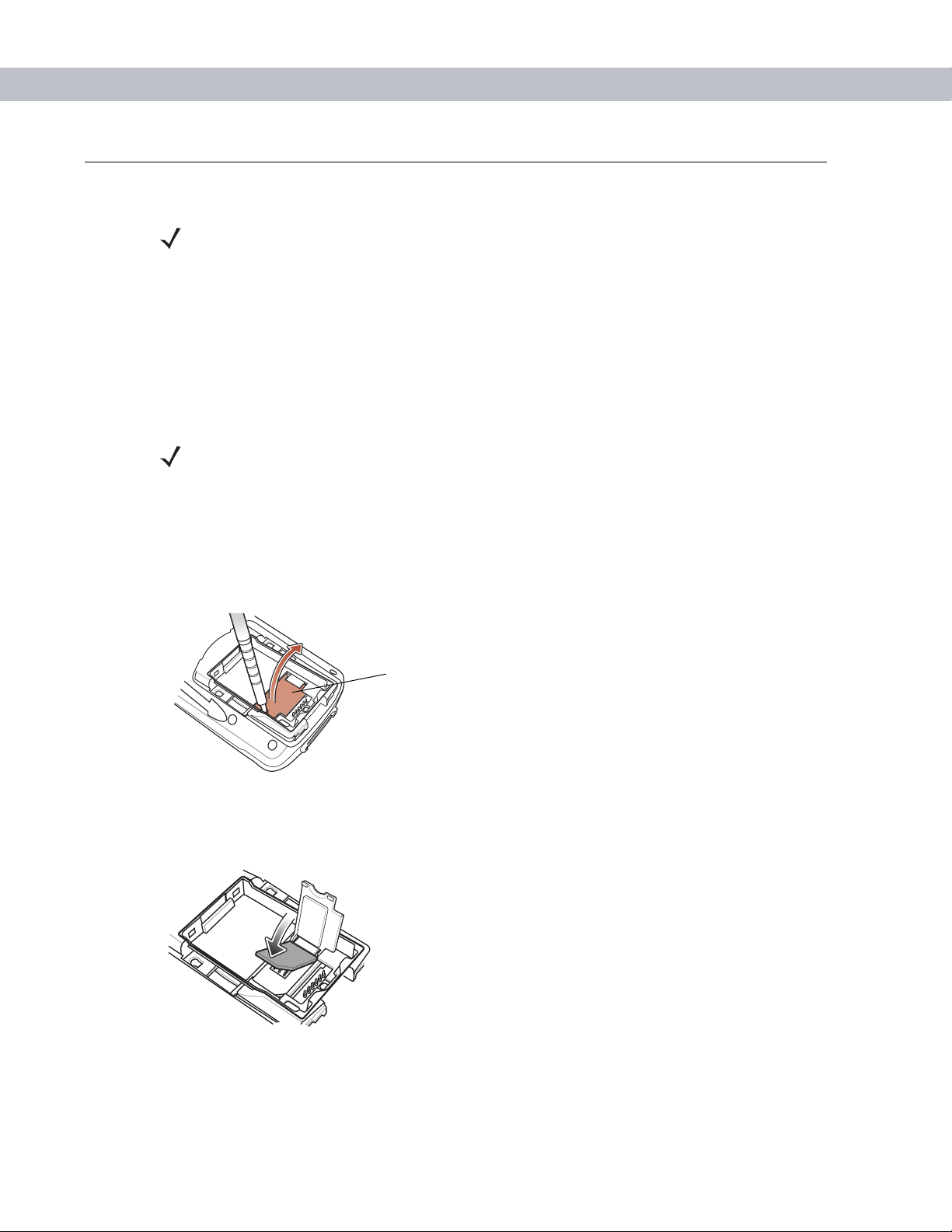
2. Remove the battery.
3. Lift the SIM cover using the stylus tip.
SIM Cover
Figure 1-8
4. Insert the SIM card, as shown in Figure 1-9, with the cut edge of the car d facing out and the conta cts facing
Lifting the SIM Cover
down.
Figure 1-9
5. Lower the SIM cover and snap it in place.
6. Replace the battery and battery cover.
Inserting the SIM Card
Page 28
1 - 10 MC70 User Guide
7. Press the red Power button.
8. Tap Start - Phone - Menu - Options - Network tab and verify that the service provider appears in the
Current network: field.
9. Make a call to verify connection.
NOTE For detailed information about WWAN ac tiv ation and settings, refer to the MC70 Integrator
Guide.
Adjusting the Handstrap
The EDA handstrap is attached to the bottom of the battery cover. Adjust the handstrap to increase comfort
when holding the EDA for extended periods of time. To adjust the handstrap:
1. Feed the handstrap through the handstrap slot in either direction, to tighten or loosen.
2. Secure the handstrap by pressing the two sides together as shown in Figure 1-10.
Figure 1-10
Handstrap Adjustment
Page 29
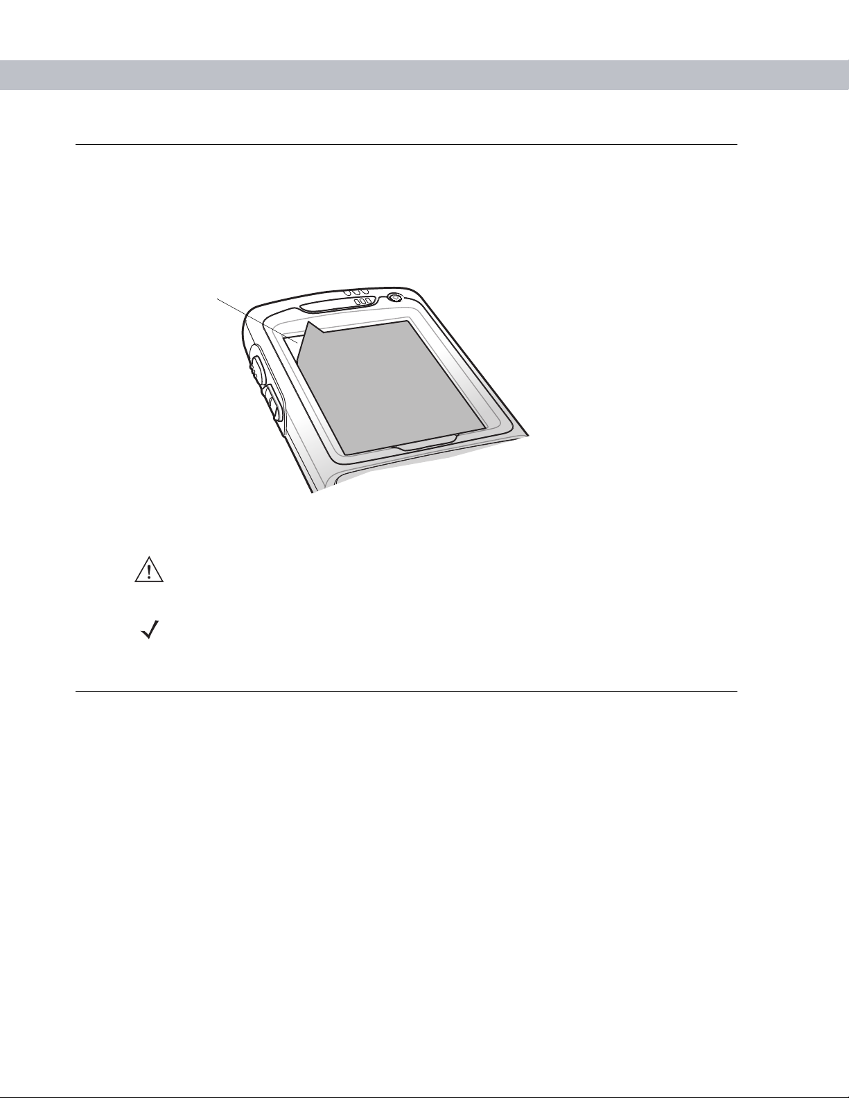
Removing the Screen Protector
A screen protector is applied to the MC70. Symbol recommends using this to minimize wear and tear. Screen
protectors enhance the usability and durability of touch screen displays.
To remove the screen protector, lift the corner using a thin plastic card, such as a credit card, then carefully lift
it off the display.
Lift Screen
Protector Corner
Getting Started 1 - 11
Figure 1-11
CAUTION Do not use a sharp object to remove the protector. Doing so can damage the display.
NOTE Not using a screen protector can affect warranty coverage. To purchase replacement
protectors, contact your local account manager or Symbol Technologies, Inc. These include screen
protector installation instructions. Part number: KT-67525-01 Screen Protector 3/pk.
Removing the Screen Protector
Battery Management
Observe the following battery saving tips:
•
Leave the EDA connected to AC power at all times when not in use.
•
Set the EDA to turn off after a short period of non-u se.
•
Set the backlight to turn off after a short period of non-use.
•
Turn off all wireless activities when not in use.
•
Power off the EDA when charging to charge at a faster rate.
Page 30

1 - 12 MC70 User Guide
Changing the Power Settings
To set the EDA to turn off after a short period of non-use:
1. Tap Start - Settings - System tab - Power icon - Advanced tab.
2. Select the On battery power: Turn off device if not used for check box and select a value from the
drop-down list.
3. Select ok.
Changing the Backlight Settings
To change the backlight settings in order to conserve more battery power:
1. Tap Start - Settings - System tab - Backlight icon - Battery Power tab.
2. Select the Disable backlight if device is not used for check box and select a value from the drop-down
list.
3. Select the Brightness tab.
4. Tap the Disable backlight check box to turn off the display backlight, or use the slider to set a low value
for the backlight.
5. Select ok.
Changing the Keypad Backlight Settings
To change the keypad backlight settings in order to cons er ve mor e battery power:
1. Tap Start - Settings - System tab - Keylight icon - Battery Power tab.
2. Select the On battery power: Disable keylight if device if not used for check box and select a value
from the drop-down list.
3. Select the Advanced tab.
4. Tap the Disable keylight check box to turn off the keypad backlight.
5. Select ok.
Turning Off the Radios
Turning Off the WLAN Radio
To turn off the WLAN radio, tap the Signal S trength ico n and select Disable Radio. A red X appears across the
icon indicating the radio is disabled (off).
To turn the WLAN radio back on, tap the Signal S trength icon and select En able Radio. The red X d isappears
from the icon indicating the radio is enabled (on).
Page 31

Getting Started 1 - 13
Turning Off the Bluetooth and WAN Radios
NOTE The Flight Mode feature only turns off the WAN and Bluetooth radios. Y ou must turn off the
WLAN radio sepa rately.
To turn off the Bluetooth and WAN radios:
•
Tap the Connectivity icon (on non-WAN devices) or the Antenna/Signal icon (on WAN
devices) and select Turn on flight mode
OR
•
Tap the Bluetooth icon and select Disable Bluetooth.
To turn on the Bluetooth and WAN radios:
•
Tap the Connectivity icon (on non-WAN devices) or the Antenna/Signal icon (on WAN
devices) and select Turn off flight mode
OR
•
Tap the Bluetooth icon and select Enable Bluetooth.
Page 32

1 - 14 MC70 User Guide
Page 33

Chapter 2 Using the MC70
Introduction
This chapter explains the buttons, status icons, and controls on the EDA, and provides basic instructions for
using the EDA, including powering on and resetting the EDA, and entering and capturing data.
Status Icons
The navigation bar at the top of the screen can contain the status icons listed in Table 2-1.
Chapter 2
Chapter 2
Using the MC70
Table 2-1
Icon Function Description
Status Icons
Speaker All sounds are on.
All sounds are off.
Vibrate is on.
Battery Backup battery is very low.
Main battery is charging.*
Main battery is low.
Main battery is very low.
Main battery is full.*
Connectivity Connection is active.
GPRS available.
GPRS in use.
EGPRS available.
EGPRS in use.
Synchronization is occurring.
* Only appears in the Time and Next Appointment dialog box.
Page 34

2 - 2 MC70 User Guide
Table 2-1
Icon Function Description
Status Icons (Continued)
WWAN Call missed.
Voice call.
Voice call in progress.
Calls are forwarded.
Call on hold.
Speakerphone is on.
Antenna/signal icon: wireless on/good signal.
Antenna/signal icon: wireless off.
Antenna/signal icon: no service or searching.
Roaming.
Time and Next
Appointment
Instant Message Notification that one or more instant messages were received.
E-Mail Notification that one or more e-mail messages were received.
Displays current time in analog or digital format.
Voice Mail Notification that one or more voice messages were received.
Multiple Notifications There are more notification icons than can be displayed. Tap to display
remaining icons.
* Only appears in the Time and Next Appointment dialog box.
Page 35

Using the MC70 2 - 3
The command bar at the bottom of the screen can contain the task tray icons listed in Table 2-2.
Table 2-2
Icon Description
Task Tray Icons
Wireless connection
Indicates WLAN signal strength.
status
Bluetooth Enabled Bluetooth radio is on.
Bluetooth Disabled Bluetooth radio is off.
ActiveSync Active connection between the EDA and the development PC.
Speaker Icon
To adjust the system volume using the Speaker icon in the navigation bar:
1. Tap the Speaker icon. The Volume dialog box appears.
Figure 2-1
2. Tap and move the slide bar to adjust the volume.
3. Select the On or Off radio button to turn the volume on or off.
Volume Dialog Box
You can also adjust the system volume using the Sounds & Notifications window, or use the Up/Down button
on the side of the EDA.
Page 36

2 - 4 MC70 User Guide
Battery Icon
Battery icons appear on the navigation bar when the main battery or backup battery power falls below a
predetermined level. A Battery dialog box also appears indicating the status of the main or backup battery.
Figure 2-2
Also view the battery status using the Power window.
Battery Status Dialog Box
Connectivity Icon
The Connectivity icon indicates the communication status of the EDA when it is connecting to the internet or
host computer.
Figure 2-3
Connectivity Dialog Box
Page 37

WWAN Icon
The WWAN icons indicate the status of the phone and antenna/signal.
Call in Progress
Using the MC70 2 - 5
Figure 2-4
WWANConnectivity Icon
Time Icon
The Time icon displays the current time in a digital or analog format. To change the time format, tap and hold
the Time icon until a menu appears. Select the format.
Analog ClockDigital Clock
Figure 2-5
Time Icon Format Menu
Page 38

2 - 6 MC70 User Guide
To display current date, time, and appointments, tap the Time icon to display the Time and Next Appointment
dialog box.
Battery Status Icon
Upcoming Appointments
Figure 2-6
Time and Next Appointment Dialog Box
Current Date and Time
The dialog box displays the current date and time, the battery status, and any upcoming appointments in the
Calendar.
Instant Message Icon
The Instant Message icon notifies you when MSN Messenger receives a new message.
Figure 2-7
MSN Messenger Dialog Box
Page 39

E-Mail Icon
The E-Mail icon notifies you when you receive incoming e-mails.
Using the MC70 2 - 7
Figure 2-8
New E-mail Messages Dialog Box
Multiple Notifications Icon
The Multiple Notifications icon appears when two or more message notifications occu r. Tap the icon to display
the multiple notification icons.
Multiple Notifications
Figure 2-9
Multiple Notifications Icon
Page 40

2 - 8 MC70 User Guide
LED Indicators
The MC70 has three LED indicators. The Scan/Decode LED indicates status for scanning. The Charge Status
LED indicates status for main battery charging. The Radio Power Status LED indicates radio status. Table 2-3
describes the LED indications.
Scan/Decode
Figure 2-10
Table 2-3
Charge
LED
Status LED
LED Indicators
LED Indications
LED State Indication
Radio Power
Status LED
Scan/Decode LED
Solid Green Successful decode/capture.
Solid Red Laser enabled, scanning/imaging in process.
Off Not enabled.
Charge Status LED
Slow Blinking Amber Main battery in EDA is charging.
Solid Amber Main battery in EDA is fully charged.
Fast Blinking Amber Charging error.
Off Not charging.
Radio Power Status LED*
Slow Blinking Green Any one of the radios is on.
Off No radio is on.
*The Radio Power St a tus LED is disabled by default. A registry setting change
is required to make this LED functional. Refer to the MC70 Integrator Guide.
NOTE For information about scanning/decoding, see Data Capture on page 2-20. For information
about radio status and settings, see Chapter 3, Using Bluetooth, Chapter 4, Using the
MC7004/MC7094 Phone, or refer to the MC70 Integrator Guide.
Page 41

Keypads
The EDA offers two modular keypad configurations: Numeric and QWERTY.
Numeric Keypad Configuration
The numeric keypad contains application keys, scroll keys, and function keys. The keypad is color-coded to
indicate the alternate function key (blue) values. Note that an application can change keypad functions so the
EDA’s keypad may not function exactly as described. See Table 2-4 for key and button descriptions and Table
2-5 on page 2-11 for the keypad’s special functions.
Using the MC70 2 - 9
F2
Figure 2-11
MC70 Numeric Keypad
Page 42

2 - 10 MC70 User Guide
Table 2-4
Blue Key (left) Use this key to launch applications or access items (shown on the keypad in blue).
Orange Key (right) Use this key to access the secondary layer of characters and actions (shown on the
Green/Red Phone MC7094 and MC7004:
MC70 Numeric Keypad Descriptions
Key Description
Press the Blue key once to activate this mode, followed by another key.
A single press displays the following icon at the bottom of the screen, until a second
key is pressed:
keypad in orange). Press the Orange key once to lock the keypad in to Alpha state.
A single press displays the following icon at the bottom of the screen:
Press the Orange key a second time to return to the normal state.
Press the Orange key , then the Shif t key to add a temporary shif t (that applies on ly to
the next key pressed) to the orange lock state. This displays the following icon at the
bottom of the screen:
Green Phone: press to display the phone keypad window or to dial a phone number
(from the phone keypad window).
Red Phone: press when the phone keypad window displays to stop dialing or end a
call.
.
Scan (yellow) Activates the scanner/imager in a scan enabled application.
Scroll Up and Down Moves up one item.
Moves left one item when pressed with the Orange key.
Scroll Left and Right Moves down one item.
Moves right one item when pressed with the Orange key.
Menu Accesses the command or menu above it on the screen.
Star Produces an asterisk in default state.
Press and release the blue key, then press the Star key to open the Start menu.
Page 43

Using the MC70 2 - 11
Table 2-4
MC70 Numeric Keypad Descriptions (Continued)
Key Description
Alphanumeric In default state, produces the numeric value on the key.
In Alpha state, produces the lower case alphabetic characters on the key. Each key
press produces the next alphabetic character in sequence. For example, press and
release the Orange key and then press the ‘4’ key once to produce the letter ‘g’; press
and release the Orange key and then press the ‘4’ key three times to produce the letter
‘i’.
Press the SHIFT key in Alpha state to produce the upper case alphabetic characters
on the key. For example, press and release the Orange key, press and release the
SHIFT key , and then press the ‘4’ key once to produce the letter ‘G’; press and relea se
the Orange key, press and release the SHIFT key and then press the ‘4’ key three
times to produce the letter ‘I’.
SPACE Produces a space.
BACKSPACE Produces a backspace.
SHIFT Press and release the SHIFT key to activate the keypad alternate SHIFT functions.
A single press displays the following icon at the bottom of the screen, until a second
key is pressed:
Press the Orange key , then the Shift key to add a temporar y shift (that applie s only to
the next key pressed) to the orange lock state. This displays the following icon at the
bottom of the screen:
ENT (Enter) Executes a selected item or function.
Pound Produces a pound/number sign.
Press and release the blue key, then press the Pound key to produce an OK.
Table 2-5
Key
Numeric Keypad Input Modes
Numeric Mode
Blue+
Key
SHIFT
+ Key
(Alpha Lowercase Mode)
1st Press
Orange Key
2nd
Press
3rd
Press
4th
Press
Orange + Shift Keys
(Alpha Uppercase Mode)
1st Press
2nd
Press
3rd
Press
4th
Press
1 1 F1! * **** ***
22F2@a bc A BC
33F3#d ef D EF
Note: An application can change the key functions. The keypad may not function exactly as described.
Page 44

2 - 12 MC70 User Guide
Table 2-5
Numeric Keypad Input Modes (Continued)
Numeric Mode
Key
Blue+
Key
SHIFT
+ Key
Orange Key
(Alpha Lowercase Mode)
1st Press
2nd
Press
3rd
Press
4th
Press
Orange + Shift Keys
(Alpha Uppercase Mode)
1st Press
2nd
Press
3rd
Press
4th
Press
44F4$g hi GHI
55F5%j kl J KL
66F6^mno MNO
77F7&p qrsP QRS
88F8*t uv T UV
9 9 F9 ( w xyzW XYZ
00F10). >
Up Up Up Hilight UpLeft Left
Down Down Down Hilight
Right Right
Down
Enter Action Action Action Action Action
Note: An application can change the key functions. The keypad may not function exactly as described.
Page 45

Using the MC70 2 - 13
QWERTY Keypad Configuration
The QWERTY keypad produces the 26-character alphabet (A-Z, both lowercase and uppercase), numbers
(0-9), and assorted characters. The keypad is color-coded to indicate which modifier key to press to produce a
particular character or action. The keypad default is alphabetic, producing lowercase letters. See Table 2-6 for
key and button descriptions and Table 2-7 on page 2-15 for the keypad’s special functions.
Figure 2-12
Table 2-6
QWERTY Keypad Configuration
QWERTY Keypad Descriptions
Key Action
Blue Key (left) Launches applications (shown on the keypad in blue).
•
Press the Blue key once to activate this mode temporarily, followed by
another key . This displays the following icon at the bottom of the screen, until
a second key is pressed:
•
Press the Blue key twice to lock this mode. This displays the following icon
at the bottom of the screen:
•
Press the Blue key a third time to unlock.
•
Press and hold the Blue key while selecting a sequence of keys to activate
this mode temporarily. This displays the following icon at the bottom of the
screen as long as the key is pressed:
Page 46

2 - 14 MC70 User Guide
Table 2-6
QWERTY Keypad Descriptions (Continued)
Key Action
Orange Key (right) Accesses the secondary layer of characters and actions (shown on the keypad in
orange).
•
Press the Orange key once to activate this mode temporarily, followed by
another key . This displays the following icon at the bottom of the screen, until
a second key is pressed:
•
Press the Orange key twice to lock this mode. This displays the following
icon at the bottom of the screen:
•
Press the Orange key a third time to unlock.
•
Press and hold the Orange key while selecting a sequence of keys to
activate this mode temporarily . This displays the following icon at the bottom
of the screen as long as the key is pressed:
Green/Red Phone MC7094 and MC7004:
Green Phone: press to display the phon e keypad window or to dial a phone number
(from the phone keypad window).
Red Phone: press when the phone keypad window displays to stop dialing or end
a call.
Scroll Up and Left Moves up one item.
Moves left one item when pressed with the Orange key.
Scroll Down and Right Moves down one item.
Moves right one item when pressed with the Orange key.
Menu Accesses the command or menu above it on the screen.
Shift Changes the state of the alpha characters from lowercase to uppercase.
•
Press the Shift key once to activate this mode temporarily, followed by
another key . This displays the following icon at the bottom of the screen, until
a second key is pressed:
•
Press the Shift key twice to lock this mode. This displays the following icon at
the bottom of the screen:
•
Press the Shift key a third time to unlock.
•
Press and hold the Shift key while selecting a sequence of keys to apply a
temporary shift. This displays the following icon at the bottom of the screen
as long as the key is pressed:
Page 47

Using the MC70 2 - 15
Table 2-6
QWERTY Keypad Descriptions (Continued)
Key Action
Backlight Turns the display backlight on and off.
Backspace Produces a backspace.
Enter Executes a selected item or function.
Star Produces an asterisk.
OK Use this key in conjunction with the Blue key as an OK or close button. This function
is user programmable.
Star t Menu Use this key in conjunction with the Blue key to instantly display the Start menu from
any application without tapping the screen. This function is user programmable.
Menu Use this key in conjunction with the Blue key to instantly display the context menu
from any application without tapping the screen. This function is user
programmable.
Phonepad Use this key in conjunction with the Blue key to display the Phonepad application
without tapping the screen. This function is user programmable.
Table 2-7
QWERTY Keypad Input Modes
Key Normal Shift + Key Orange + Key Blue + Key
Q q Q * Start Menu
W w W 1 Menu
E e E 2 Phone
Rr R 3
Tt T +
Yy Y _
Uu U Note: An application can change the key functions. The keyp ad may not function exactly as
described.
Page 48

2 - 16 MC70 User Guide
Table 2-7
Ii I =
Oo O “
Pp P áü OK
Aa A #
Ss S 4
Dd D 5
Ff F 6
Gg G (
Hh H )
Jj J /
Kk K :
Ll L ‘
BACKSPACE Backspace
QWERTY Keypad Input Modes (Continued)
Key Normal Shift + Key Orange + Key Blue + Key
Shift Shift
Zz Z 7
Xx X 8
Cc C 9
Vv V %
Bb B &
Nn N !
Mm M ?
,, <@
TAB Tab Back tab
SPACE Space
.. >0
ENTER Enter
Note: An application can change the key functions. The keyp ad may not function exactly as
described.
Page 49

Using the MC70 2 - 17
Special Character Key
NOTE Special characters are only available on the QWERTY keypad configurations.
To add special characters using the MC70 áü key, type the related character first, then press the Orange + áü
(P) key. Continue holding the Orange key and pressing the áü key until the special character displays. To
modify an existing character, move the cursor to the right of the character then press and hold the Orange key
and press the áü key until the special character replaces the original character. Table 2-8 lists the special
characters you can generate.
Table 2-8
Key Special Characters
a
A
c
C
d
D
e
E
i
I
l
L
n
Special Characters
N
o
O
p
P
r
R
s
S
t
Page 50

2 - 18 MC70 User Guide
Table 2-8
Key Special Characters
T
u
U
y
Y
z
Z
$
/
“
(
)
+
Special Characters (Continued)
!
.
*
@
%
,
#
&
_
‘
?
:
-
Page 51

Function Buttons
The EDA’s buttons perfor m ce rtain func tion s.
Scan/Action
Button
Up/Down Button
Using the MC70 2 - 19
Power Button
Action Button
Scan/Action Button
Stylus
Figure 2-13
•
Power: Press the red Power button to turn the EDA screen on and off. The EDA is in suspend mode
Function Buttons
when the screen is off. For more information, see Poweri ng On the EDA on page 1-8. Also use the
Power button to reset the EDA by performing a warm or cold boot. See Resetting the EDA on page 2-24.
•
Scan/Action: Press to scan bar codes or captur e im ag es . See Data Captur e on page 2-20 .
®
Or, press to open an application or perform a function. See the Microsoft
Applications for Mobile and CE
5.0 User Guide to set an application to open.
•
Up/Down: Press to increase or decrease the EDA’s volume.
•
Action: Press to open an application or perform a function. See the Microsoft® Applications for Mobile
and CE 5.0 User Guide to set an application to open.
Use the EDA stylus to select items and enter information. The stylus functions as a mouse.
•
Tap: Touch the screen once with th e sty lus to pre ss op tio n bu tto n s an d open me nu item s.
•
Tap and Hold: Tap and hold the stylus on an item to see a list of actions available for that item. On the
pop-up menu that appears, tap the action to perform.
•
Drag: Hold the stylus on the screen and drag across the screen to select text and images. Drag in a list to
select multiple items.
NOTE Symbol recommends using the spring-loaded tip of the stylus to write on the screen, and
the back end of the stylus to tap the screen. Use your finger to press the Power button and
keypad buttons.
Page 52

2 - 20 MC70 User Guide
CAUTION To prevent damage to the screen, do not use any device other than the Symbol-provided
!
stylus.
Using a Headset
You can use a stereo headset for audio communication when using an audio-enabled application. To use a
headset, plug the headset jack into the audio connector on the side of the EDA. Set the EDA’s volume
appropriately before putting the headset on. Plugging a headset into the jack mutes the speaker.
For the best audio performance, symbol recommends a 2.5mm jack headset, p/n 50-11300-050.
Figure 2-14
Data Capture
The MC70 offers two types of data capture options:
•
Linear scanning
•
Imaging.
Linear Scanner
Figure 2-15
Using a Headset
Imager
Data Capture Configurations
Page 53

Using the MC70 2 - 21
Linear Scanning
EDAs with an integrated linear scanner have the following features:
•
Reading of a variety of bar code symbologies, including the most popular linear, postal, and 1-D code
types.
•
Intuitive aiming for easy point-and-shoot operation.
Imaging
EDAs with an integrated imager have the following features:
•
Omnidirectional reading of a variety of bar code symbologies, including the most popular linear, postal,
PDF417, and 2D matrix code types.
•
The ability to capture and download images to a host for a variety of imaging applications.
•
Advanced intuitive laser aiming for easy point-and-shoot operation.
The imager uses digital camera technology to take a digit al picture of a bar code, stores the resulting image in
its memory, and executes state-of-the-art software decoding algorithms to extract the data from the image.
Operational Modes
EDAs with an integrated imager support three mode s of o peration, listed below. Activate each mode by pulling
the trigger or pressing the Scan button.
•
Decode Mode: In this mode, the EDA attempts to locate and decode enable d bar codes within it s field of
view. The imager remains in this mode as long as you hold the trigger, or until it decodes a bar code.
•
Pick List Mode: This mode allows you to selectively decode a bar code when more than one b ar code is
in the EDA’s field of view. To accomplish this, move the aiming crosshair over the required bar code to
decode only this bar code. This feature is ideal for pick lists containing multiple bar codes and
manufacturing or transport labels containing more than one bar code type (either 1D or 2D).
•
Image Capture Mode: Use this mode to capture an image within the EDA’s field of view. This is useful
for capturing signatures or images of items like damaged boxes.
Scanning Considerations
Typically, scanning is a simple matter of aim, scan, and decode and a few quick trial efforts master it. However ,
consider the following to optimize scanning perf or ma n ce :
•
Range
Any scanning device decodes well over a particular wo rking ra nge — min imum an d ma ximu m d istances
from the bar code. This range varies according to bar code de nsity and scanning device optics.
Scanning within range brings quick and constant decodes; scanning too close or too far away prevents
decodes. Move the scanner closer and further away to find the right working range for the bar codes
being scanned.
Page 54

2 - 22 MC70 User Guide
•
Angle
Scanning angle is important for promoting quick decodes. Wh en laser beams reflect directly back into the
scanner from the bar code, this specular reflection can “blind” the scanner.
To avoid this, scan the bar code so that the beam does not bounce directly back. But don’t scan at too
sharp an angle; the scanner needs to collect scattered reflections from the scan to make a successful
decode. Practice quickly shows what tolerances to work within.
•
Hold the EDA farther away for larger symbols.
•
Move the EDA closer for symbols with bars that are close together.
NOTE Scanning procedures depend on the application and EDA configuration. An application may
use different scanning procedures from the one listed above.
Linear Scanning
1. Ensure that a scan enabled application is loaded on the EDA.
2. Aim the scan window at the bar code.
Figure 2-16
3. Press the scan button. Ensure the red scan beam covers the entire bar code. The Scan/Decode LED lights
Linear Scanning
red to indicate that scanning is in process, then lights green and a beep sounds, by default, to indicate the
bar code was decoded successfully.
Figure 2-17
Correct
Linear Scanner Aiming Pattern
Incorrect
Page 55

Imager Scanning
1. Ensure that a scan-enabled application is loaded on the EDA.
2. Aim the scan window at the bar code.
Using the MC70 2 - 23
Figure 2-18
3. Press the scan button. The red laser aiming pattern turns on to assist in aiming. Ensure the bar code is
Imager Scanning
within the area formed by the brackets in the aiming pattern. The Scan/Decode LED lights red to indicate
that scanning is in process, then lights green and a beep sounds, by default, to indicate the bar code was
decoded successfully. Note that when the EDA is in Pick List Mode, the imager does not decode the bar
code until the crosshair touches the bar code.
Linear bar code
Figure 2-19
Symbol
View Finder
(Aiming Pattern)
Correct
Imager Aiming Pattern: Bar Code Centered
PDF417 symbol
Correct
Figure 2-20
Incorrect
Imager Aiming Pattern: Bar Code Not Centered
Page 56

2 - 24 MC70 User Guide
Figure 2-21
4. Release the scan button.
NOTE Imager decoding usually occurs instantaneously. The EDA repeats the steps required to
take a digital picture (image) of a poor or difficult bar code as long as the scan button remains
pressed.
Pick List Mode with Multiple Bar Codes in Aiming Pattern
Resetting the EDA
There are two reset functions, warm boot and cold boot. A warm boot restarts the EDA by closing all running
programs. A cold boot also restarts the EDA, and also resets the clock. Data saved in flash memory or a
memory card is not lost.
Perform a warm boot first. If the EDA still does not respond, perform a cold boot.
Performing a Warm Boot
Hold down the Power button for approximately five seconds. As soon as the EDA starts to boot release the
Power button.
Performing a Cold Boot
To perform a cold boot simultaneously press the Power button an d the 1 and 9 keys.
Page 57

Using the MC70 2 - 25
Waking the EDA
The wakeup conditions define what actions wake up the EDA. These settings are configurable and th e facto ry
default settings shown in Table 2-9 are subject to change/update.
Table 2-9
Power Off
(Suspend Mode)
Auto Off When the EDA suspends by an automatic
Wakeup Conditions (Default Settings)
Status Description Conditions for Wakeup
Locking the EDA
When the EDA suspends by pressing
Power, these actions wake the EDA.
power-off function, these actions wake the
EDA.
1. Power button is pressed.
2. AC power added or removed.
3. Cradle/cable connect or disconnect.
Key or scan button is pressed.
Real Time Clock set to wake up.
Incoming phone call (MC7004/7094 only)
1. Power button is pressed.
2. AC power added or removed.
3. Cradle/cable connect or disconnect.
Key or scan button is pressed.
Real Time Clock set to wake up.
Incoming phone call (MC7004/7094 only)
Use the Device Lock feature to prevent use of the device. Note that when locked, the EDA does not respond to
screen or keypad input.
To lock the device, tap the Device unlocked icon. The icon changes to locked.
Figure 2-22
Device Locked/Unlocked Icons
Page 58

2 - 26 MC70 User Guide
To unlock the device and free it for use, tap Unlock.
Figure 2-23
Tap Unlock on the Unlock Device window.
Unlock Device Window
Page 59

Chapter 3 Using Bluetooth
Introduction
Bluetooth-equipped devices can communicate without wires, using frequency-hopping spread spectrum
(FHSS) radio frequency (RF) to transmit and receive data in the 2.4 GHz Industry Scie ntific and Med ical (ISM )
band (802.15.1). Bluetooth wirele ss tec hno l og y is spec ifica lly de sig ne d for sho r t-r an g e (3 0 fe et/ 10 mete rs)
communication and low power consumption.
EDAs with Bluetooth capabilities can exchange information (e.g., files, appointments, and tasks) with other
Bluetooth enabled devices such as phones, printers, access points, and other mobile computers. To use the
Bluetooth phone as a modem, create a dial-up modem connection between the Bluetooth mobile computer
and a Bluetooth enabled phone.
Symbol mobile computers with Bluetooth techno lo gy use the StoneStreet Bluetoot h stack. To program
Bluetooth within the EDA refer to the Microsoft Embedded Visual C++ help.
Chapter 3
Using Bluetooth
Adaptive Frequency Hopping
Adaptive Frequency Hopping (AFH) is a method of avoiding fixed frequency interferers, and can be used with
Bluetooth voice. All devices in the piconet (Bluetooth network) must be AFH-capable in order for AFH to work.
There is no AFH when connecting and discovering devices. Avoid making Bluetooth connections and
discoveries during critical 802.11b communications. AFH for Bluetooth consists of four main sections:
•
Channel Classification - A method of detecting an interference on a channel-by-channel basis, or
pre-defined channel mask.
•
Link Management - Coordinates and distributes the AFH information to the r est of the Bluetooth n etwork.
•
Hop Sequence Modification - Avoids interference by selectively reducing the number of hopping
channels.
•
Channel Maintenance - A method for periodically re-evaluating the channels.
When AFH is enabled, the Bluetooth radio “hops around” (instead of through) the 802.11b high- rate channels.
AFH coexistence allows Symbol mobile computers to operate in any infrastructure.
The Bluetooth radio in this EDA operates as a Class 2 device power class. The maximum output power is
2.5mW and the expected range is 32.8 feet (10 meters). A definition of ranges based on power class is difficult
to obtain due to power and device differen ces, and wh ethe r on e measu res op en sp a c e or closed office space.
NOTE It is not recommended to perform Bluetooth wireless technology inquiry when high rate
802.11b operation is required.
Page 60

3 - 2 MC70 User Guide
Security
The current Bluetooth specification defines security at the link level. Application-level security is not specified.
This allows application developers to define security mechanisms tailored to their specific need. Link-level
security occurs between devices, not users, while application-level se curity can be imple mented o n a per- user
basis. The Bluetooth specification defines security algorithms and procedures needed to authenticate devices,
and if needed, encrypt the data flowing on the link between the devices. Device authentication is a mandatory
feature of Bluetooth while link encryption is optional.
Pairing of Bluetooth devices is accomplished by creating an initialization key that is used to authenticate the
devices and create a link key for them. Entering a commo n PIN number in th e de vices b ein g paired generates
the initialization key. The PIN number is never sent over the air. By default, the Bluetooth stack responds with
no key when a key is requested (it is up to user to respond to the key request event). Authentication of
Bluetooth devices is based-upon a challenge-response transaction. Bluetooth allows for a PIN number or
passkey that is used to create other 128-bit keys used for security and encryption. The encryption key is
derived from the link key used to authenticate the pairing devices. Also worthy of note is the limited range and
fast frequency hopping of the Bluetooth radios that makes long-distance eavesdropping difficult.
Recommendations are:
•
Perform pairing in a secure environment
•
Keep PIN codes private and don't store the PIN codes in the mobile computer
•
Implement application-level security.
Turning the Bluetooth Radio Mode On and Off
Turn off the Bluetooth radio to save p ower or if entering an area with radio re strictions (e.g., an airplane). When
the radio is off, other Bluetooth devices cannot see or connect to the EDA. Turn on the Bluetooth radio to
exchange information with other Bluetooth devices (within range). Communicate only with Blueto oth radios in
close proximity.
NOTE To achieve the best battery life in EDAs with multiple radios, turn off radios not in use.
Page 61

Using Bluetooth 3 - 3
Disabling Bluetooth
To disable Bluetooth, tap Bluetooth icon - Disable Bluetooth. The Bluetooth icon changes to indicate that
Bluetooth is disabled.
Figure 3-1
Disable Bluetooth
Enabling Bluetooth
To enable Bluetooth, tap Bluetooth icon - Enable Bluetooth. The Bluetooth icon changes to indicate that
Bluetooth is enabled.
Figure 3-2
Enable Bluetooth
Bluetooth Power States
Cold Boot
Performing a cold boot on the EDA turns off Bluetooth after initialization (which takes a few moments). It is
normal to see the Bluetooth icon appear and disappear , as well as a wait cursor , when initialization proceeds in
all modes.
Page 62

3 - 4 MC70 User Guide
Warm Boot
Performing a warm boot on the EDA returns Bluetooth to the last state after initialization.
Suspend
Suspending the EDA turns off Bluetooth.
NOTE Suspending the EDA powers off the Bluetooth radio and drops the piconet (Bluetooth
connection). When the EDA resumes, it take approximately 10 seconds for the Bluetooth radio
driver to re-initialize the radio.
Resume
When the EDA resumes, Bluetooth turns on if it was on prior to suspend.
Modes
The BTExplorer application has two mode for managing Bluetooth connections: Wizard Mode and Explorer
Mode. The Wizard Mode is for novice Bluetooth users and the Explorer Mode is for experienced Bluetooth
users. To switch between modes, select View - Wizard Mode or View - Explorer Mode.
Wizard Mode
Wizard Mode provides a simple process for discovering and connecting to Bluetooth devices.
NOTE Switching between Wizard Mode and Explorer Mode closes all active connections.
The following steps provide an example for using the Wizard to connect to remote devices.
1. Tap the Bluetooth icon and select Show BTExplorer. The BTExplorer window appears.
2. Tap File - New Connection. The New Connection Wizard window appears.
Figure 3-3
New Connection Wizard Window
Page 63

Using Bluetooth 3 - 5
3. Select an action from the drop-down list. Options include:
•
Explore Services on Remote Device
•
Pair with a Remote Device
•
Active Sync via Bluetooth
•
Browse Files on Remote Device
•
Connect to Headset
•
Connect to Internet Using Access Point
•
Connect to Internet Using Phone/Modem
•
Connect to a Personal Area Network
•
Send or Exchange Objects
•
Associate Serial Port.
NOTE If you select Active Sync via Bluetooth, ensure that the Bluetooth software is set up
properly on the host device.
4. Tap Next. The BTExplorer searches for Bluetooth devices in the area and displays the devices in the
Select Remote Device window.
Figure 3-4
Select Remote Device Window
5. Select a device from the list and then tap Next. The Conn ection Favorite Options window appears.
Figure 3-5
Connection Favorite Options Window
Page 64

3 - 6 MC70 User Guide
6. Select the Save As Favorite check box to save this service in the Favorite view.
7. In the Favorite Name text box, enter a name for this service that will appear in the Favorite list.
8. Tap Next. The Connection Summary window appears.
Figure 3-6
9. Tap Connect to connect to the service.
Connection Summary Window
Explorer Mode
The Explorer Mode window is easy to navigate and provides greater control to users familiar with Bluetooth.
The menu bar provides quick access to the options and tools used to connect to devices. To access Explorer
Mode, tap View - Explorer Mode.
Figure 3-7
Explorer Mode Window
Page 65

You can also use the “tap and hold” technique to view available options. Scroll bars and view options are
similar to those on the Windows desktop. The tree structure lists the following sub-items:
•
Local Device - This EDA
•
Remote Device - Other Bluetooth devices
- Trusted Devices - Bonded (paired) Bluetooth devices
- Untrusted Devices - Discovered devices that are not bonded
•
Favorites - Selected services that are set as Favorite for quick access.
NOTE Switching between Wizard Mode and Explorer Mode closes all active connections.
Discovering Bluetooth Device(s)
The EDA can receive information from discovered devices without bonding. However, once bonded, the EDA
and a bonded device exchange information automatically when you turn the Bluetooth radio on.
To find Bluetooth devices in the area:
Using Bluetooth 3 - 7
1. Ensure that the Bluetooth device to discover is in discoverable mode.
2. Ensure that the two devices are within 30 feet (10 meters) of one another.
3. Tap the Bluetooth icon and select Show BTExplorer. The BTExplorer windo w appears.
Figure 3-8
BTExplorer Window
Page 66

3 - 8 MC70 User Guide
4. Tap and hold Remote Devices and select Discover Devices from the pop-up menu. The EDA searches for
Bluetooth devices in the area.
Figure 3-9
The discovered devices display in the Untrusted Devices folder.
Figure 3-10
Discover Devices
Discovered Devices Listed in Untrusted Folder
Bonding with Discovered Device(s)
A bond is a relationship created between the EDA and another Bluetooth device in order to exchange
information in a secure manner. Creating a bond involves entering the same PIN on the two devices. After
creating a bond and turning on the Bluetoot h ra dio s, the de vice s re co gn ize the bon d and can exchange
information without re-entering a PIN.
Page 67

To bond with a discovered Bluetooth device:
1. Discover remote devices. See Discovering Bluetooth Device(s) on page 3-7.
2. In the Untrusted Devices folder, tap and hold on a device to pair with.
Using Bluetooth 3 - 9
Figure 3-11
3. Select Pair from the pop-up menu. The PIN Code Request window appears.
Figure 3-12
4. In the PIN Code: text box, enter the PIN number (between 1 and 16 characters) and then tap OK.
5. On the remote device, enter the same PIN number.
Pairing a Remote Device
PIN Code Request Window
Page 68

3 - 10 MC70 User Guide
6. The devices pair and the device name moves to the Trusted Devices folder.
Figure 3-13
Bonded (Paired) Discovered Device
Renaming a Bonded Device
To rename a bonded device:
1. Launch BTExplorer.
2. Tap and hold the device to rename.
Figure 3-14
Rename Device Selection Dialog Box
Page 69

3. Select Rename in the pop-up menu. The Change Device Name window appears.
Using Bluetooth 3 - 11
Figure 3-15
4. Enter a new name for the bonded device in the text box. Tap OK.
Change Device Name Window
Deleting a Bonded Device
To delete a device no longer needed:
1. Launch BTExplorer.
2. Tap and hold the device to delete and select Delete in the pop-up menu.
Figure 3-16
3. A confirmation dialog appears. Tap Yes.
Deleting a Bonded Device
Page 70

3 - 12 MC70 User Guide
Accepting a Bond
When a remote device wants to bond with the EDA, enter a PIN when requested to grant permission.
1. Ensure that the EDA is set to discoverable and connectable. See Bluetooth Settings on page 3-25.
When prompted to bond with the remote device the PIN Code Request window appears.
Figure 3-17
2. In the PIN Code: text box, enter the same PIN entered on the device requesting the bond. The PIN must
be between 1 and 16 characters.
3. In the Device Name: text box, edit the name of the device requesting the bond, if desired.
4. Tap OK to create the bond. The EDA can now exchange information with the other device.
PIN Code Request Window
Discovering Services
Before using services, first discover remote devices and then bond to those devices.
To determine what services are available on a bonded remote device:
1. Tap the Bluetooth icon and select Show BTExplorer.
2. In BTExplorer window, tap and hold on the remote device and select Explore from the pop-up menu.
Figure 3-18
Discovering Services
Page 71

Using Bluetooth 3 - 13
The EDA communicates with the remote device and lists the services under the device name.
Figure 3-19
List of Discovered Services
Some examples of available services are:
•
File Transfer Services
•
Dial-Up Networking Services
•
OBEX Object Push Services
•
Headset or Hands-Free Services
•
Serial Port Services.
See the following sections for information on these services.
File Transfer Services
To transfer files between the EDA and another Bluetooth enabled device:
1. Ensure the EDA is discoverable and connectable. See Bluetooth Settings on page 3-25.
2. Discover and bond (pair) with the remote access poin t. See Bonding with Discovered Device(s) on page
3-8.
3. In BTExplorer, select the Remote Devices folder.
4. Select the Trusted Devices folder.
5. Tap the remote device folder.
6. Tap and hold on the remote device and select Explore from the pop-up menu.
7. Tap and hold on File Transfer and select Connect. The remote device’s accessible folders appear.
Page 72

3 - 14 MC70 User Guide
8. Select a folder. The contents of the folder appear in the sub-window.
Figure 3-20
9. Tap and hold on the file. A pop-up menu appears.
10. Select the action to perform:
•
New - create a new file or folder on the remote device
•
Delete - delete the selected file on the remote device.
•
Get File - copy the file from the remote device to the EDA.
•
Put File - copy a file from the EDA to the remote device.
Remote Device Folders
Creating a New File or Folder
To create a new folder or file on the remote device:
1. Tap and hold on the file and select New - Folder or New - File. The Create New Folder or Create New File
window appears.
2. Enter the name for the new folder or file.
3. Tap OK to create the new folder or file on the remote device.
Deleting a File
To delete a file from the remote device:
1. Tap and hold on the file and select Delete.
2. In the Delete Remote Device File dialog box tap OK.
Getting a File
To copy a file from a remote device:
1. Tap and hold on the file and select Get. The Save Remote File window appears.
2. Navigate to the directory to save the file.
3. Tap Save. The file is transferred from the remote device to the EDA.
Page 73

Using Bluetooth 3 - 15
Copying a File
To copy a file to a remote device:
1. Tap and hold on the file and select Put. The Send Local File window appears.
2. Navigate to the directory to save the file and select a file.
3. Tap Open. The file copies from the EDA to the remote device.
Connecting to the Internet Using an Access Point
This section explains how to access a Bluetooth-enabled LAN access point (AP) for a network connection. Use
Internet Explorer to connect to a server.
1. Ensure the EDA is discoverable and connectable. See Bluetooth Settings on page 3-25.
2. Discover and bond (pair) with the remote access poin t. See Bonding with Discovered Device(s) on page
3-8.
3. In BTExplorer, select the Remote Devices folder.
4. Select the Trusted Devices folder.
5. Tap the remote device folder.
6. Tap and hold on the remote device and select Explore from the pop-up menu.
7. Tap and hold LAN Access using PPP service and select Connect from the pop-up menu. The EDA
connects with the access point.
8. Tap Start - Internet Explorer. The Internet Explorer window appears.
9. In the address field, enter an internet address and tap the Enter button. The web page loads.
Dial-Up Networking Services
To use a phone that has Bluetooth capabilities as a modem for the EDA, create a Bluetooth modem connection
on the EDA and send information to the phone using Bluetooth. The phone relays the information over the
phone line and sends back to the EDA any information that was requested over the connection. After creating
a modem connection to the Bluetooth phone, you can reuse it.
Prior to creating a connection, ensure the following:
•
Bluetooth phone is turned on.
•
Bluetooth phone is discoverable. (Some phones must also be pairable to accept a bonding request. For
more information, refer to the phone documentation.)
•
EDA’s and phone's Bluetooth radios are turned on.
•
EDA and phone are within range of each other (30 feet/10 meters).
Page 74

3 - 16 MC70 User Guide
Before setting up dial-up networking, obtain dial-up information and other necessary settings for the office
network or ISP. To create a new Bluetooth connectio n:
1. Ensure the EDA is discoverable and connectable. See Bluetooth Settings on page 3-25.
2. Discover and bond (pair) with the remote device. See Bonding with Discovered Device(s) on page 3-8.
3. In BTExplorer, select the Remote Devices folder.
4. Select the Trusted Dev ice s folder.
5. Tap the remote device folder.
6. Tap and hold on Dial-up Networking and select Connect from the pop-up menu. The Select Dial-up
Networking Entry window appears.
Figure 3-21
NOTE If a dial-up entry is not listed, see Adding a Dial-up Entry on page 3-18.
7. Select a dial-up entry.
8. Tap OK. The EDA begins to communicate with the phone. If required, the phone requests permission to
Select Dial-up Networking Entry Window
communicate with the EDA.
9. Confirm the connection on the phone. The Network Log On window appears.
Figure 3-22
Network Log On Window
Page 75

10. In the User name: text box, enter the user name for this connection.
11. In the Password: text box, enter the password for this connection.
12. In the Domain: text box, enter the domain for this connection, if required.
13. Tap OK. The phone begins dialing, then connects to the network.
Using Bluetooth 3 - 17
Figure 3-23
14. To end a sessio n, tap the Connection icon and then tap Disconnect in the dialog box.
Figure 3-24
Connecting to Bluetooth Phone
Connectivity Dialog Box
Page 76

3 - 18 MC70 User Guide
Adding a Dial-up Entry
To add a dial-up entry:
1. In the Select Dial-up Networking Entry window, t a p an d hold, then se lect Add Entry from the pop-up menu.
Figure 3-25
Add Dial-Up Entry
The Add Phone Book Entry window appears.
2. In the Name for the connection: text box, enter a name for this connection.
3. In the Country Code: text box, enter the country code for the country that you are calling.
4. In the Area Code: text box, enter the area code.
5. In the Phone Number: text box, enter the phone num b er.
6. Tap OK.
Page 77

Using Bluetooth 3 - 19
Object Exchange Push Services
Object Exchange (OBEX) is a set of protocols that allows sharing objects such as Contacts or pictures using
Bluetooth.
To exchange contact information with another Bluetooth enabled device:
1. Ensure the EDA is discoverable and connectable. See Bluetooth Settings on page 3-25.
2. Discover and bond (pair) with the remote device. See Bonding with Discovered Device(s) on page 3-8.
3. In BTExplorer, select the Remote Devices folder.
4. Select the Trusted Devices folder.
5. Tap the remote device folder.
6. Tap and hold on OBEX Object Push and select Connect. The OBEX Object Push window appears.
7. In the Action drop-down list, select one of the following options: Send Contact Information, Swap Contact
Information, Fetch Contact Information, or Send a Picture.
Sending a Contact
To send a contact to another device:
1. Ensure the EDA is discoverable and connectable. See Bluetooth Settings on page 3-25.
2. Discover and bond (pair) with the remote device. See Bonding with Discovered Device(s) on page 3-8.
3. In BTExplorer, select the Remote Devices folder.
4. Select the Trusted Devices folder.
5. Tap the remote device folder.
6. Tap and hold on OBEX Object Push and select Connect. The OBEX Object Push window appears.
Figure 3-26
7. In the Action: drop-down list, select Send Contact Information.
OBEX Object Push Window
Page 78

3 - 20 MC70 User Guide
8. Tap . The Select Contact Entry window appears.
Figure 3-27
9. Select a contact to send to the other device.
10. Tap OK.
11. Tap OK to send the contact to the other device and display a confirmation dialog box on the other device to
Select Contact Entry Window
accept the contact. A Send Contact dialog appears.
12. Tap Ok.
Sending a Picture
To send a picture to another device:
1. Ensure the EDA is discoverable and connectable. See Bluetooth Settings on page 3-25.
2. Discover and bond (pair) with the remote device. See Bonding with Discovered Device(s) on page 3-8.
3. In BTExplorer, select the Remote Devices folder.
4. Select the Trusted Dev ice s folder.
5. Tap the remote device folder.
Page 79

Using Bluetooth 3 - 21
6. Tap and hold on OBEX Object Push and select Connect. The OBEX Object Push window appears.
Figure 3-28
7. In the Action: drop-down list, select Send A Picture.
8. Tap . The Send Local Picture window appears.
Figure 3-29
9. Navigate to the picture to send to the other device.
10. Tap Open.
OBEX Object Push Window
Send Local Picture Window
11. Tap OK to send the picture to the other device and display a confirmation dialog box on the other device to
accept the picture. A Send Picture dialog appears.
12. Tap Ok.
Headset Services
To connect to a Bluetooth headset:
1. Ensure the EDA is discoverable and connectable. See Bluetooth Settings on page 3-25.
2. Discover and bond (pair) with the headset. See Bonding with Discovered Device(s) on page 3-8.
3. In BTExplorer, select the Remote Devices folder.
Page 80

3 - 22 MC70 User Guide
4. Select the Trusted Dev ice s folder.
5. Tap the remote device folder.
6. Tap and hold on the remote device and select Explore. A headset service item appears.
7. Tap and hold on the headset service name and select Connect. The EDA connects to the headset. Refer to
the headset user manual for instructions on communicating with a Bluetooth device.
To adjust the microphone gain:
1. Tap and hold on the headset service item and select Adjust Microphone from the pop-up menu. The
Microphone Properties window appears.
2. Select the slider and adjust the gain.
3. Tap OK.
Serial Port Services
Use the wireless Bluetooth serial port connection as you would a physical serial cable connection. Config ure
the application that will use the connection to the correct serial port.
To establish a serial port connection:
1. Ensure the EDA is discoverable and connectable. See Bluetooth Settings on page 3-25.
2. Discover and bond (pair) with the remote device. See Bonding with Discovered Device(s) on page 3-8.
3. In BTExplorer, select the Remote Devices folder.
4. Select the Trusted Dev ice s folder.
5. Tap the remote device folder.
6. Tap and hold Serial Port and select Connect in the pop-up menu. The Remote Service Connection window
appears.
Figure 3-30
7. In the Local COM Port: drop-down list select a COM port.
8. Tap OK.
Remote Service Connection Window
Page 81

Using Bluetooth 3 - 23
ActiveSync Using Serial Port Services
NOTE By default, COM ports COM4, COM5, and COM9 are Bluetooth virtual ports. If an application
opens one of these ports, the Bluetooth driver activates and guides you through a Bluetooth
connection.
Use the wireless Bluetooth serial port connection for ActiveSync just as you would a physical serial cable
connection. You must configure the application that will use the connection to the correct serial port.
To establish an ActiveSync connection:
1. On the host computer, ensure the Bluetooth software is set up properly.
2. Ensure the mobile computer is discoverable and connectable. See Bluetooth Settings on page 3-25.
3. Discover and bond (pair) with the remote device.See Bonding with Discovered Device(s) on page 3-8.
4. In BTExplorer, select the Remote Devices folder.
5. Select the Trusted Devices folder.
6. Tap the remote device folder.
7. Tap and hold ActiveSync and select Connect in the pop-up menu.
Figure 3-31
8. The Remote Service Connection window appears In the Local COM Port drop-down list select a COM port.
Connect to ActiveSync Service
Figure 3-32
Remote Service Connection Window
Page 82

3 - 24 MC70 User Guide
9. Tap OK. The mobile computer communicates with the host computer and ActiveSync initates.
Personal Area Network Services
Connect two or more Bluetooth devices to share files, collaborate, or play multi-player games.
To establish a Personal Area Network connection:
1. Ensure the EDA is discoverable and connectable. See Bluetooth Settings on page 3-25.
2. Discover and bond (pair) with the remote device. See Bonding with Discovered Device(s) on page 3-8.
3. In BTExplorer, select the Remote Devices folder.
4. Select the Trusted Dev ice s folder.
5. Tap the remote device folder.
6. Tap and hold Personal Area Network and select Connect in the pop-up menu.
Page 83

Bluetooth Settings
Use the BTExplorer Settings window to configure the operation of the BTExplorer application. Tap Tools Settings. The BTExplorer Settings window appears.
Device Info Tab
Use the Device Info tab to configure the EDA’s Bluetooth connection modes.
Using Bluetooth 3 - 25
Figure 3-33
Device Name Displays the name of the EDA.
Discoverable
Mode
Connectable Mode Select whether or not the EDA is connectable by other Bluetooth
BTExplorer Settings - Device Info Tab
Select whether or not the EDA is discoverable by other Bluetooth
devices.
devices.
Services Tab
Use the Services tab to add or delete Bluetooth services.
Figure 3-34
BTExplorer Settings - Services Tab
Page 84

3 - 26 MC70 User Guide
To add a service:
1. Tap Add. The Add Local Service window displays.
Figure 3-35
2. In the list, select a service to add.
3. Tap OK. The Edit Local Service window displays for the selected service.
4. Select the appropriate information and then tap OK. See the following sections for information on the
Add Local Service Window
available services.
Dial-Up Networking Service
Dial-up Networking allows other Bluetooth devices to access a dial-up modem.
Figure 3-36
Add Local Service Window
Service Name Displays the name of the service.
Service Security Select the type of security from the drop-down list. Options are None,
Authenticate, or Authenticate/Encrypt.
Local COM Port Select the COM port.
Local Baud Rate Select the communication baud rate.
Local Port Options Select the port option.
Page 85

File Transfer Service
File transfer allows other Bluetooth devices to browse files.
Using Bluetooth 3 - 27
Figure 3-37
Service Name Displays the name of the service.
Service Security Select the type of security from the drop-down list. Options are None,
Root Directory Select the directory that other Bluetooth devices can ac ces s.
File Permissions Select the file permissions for the selected directory. Check the
File Transfer Information Window
Authenticate, or Authenticate/Encrypt.
appropriate box to grant read access, write access, and delete access.
Hands-Free Service
Hands-Free Service allows connection to hands-free devices.
Figure 3-38
Service Name Lists the name of the audio service.
Hands-Free Service Window
Page 86

3 - 28 MC70 User Guide
Headset Service
Headset Service allows connection to headset devices.
Figure 3-39
Service Name Lists the name of the audio service.
Headset Service Window
OBEX Object Push Service
OBEX Object Push allows other Bluetooth devices to push contacts, business cards, pictures, appointments,
and tasks to the EDA.
Figure 3-40
OBEX Exchange Information Window
Service Name Displays the name of the service.
Service Security Select the type of security from the drop-down list.
Options are None, Authenticate, or Authenticate/Encrypt.
Do not allow clients to push
objects
Inbox Directory Select a direc to ry wh er e an ot he r Blue to o th devic e can
Disables clients from pushing objects to the EDA.
store files.
Page 87

Using Bluetooth 3 - 29
Personal Area Networking Service
Personal Area Networking hosts a Personal Area Network which allows communication with other Bluetooth
devices.
Figure 3-41
Service Name Displays the name of the service.
Service Security Select the type of security from the drop-d own list. Options are None,
Support Group Ad-Hoc
Networking
Personal Area Networking Window
Authenticate, or Authenticate/Encrypt.
Select to enable Ad-Hoc networking.
Serial Port Service
Serial port allows other Bluetooth devices to access COM ports.
Figure 3-42
Serial Port Service Window
Page 88

3 - 30 MC70 User Guide
Service Name Displays the name of the service.
Service Security Select the type of security from the drop-down list. Options are None,
Local COM Port Select the COM port.
Local Baud Rate Select the communication baud rate.
Local Port Options Select the port option.
Security Tab
To adjust the security settings for an individual service, select the Services tab first, then select the individual
service, then Properties.
Authenticate, or Authenticate/Encrypt.
Figure 3-43
Use PIN Code (Incoming
Connection)
PIN Code Enter the PIN code.
Encrypt Link On All Outgoing
Connections
BTExplorer Settings - Security Tab
Select for automatic use of the PIN code entered in the PIN Code
text box. It is recommended not to use this automatic PIN code
feature. See Security on page 3-2 for more information.
Select to enable or disable encryption. Use encryption whenever
possible.
Page 89

Discovery Tab
Use the Discovery tab to set and modify discovered devices.
Using Bluetooth 3 - 31
Figure 3-44
Inquiry Length Sets the amount of time th e EDA takes to discover Bluetooth devices
Name Discovery Mode Select either Automatic or Manual.
Discovered Devices Deletes all discovered devices and link keys.
BTExplorer Settings - Discovery Tab
in the area.
Virtual COM Port Tab
Use the Virtual COM Port tab to select the COM ports for Bluetooth communication.
Figure 3-45
COM4:Bluetooth Enable or disable COM Port 4.
COM5:Bluetooth Enable or disable COM Port 5
COM9:Bluetooth Enable or disable COM Port 9
BTExplorer Settings - Virtual COM Port Tab
Page 90

3 - 32 MC70 User Guide
Miscellaneous Tab
Figure 3-46
Highlight Connections Select the connection type to highlight when connected. In the
Apply Text Style Select the text style to apply to the connection text.
Apply Text Color Select the text color to apply to the connection text.
BTExplorer Settings - Miscellaneous Tab
Wizard Mode, the only options are Favorites or None. In the Explorer
Mode the options are None, Tree View Only, List V ie w Only, or Tree
and List View.
Page 91

Chapter 4
Chapter 4 Using the MC7004/MC7094 Phone
Introduction
Use the MC7004 and MC7094 phone to make phone calls, set up speed dials, keep track of calls, and send
text messages. Your wireless service provider may also provide other services such as voice mail, call
forwarding, and caller ID.
Also use the integrated phone to connect to an ISP or work network in order to browse the Web and read
e-mail. Connect to the Internet or work network over GPRS using Cellular Line, or using the modem specified
by the mobile operator . For more information, or to customize the EDA phone by chang ing phone settings, see
the MC70 Integrator Guide.
Accessing the Phone Keypad
Using the MC7004/MC7094 Phone
Access the keypad regardless of the program in use. Applications on the EDA can be in use du ring a call.
Antenna/Signal
Figure 4-1
To access the phone keypad tap Start - Phone or press the green phone key on the EDA’s keypad.
Phone Keypads
NOTE Keypads vary depending on services and the state of the phone. For example, place calls on
hold and use Swap to switch active calls on hold. (See Three-way or Conference Calling on page
4-14.)
Page 92

4 - 2 MC70 User Guide
To receive calls when the EDA is suspended, leave the phone radio turned on and ensure the EDA is set to
wake with any key.
Making a Call Using the Keypad
Dial phone calls from the phone keypad using speed dial or from call history. The most direct method is using
the phone keypad.
To make a call using the phone keypad:
1. Tap Start - Phone or press the green phone key on the EDA’s keypad.
2. From the Phone keypad, tap the number to call.
3. Tap Talk.
4. Tap End to stop dialing or end the call.
NOTE Alternatively , use the green and red phone keys on the EDA keypad to dial (green) and end
(red) calls.
Turning the Phone On and Off (Flight Mode)
You can turn the phone on and off while keeping the EDA turned on. The ph one is tur ned off when it is in flight
mode.
To turn the phone on, tap the Signal icon - Turn off flight mode.
To turn the phone off, tap the Signal icon - Turn on flig ht mod e .
NOTE To receive calls when your device is turned off, leave the phone turned on.
Signal Icon
Figure 4-2
Turning Flight Mode On and Off
Page 93

Answering a Call
A dialog box appears on the EDA when it receives an incoming call. If the phone is set to ring, a ring tone
sounds. Answer or ignore the incoming call.
To answer an incoming call tap Answer on the Phone - Incoming... dialog or press the green pho ne key on the
EDA keypad.
Using the MC7004/MC7094 Phone 4 - 3
Figure 4-3
To ignore the incoming call tap Ignore. This may send the caller to voice mail, depending on the service
provider. Otherwise, this presents Busy to the calling party.
To end the call tap End or press the red phone key on the EDA keypad.
Incoming Call
Audio Modes
The EDA offers three audio modes to use during phone calls:
•
Speaker Mode: Use the EDA as if on speaker phone. Tap the Speaker On button to activate this mode.
•
Receiver/Handset Mode: Switches audio to the speaker at the top front of the EDA, so you can use the
EDA as a handset. To select this mode, tap Speaker Off.
•
Headset Mode: Connect a headset to the headset jack to automatically switch audio to the headset.
Figure 4-4
Speaker Button
Page 94

4 - 4 MC70 User Guide
Incoming Call Features
•
If you receive a call while in a call, tap Wait to place the call in call waiting.
•
You can use other programs on the EDA during a call. To switch back to Phone, tap Talk or tap Star t Phone. Tap End to end the call.
•
If a caller isn't in your contact list, create a contact during the call or from Call History by tapping Menu Save to Contacts.
•
To terminate a call when a second call comes in and answer the waiting call, tap End on the Phone
keypad to disconnect the active call, then tap Answer or press the Send key to answer the waiting call.
•
To hold the current call and answer a waiting call, tap Answer or press the Send key to place the current
call on hold and answer the incoming call.
•
To put a call on hold to call another number or answer an incoming call, tap Hold. To move from one call
to another, tap Swap.
Muting a Call
During a call, you can mute the microphone so you can hear the person on the line but he or she cannot hear
conversation from the microphone. This is useful when th ere is conversation or backgr ound noise o n your end.
To mute or unmute a call:
1. Tap Start - Phone or press the green phone key on the EDA’s keypad.
2. Tap Mute on the display to mute audio. The Mute icon appears.
Mute Icon
Figure 4-5
Mute Button and Icon
Page 95

Taking Notes
To create a note during a call, tap Note on th e display, then enter the note. For more information about creating
notes see the Windows On-Device Help.
To access a note created during a call:
1. Tap Start - Phone or press the green phone key on the EDA’s keypad.
2. From the Phone keypad, tap Call History.
3. Tap and hold the number or the Note icon for the phone call entry containing the note.
Using the MC7004/MC7094 Phone 4 - 5
Note icon
Figure 4-6
4. Tap View Note.
Figure 4-7
5. Tap ok to exit.
Call History - Notes Menu
Call History - Notes
NOTE Also access notes directly from the Notes application by tapping Start - Notes.
Page 96

4 - 6 MC70 User Guide
Using Speed Dial
Create speed dial numbers to dial frequently called numbers with a single tap. Before creating a speed dial
entry, ensure the phone number exists in Contacts.
Adding a Speed Dial Entry
To add a speed dial entry from the phone keypad:
1. Ensure the contact and phone number are in the Contacts list.
2. Tap Start - Phone or press the green phone key on the EDA’s keypad.
3. Tap Speed Dial - Menu - New.
Figure 4-8
4. Tap the desired contact name and number in the list.
Figure 4-9
5. In the Location field, tap the Up/Down arrows to select an available location to assign as the new speed
dial entry. The first speed dial location is reserved for voice mail.
Contacts
Speed Dial Contact Location
Page 97

6. Tap ok to add the contact to the speed dial list.
Using the MC7004/MC7094 Phone 4 - 7
Figure 4-10
7. Tap ok to exit the Speed Dial Contact List.
Speed Dial Contact List
To add a speed dial entry from the Contacts window:
1. Tap Start - Contacts.
Figure 4-11
2. Tap and hold the contact name.
Contacts
Figure 4-12
Contacts Menu
Page 98

4 - 8 MC70 User Guide
3. Tap Add to Speed Dial.
Figure 4-13
4. Tap the up/down arrows to select an available loca tio n to assign as the ne w sp ee d dia l ent ry. The first
Speed Dial Contact Location
speed dial location is reserved for voice mail.
5. Tap ok.
Editing a Speed Dial Entry
1. Tap Start - Phone or press the green phone key on the EDA’s keypad.
2. Tap Speed Dial.
Figure 4-14
Speed Dial Contact List
Page 99

3. Tap and hold the contact name.
Using the MC7004/MC7094 Phone 4 - 9
Figure 4-15
4. Tap Edit... .
5. Change the name, phone number, or location information.
6. Tap ok.
NOTE Editing names and phone numbers in Speed Dial does not alter contact information in
Contacts (Start - Contacts).
Speed Dial Delete Menu
Deleting a Speed Dial Entry
1. Tap Start - Phone or press the green phone key on the EDA’s keypad.
2. Tap Speed Dial.
3. Tap and hold the contact name.
Figure 4-16
4. Tap Delete.
Speed Dial Delete Menu
Page 100

4 - 10 MC70 User Guide
5. Tap Yes to confirm permanently deleting the speed dial entry.
NOTE Deleting names and phone numbers in Speed Dial does not delete the contact information
in Contacts (Start - Contacts).
Making a Speed Dial Call
Use Speed Dial to call someon e saved in the speed dial directory.
To make a speed dial call:
1. Tap Start - Phone or press the green phone key on the EDA’s keypad.
2. From the Phone keypad, tap and hold the speed dial location number assigned to a contact. (To dial a
one-digit speed dial location number, tap and hold the speed dial number . To dial a two-digit speed dial
location number, tap the first digit and then tap and hold the second digit.)
or
From the Phone keypad, tap Speed Dial and tap the speed dial location number of the desired contact in
the list.
Speed Dial
Location Number
Figure 4-17
3. To stop dialing or end the call, tap End or press the red phone key on the EDA keypad.
Speed Dial Contact List
 Loading...