

Page 1
MC3000
Integrator Guide
Page 2

Page 3

MC3000 Integrator Guide
72-68900-02
Rev A
November 2005
Page 4

© 2005 by Symbol Technologies, Inc. All rights reserved.
No part of this publication may be reproduced or used in any form, or by any electrical or mechanical means, without permission in writing from
Symbol. This includes electronic or mechanical means, such as photocopying, recording, or information storage and retrieval systems. The material
in this manual is subject to change without notice.
The software is provided strictly on an “as is” basis. All software, including firmware, furnished to the user is on a licensed basis. Symbol grants
to the user a non-transferable and non-exclusive license to use each software or firmware program delivered hereunder (licensed program). Except
as noted below, such license may not be assigned, sublicensed, or otherwise transferred by the user without prior written consent of Symbol. No
right to copy a licensed program in whole or in part is granted, except as permitted under copyright law. The user shall not modify, merge, or
incorporate any form or portion of a licensed program with other program material, create a derivative work from a licensed program, or use a
licensed program in a network without written permission from Symbol. The user agrees to maintain Symbol’s copyright notice on the licensed
programs delivered hereunder, and to include the same on any authorized copies it makes, in whole or in part. The user agrees not to decompile,
disassemble, decode, or reverse engineer any licensed program delivered to the user or any portion thereof.
Symbol reserves the right to make changes to any software or product to improve reliability, function, or design.
Symbol does not assume any product liability arising out of, or in connection with, the application or use of any product, circuit, or application
described herein.
No license is granted, either expressly or by implication, estoppel, or otherwise under any Symbol Technologies, Inc., intellectual property rights.
An implied license only exists for equipment, circuits, and subsystems contained in Symbol products.
Symbol, Spectrum One, and Spectrum24 are registered trademarks of Symbol Technologies, Inc. Bluetooth is a registered trademark of Bluetooth
SIG. Microsoft, Windows and ActiveSync are either registered trademarks or trademarks of Microsoft Corporation. Other product names mentioned
in this manual may be trademarks or registered trademarks of their respective companies and are hereby acknowledged.
Symbol Technologies, Inc.
One Symbol Plaza
Holtsville, New York 11742-1300
http://www.symbol.com
Page 5

Revision History
Changes to the original manual are listed below
Change Date Description
-01 Rev A Dec. 2004 Initial Release
-01 Rev B June 2005 Added Four Slot Ethernet cradle.
-02 Rev A November
2005
Appendix A, added Accessory Specifications.
Chapter 7, removed WZC, replaced with wireless application description.
Global changes:
Changed Windows CE.NET 4.2 to Windows CE.NET 5.0
Removed WZC references, replaced with wireless application references.
Added 802.11a.
Page 2-9 and 2-10 added Four Slot Ethernet cradle.
Page 6

Page 7

Contents
Revision History . . . . . . . . . . . . . . . . . . . . . . . . . . . . . . . . . . . . . . . . . . . . . . . . . . . . . . . . . . . . . . . . . . . . . . . . . . . iii
About This Guide
Introduction . . . . . . . . . . . . . . . . . . . . . . . . . . . . . . . . . . . . . . . . . . . . . . . . . . . . . . . . . . . . . . . . . . . . . . . . . . . . . xiii
Documentation Set . . . . . . . . . . . . . . . . . . . . . . . . . . . . . . . . . . . . . . . . . . . . . . . . . . . . . . . . . . . . . . . . . . . . . . . . . . . . . xiii
Configurations . . . . . . . . . . . . . . . . . . . . . . . . . . . . . . . . . . . . . . . . . . . . . . . . . . . . . . . . . . . . . . . . . . . . . . . . . . . xiv
Chapter Descriptions . . . . . . . . . . . . . . . . . . . . . . . . . . . . . . . . . . . . . . . . . . . . . . . . . . . . . . . . . . . . . . . . . . . . . . xiv
Notational Conventions . . . . . . . . . . . . . . . . . . . . . . . . . . . . . . . . . . . . . . . . . . . . . . . . . . . . . . . . . . . . . . . . . . . . .xv
Related Documents and Software. . . . . . . . . . . . . . . . . . . . . . . . . . . . . . . . . . . . . . . . . . . . . . . . . . . . . . . . . . . . .xv
Service Information . . . . . . . . . . . . . . . . . . . . . . . . . . . . . . . . . . . . . . . . . . . . . . . . . . . . . . . . . . . . . . . . . . . . . . . xvi
Symbol Support Center . . . . . . . . . . . . . . . . . . . . . . . . . . . . . . . . . . . . . . . . . . . . . . . . . . . . . . . . . . . . . . . . . . . . . . . . . . xvi
Chapter 1. Getting Started
Introduction . . . . . . . . . . . . . . . . . . . . . . . . . . . . . . . . . . . . . . . . . . . . . . . . . . . . . . . . . . . . . . . . . . . . . . . . . . . . .1-3
Unpacking the Mobile Computer . . . . . . . . . . . . . . . . . . . . . . . . . . . . . . . . . . . . . . . . . . . . . . . . . . . . . . . . . . . . .1-3
Accessories . . . . . . . . . . . . . . . . . . . . . . . . . . . . . . . . . . . . . . . . . . . . . . . . . . . . . . . . . . . . . . . . . . . . . . . . . . . . .1-3
Parts . . . . . . . . . . . . . . . . . . . . . . . . . . . . . . . . . . . . . . . . . . . . . . . . . . . . . . . . . . . . . . . . . . . . . . . . . . . . . . . . . . .1-5
Rotating Scan Turret . . . . . . . . . . . . . . . . . . . . . . . . . . . . . . . . . . . . . . . . . . . . . . . . . . . . . . . . . . . . . . . . . .1-6
Mobile Computer Startup. . . . . . . . . . . . . . . . . . . . . . . . . . . . . . . . . . . . . . . . . . . . . . . . . . . . . . . . . . . . . . . . . . .1-7
Install Main Battery . . . . . . . . . . . . . . . . . . . . . . . . . . . . . . . . . . . . . . . . . . . . . . . . . . . . . . . . . . . . . . . . . . .1-7
Battery Charging. . . . . . . . . . . . . . . . . . . . . . . . . . . . . . . . . . . . . . . . . . . . . . . . . . . . . . . . . . . . . . . . . . . . . . . . .1-10
Spare Battery Charging . . . . . . . . . . . . . . . . . . . . . . . . . . . . . . . . . . . . . . . . . . . . . . . . . . . . . . . . . . . . . . . . . . .1-11
Stylus . . . . . . . . . . . . . . . . . . . . . . . . . . . . . . . . . . . . . . . . . . . . . . . . . . . . . . . . . . . . . . . . . . . . . . . . . . . . . . . . .1-11
Starting the Mobile Computer . . . . . . . . . . . . . . . . . . . . . . . . . . . . . . . . . . . . . . . . . . . . . . . . . . . . . . . . . . . . . .1-12
Page 8

MC3000 Integrator Guidevi
Calibration Screen . . . . . . . . . . . . . . . . . . . . . . . . . . . . . . . . . . . . . . . . . . . . . . . . . . . . . . . . . . . . . . . . . . .1-12
Demo Window . . . . . . . . . . . . . . . . . . . . . . . . . . . . . . . . . . . . . . . . . . . . . . . . . . . . . . . . . . . . . . . . . . . . . .1-13
Resetting the Mobile Computer . . . . . . . . . . . . . . . . . . . . . . . . . . . . . . . . . . . . . . . . . . . . . . . . . . . . . . . . . . . . .1-14
Performing a Warm Boot . . . . . . . . . . . . . . . . . . . . . . . . . . . . . . . . . . . . . . . . . . . . . . . . . . . . . . . . . . . . . .1-14
Performing a Cold Boot. . . . . . . . . . . . . . . . . . . . . . . . . . . . . . . . . . . . . . . . . . . . . . . . . . . . . . . . . . . . . . . .1-14
Waking the Mobile Computer . . . . . . . . . . . . . . . . . . . . . . . . . . . . . . . . . . . . . . . . . . . . . . . . . . . . . . . . . . . . . .1-15
Main Battery Removal . . . . . . . . . . . . . . . . . . . . . . . . . . . . . . . . . . . . . . . . . . . . . . . . . . . . . . . . . . . . . . . . . . . .1-16
Strap/Door Assembly Removal and Replacement . . . . . . . . . . . . . . . . . . . . . . . . . . . . . . . . . . . . . . . . . . . . . . .1-18
Strap/Door Assembly Removal and Replacement (MC3090-G). . . . . . . . . . . . . . . . . . . . . . . . . . . . . . . . . . . . .1-19
File System Directory Structure . . . . . . . . . . . . . . . . . . . . . . . . . . . . . . . . . . . . . . . . . . . . . . . . . . . . . . . . . . . . .1-20
Flash Storage . . . . . . . . . . . . . . . . . . . . . . . . . . . . . . . . . . . . . . . . . . . . . . . . . . . . . . . . . . . . . . . . . . . . . . . . . . .1-20
Launching Applications. . . . . . . . . . . . . . . . . . . . . . . . . . . . . . . . . . . . . . . . . . . . . . . . . . . . . . . . . . . . . . . . . . . .1-20
Chapter 2. Accessories
Introduction. . . . . . . . . . . . . . . . . . . . . . . . . . . . . . . . . . . . . . . . . . . . . . . . . . . . . . . . . . . . . . . . . . . . . . . . . . . . . .2-3
Cradles . . . . . . . . . . . . . . . . . . . . . . . . . . . . . . . . . . . . . . . . . . . . . . . . . . . . . . . . . . . . . . . . . . . . . . . . . . . . .2-3
Spare Battery Chargers . . . . . . . . . . . . . . . . . . . . . . . . . . . . . . . . . . . . . . . . . . . . . . . . . . . . . . . . . . . . . . . .2-3
Cables . . . . . . . . . . . . . . . . . . . . . . . . . . . . . . . . . . . . . . . . . . . . . . . . . . . . . . . . . . . . . . . . . . . . . . . . . . . . . .2-3
SD Card. . . . . . . . . . . . . . . . . . . . . . . . . . . . . . . . . . . . . . . . . . . . . . . . . . . . . . . . . . . . . . . . . . . . . . . . . . . . .2-3
Single Slot Serial/USB Cradle . . . . . . . . . . . . . . . . . . . . . . . . . . . . . . . . . . . . . . . . . . . . . . . . . . . . . . . . . . . . . . .2-4
Setup. . . . . . . . . . . . . . . . . . . . . . . . . . . . . . . . . . . . . . . . . . . . . . . . . . . . . . . . . . . . . . . . . . . . . . . . . . . . . . .2-4
Battery Charging. . . . . . . . . . . . . . . . . . . . . . . . . . . . . . . . . . . . . . . . . . . . . . . . . . . . . . . . . . . . . . . . . . . . . .2-5
LED Charge Indications. . . . . . . . . . . . . . . . . . . . . . . . . . . . . . . . . . . . . . . . . . . . . . . . . . . . . . . . . . . . . . . . .2-6
Communication Setup . . . . . . . . . . . . . . . . . . . . . . . . . . . . . . . . . . . . . . . . . . . . . . . . . . . . . . . . . . . . . . . . .2-6
Four Slot Charge Only Cradle . . . . . . . . . . . . . . . . . . . . . . . . . . . . . . . . . . . . . . . . . . . . . . . . . . . . . . . . . . . . . . . .2-7
Setup. . . . . . . . . . . . . . . . . . . . . . . . . . . . . . . . . . . . . . . . . . . . . . . . . . . . . . . . . . . . . . . . . . . . . . . . . . . . . . .2-7
Battery Charging. . . . . . . . . . . . . . . . . . . . . . . . . . . . . . . . . . . . . . . . . . . . . . . . . . . . . . . . . . . . . . . . . . . . . .2-8
Power LED. . . . . . . . . . . . . . . . . . . . . . . . . . . . . . . . . . . . . . . . . . . . . . . . . . . . . . . . . . . . . . . . . . . . . . . . . . .2-8
LED Charge Indications. . . . . . . . . . . . . . . . . . . . . . . . . . . . . . . . . . . . . . . . . . . . . . . . . . . . . . . . . . . . . . . . .2-8
Four Slot Ethernet Cradle . . . . . . . . . . . . . . . . . . . . . . . . . . . . . . . . . . . . . . . . . . . . . . . . . . . . . . . . . . . . . . . . . . .2-9
Setup. . . . . . . . . . . . . . . . . . . . . . . . . . . . . . . . . . . . . . . . . . . . . . . . . . . . . . . . . . . . . . . . . . . . . . . . . . . . . . .2-9
Ethernet Cradle Drivers . . . . . . . . . . . . . . . . . . . . . . . . . . . . . . . . . . . . . . . . . . . . . . . . . . . . . . . . . . . . . . . .2-9
Charging and Communication . . . . . . . . . . . . . . . . . . . . . . . . . . . . . . . . . . . . . . . . . . . . . . . . . . . . . . . . . .2-10
LED Charge Indications. . . . . . . . . . . . . . . . . . . . . . . . . . . . . . . . . . . . . . . . . . . . . . . . . . . . . . . . . . . . . . . .2-10
Speed LED. . . . . . . . . . . . . . . . . . . . . . . . . . . . . . . . . . . . . . . . . . . . . . . . . . . . . . . . . . . . . . . . . . . . . . . . . .2-10
Link LED . . . . . . . . . . . . . . . . . . . . . . . . . . . . . . . . . . . . . . . . . . . . . . . . . . . . . . . . . . . . . . . . . . . . . . . . . . .2-10
Daisychaining Ethernet Cradles . . . . . . . . . . . . . . . . . . . . . . . . . . . . . . . . . . . . . . . . . . . . . . . . . . . . . . . . .2-11
Bandwidth Considerations when Daisychaining . . . . . . . . . . . . . . . . . . . . . . . . . . . . . . . . . . . . . . . .2-11
Four Slot Spare Battery Charger. . . . . . . . . . . . . . . . . . . . . . . . . . . . . . . . . . . . . . . . . . . . . . . . . . . . . . . . . . . . .2-14
Setup. . . . . . . . . . . . . . . . . . . . . . . . . . . . . . . . . . . . . . . . . . . . . . . . . . . . . . . . . . . . . . . . . . . . . . . . . . . . . .2-14
Spare Battery Charging . . . . . . . . . . . . . . . . . . . . . . . . . . . . . . . . . . . . . . . . . . . . . . . . . . . . . . . . . . . . . . .2-15
LED Charge Indications. . . . . . . . . . . . . . . . . . . . . . . . . . . . . . . . . . . . . . . . . . . . . . . . . . . . . . . . . . . . . . . .2-15
Cables . . . . . . . . . . . . . . . . . . . . . . . . . . . . . . . . . . . . . . . . . . . . . . . . . . . . . . . . . . . . . . . . . . . . . . . . . . . . . . . . .2-16
Setup. . . . . . . . . . . . . . . . . . . . . . . . . . . . . . . . . . . . . . . . . . . . . . . . . . . . . . . . . . . . . . . . . . . . . . . . . . . . . .2-17
Battery Charging. . . . . . . . . . . . . . . . . . . . . . . . . . . . . . . . . . . . . . . . . . . . . . . . . . . . . . . . . . . . . . . . . . . . .2-17
LED Charge Indications. . . . . . . . . . . . . . . . . . . . . . . . . . . . . . . . . . . . . . . . . . . . . . . . . . . . . . . . . . . . . . . .2-17
Communication Setup . . . . . . . . . . . . . . . . . . . . . . . . . . . . . . . . . . . . . . . . . . . . . . . . . . . . . . . . . . . . . . . .2-17
Universal Battery Charger (UBC) Adapter . . . . . . . . . . . . . . . . . . . . . . . . . . . . . . . . . . . . . . . . . . . . . . . . . . . . .2-18
Page 9

Setup. . . . . . . . . . . . . . . . . . . . . . . . . . . . . . . . . . . . . . . . . . . . . . . . . . . . . . . . . . . . . . . . . . . . . . . . . . . . . .2-18
Spare Battery Charging . . . . . . . . . . . . . . . . . . . . . . . . . . . . . . . . . . . . . . . . . . . . . . . . . . . . . . . . . . . . . . .2-18
UBC Adapter LED Charge Indications. . . . . . . . . . . . . . . . . . . . . . . . . . . . . . . . . . . . . . . . . . . . . . . . . . . . .2-19
Secure Device Card . . . . . . . . . . . . . . . . . . . . . . . . . . . . . . . . . . . . . . . . . . . . . . . . . . . . . . . . . . . . . . . . . . . . . .2-20
Copy Files onto the SD Card. . . . . . . . . . . . . . . . . . . . . . . . . . . . . . . . . . . . . . . . . . . . . . . . . . . . . . . . . . . .2-21
Delete a File From The SD Card . . . . . . . . . . . . . . . . . . . . . . . . . . . . . . . . . . . . . . . . . . . . . . . . . . . . . . . . .2-22
Format an SD Card . . . . . . . . . . . . . . . . . . . . . . . . . . . . . . . . . . . . . . . . . . . . . . . . . . . . . . . . . . . . . . . . . . .2-23
Serial/USB Communication . . . . . . . . . . . . . . . . . . . . . . . . . . . . . . . . . . . . . . . . . . . . . . . . . . . . . . . . . . . . . . . .2-28
Installing Serial/USB Communication Software . . . . . . . . . . . . . . . . . . . . . . . . . . . . . . . . . . . . . . . . . . . . . . . .2-28
Communication Setup . . . . . . . . . . . . . . . . . . . . . . . . . . . . . . . . . . . . . . . . . . . . . . . . . . . . . . . . . . . . . . . . . . . .2-28
Serial Communication Setup . . . . . . . . . . . . . . . . . . . . . . . . . . . . . . . . . . . . . . . . . . . . . . . . . . . . . . . . . . .2-29
Serial Connection Setup. . . . . . . . . . . . . . . . . . . . . . . . . . . . . . . . . . . . . . . . . . . . . . . . . . . . . . . . . . .2-29
USB Connection Setup . . . . . . . . . . . . . . . . . . . . . . . . . . . . . . . . . . . . . . . . . . . . . . . . . . . . . . . . . . . . . . . .2-31
Cradle/Cable Setup . . . . . . . . . . . . . . . . . . . . . . . . . . . . . . . . . . . . . . . . . . . . . . . . . . . . . . . . . . . . . . . . . .2-32
Chapter 3. ActiveSync
Introduction. . . . . . . . . . . . . . . . . . . . . . . . . . . . . . . . . . . . . . . . . . . . . . . . . . . . . . . . . . . . . . . . . . . . . . . . . . . . . .3-3
Mobile Computer Setup . . . . . . . . . . . . . . . . . . . . . . . . . . . . . . . . . . . . . . . . . . . . . . . . . . . . . . . . . . . . . . . . . . . .3-3
Installing ActiveSync . . . . . . . . . . . . . . . . . . . . . . . . . . . . . . . . . . . . . . . . . . . . . . . . . . . . . . . . . . . . . . . . . . . . . .3-3
Setting Up an ActiveSync Connection on the Host Computer. . . . . . . . . . . . . . . . . . . . . . . . . . . . . . . . . . . . . . .3-4
Setting up a Partnership. . . . . . . . . . . . . . . . . . . . . . . . . . . . . . . . . . . . . . . . . . . . . . . . . . . . . . . . . . . . . . . .3-5
Contents vii
Chapter 4. Software Installation on Development PC
Introduction. . . . . . . . . . . . . . . . . . . . . . . . . . . . . . . . . . . . . . . . . . . . . . . . . . . . . . . . . . . . . . . . . . . . . . . . . . . . . 4- 3
Required System Configurations . . . . . . . . . . . . . . . . . . . . . . . . . . . . . . . . . . . . . . . . . . . . . . . . . . . . . . . . . . . . .4-3
DCP . . . . . . . . . . . . . . . . . . . . . . . . . . . . . . . . . . . . . . . . . . . . . . . . . . . . . . . . . . . . . . . . . . . . . . . . . . . . . . . . . . . .4-3
Components . . . . . . . . . . . . . . . . . . . . . . . . . . . . . . . . . . . . . . . . . . . . . . . . . . . . . . . . . . . . . . . . . . . . . . . . .4-4
Platform SDK . . . . . . . . . . . . . . . . . . . . . . . . . . . . . . . . . . . . . . . . . . . . . . . . . . . . . . . . . . . . . . . . . . . . . . . . . . . .4-4
SMDK for C. . . . . . . . . . . . . . . . . . . . . . . . . . . . . . . . . . . . . . . . . . . . . . . . . . . . . . . . . . . . . . . . . . . . . . . . . . . . . .4-4
Components . . . . . . . . . . . . . . . . . . . . . . . . . . . . . . . . . . . . . . . . . . . . . . . . . . . . . . . . . . . . . . . . . . . . . . . . .4-6
Installing Other Development Software. . . . . . . . . . . . . . . . . . . . . . . . . . . . . . . . . . . . . . . . . . . . . . . . . . . . . . . .4-6
Software Updates. . . . . . . . . . . . . . . . . . . . . . . . . . . . . . . . . . . . . . . . . . . . . . . . . . . . . . . . . . . . . . . . . . . . . . . . .4-6
Chapter 5. Software Installation on Mobile Computer
Introduction. . . . . . . . . . . . . . . . . . . . . . . . . . . . . . . . . . . . . . . . . . . . . . . . . . . . . . . . . . . . . . . . . . . . . . . . . . . . . 5- 3
ActiveSync . . . . . . . . . . . . . . . . . . . . . . . . . . . . . . . . . . . . . . . . . . . . . . . . . . . . . . . . . . . . . . . . . . . . . . . . . . . . . .5-3
Copying Files. . . . . . . . . . . . . . . . . . . . . . . . . . . . . . . . . . . . . . . . . . . . . . . . . . . . . . . . . . . . . . . . . . . . . . . . .5-3
Adding Programs . . . . . . . . . . . . . . . . . . . . . . . . . . . . . . . . . . . . . . . . . . . . . . . . . . . . . . . . . . . . . . . . . . . . .5-4
Adding a Program from the Internet. . . . . . . . . . . . . . . . . . . . . . . . . . . . . . . . . . . . . . . . . . . . . . . . . . . . . . .5-5
IPL . . . . . . . . . . . . . . . . . . . . . . . . . . . . . . . . . . . . . . . . . . . . . . . . . . . . . . . . . . . . . . . . . . . . . . . . . . . . . . . . . . . . .5-5
AirBEAM . . . . . . . . . . . . . . . . . . . . . . . . . . . . . . . . . . . . . . . . . . . . . . . . . . . . . . . . . . . . . . . . . . . . . . . . . . . . . . . .5-5
SD Card. . . . . . . . . . . . . . . . . . . . . . . . . . . . . . . . . . . . . . . . . . . . . . . . . . . . . . . . . . . . . . . . . . . . . . . . . . . . . . . . .5-5
Chapter 6. Creating/Loading Hex Images
Introduction. . . . . . . . . . . . . . . . . . . . . . . . . . . . . . . . . . . . . . . . . . . . . . . . . . . . . . . . . . . . . . . . . . . . . . . . . . . . . .6-3
Starting Terminal Configuration Manager. . . . . . . . . . . . . . . . . . . . . . . . . . . . . . . . . . . . . . . . . . . . . . . . . . . . . .6-4
Defining Script Properties . . . . . . . . . . . . . . . . . . . . . . . . . . . . . . . . . . . . . . . . . . . . . . . . . . . . . . . . . . . . . . . . . .6-6
Page 10

MC3000 Integrator Guideviii
Creating the Script for the Hex Image . . . . . . . . . . . . . . . . . . . . . . . . . . . . . . . . . . . . . . . . . . . . . . . . . . . . . . . . .6-7
Opening a New or Existing Script . . . . . . . . . . . . . . . . . . . . . . . . . . . . . . . . . . . . . . . . . . . . . . . . . . . . . . . .6-7
Updating TCM 1.X Scripts . . . . . . . . . . . . . . . . . . . . . . . . . . . . . . . . . . . . . . . . . . . . . . . . . . . . . . . . . . . . . .6-7
Copying Components to the Script. . . . . . . . . . . . . . . . . . . . . . . . . . . . . . . . . . . . . . . . . . . . . . . . . . . . . . . .6-7
Saving the Script . . . . . . . . . . . . . . . . . . . . . . . . . . . . . . . . . . . . . . . . . . . . . . . . . . . . . . . . . . . . . . . . . . . . .6-7
Building the Image . . . . . . . . . . . . . . . . . . . . . . . . . . . . . . . . . . . . . . . . . . . . . . . . . . . . . . . . . . . . . . . . . . . . . . . .6-8
Sending the Hex Image. . . . . . . . . . . . . . . . . . . . . . . . . . . . . . . . . . . . . . . . . . . . . . . . . . . . . . . . . . . . . . . . . . . . .6-9
TCM Error Messages . . . . . . . . . . . . . . . . . . . . . . . . . . . . . . . . . . . . . . . . . . . . . . . . . . . . . . . . . . . . . . . . . . . . .6-14
IPL Error Detection . . . . . . . . . . . . . . . . . . . . . . . . . . . . . . . . . . . . . . . . . . . . . . . . . . . . . . . . . . . . . . . . . . . . . . .6-15
Creating a Splash Screen . . . . . . . . . . . . . . . . . . . . . . . . . . . . . . . . . . . . . . . . . . . . . . . . . . . . . . . . . . . . . . . . . .6-17
Splash Screen Format. . . . . . . . . . . . . . . . . . . . . . . . . . . . . . . . . . . . . . . . . . . . . . . . . . . . . . . . . . . . . . . . .6-17
Flash Storage . . . . . . . . . . . . . . . . . . . . . . . . . . . . . . . . . . . . . . . . . . . . . . . . . . . . . . . . . . . . . . . . . . . . . . . . . . .6-18
FFS Partitions . . . . . . . . . . . . . . . . . . . . . . . . . . . . . . . . . . . . . . . . . . . . . . . . . . . . . . . . . . . . . . . . . . . . . . .6-18
Working with FFS Partitions. . . . . . . . . . . . . . . . . . . . . . . . . . . . . . . . . . . . . . . . . . . . . . . . . . . . . . . . . . . .6-18
RegMerge.dll . . . . . . . . . . . . . . . . . . . . . . . . . . . . . . . . . . . . . . . . . . . . . . . . . . . . . . . . . . . . . . . . . . .6-18
CopyFiles. . . . . . . . . . . . . . . . . . . . . . . . . . . . . . . . . . . . . . . . . . . . . . . . . . . . . . . . . . . . . . . . . . . . . . .6-19
Non-FFS Partitions . . . . . . . . . . . . . . . . . . . . . . . . . . . . . . . . . . . . . . . . . . . . . . . . . . . . . . . . . . . . . . . . . . .6-19
Downloading Partitions to the Mobile Computer . . . . . . . . . . . . . . . . . . . . . . . . . . . . . . . . . . . . . . . . . . .6-19
IPL . . . . . . . . . . . . . . . . . . . . . . . . . . . . . . . . . . . . . . . . . . . . . . . . . . . . . . . . . . . . . . . . . . . . . . . . . . . . . . . . . . . .6-20
Partition Update vs. File Update. . . . . . . . . . . . . . . . . . . . . . . . . . . . . . . . . . . . . . . . . . . . . . . . . . . . . . . . .6-20
Upgrade Requirements. . . . . . . . . . . . . . . . . . . . . . . . . . . . . . . . . . . . . . . . . . . . . . . . . . . . . . . . . . . . . . . .6-20
Chapter 7. Wireless Applications
Introduction. . . . . . . . . . . . . . . . . . . . . . . . . . . . . . . . . . . . . . . . . . . . . . . . . . . . . . . . . . . . . . . . . . . . . . . . . . . . . 7- 3
Signal Strength Icon . . . . . . . . . . . . . . . . . . . . . . . . . . . . . . . . . . . . . . . . . . . . . . . . . . . . . . . . . . . . . . . . . . . . . . .7-3
Find WLANs Application. . . . . . . . . . . . . . . . . . . . . . . . . . . . . . . . . . . . . . . . . . . . . . . . . . . . . . . . . . . . . . . . . . . .7-4
Profile Editor Wizard. . . . . . . . . . . . . . . . . . . . . . . . . . . . . . . . . . . . . . . . . . . . . . . . . . . . . . . . . . . . . . . . . . . . . . .7-5
Profile ID . . . . . . . . . . . . . . . . . . . . . . . . . . . . . . . . . . . . . . . . . . . . . . . . . . . . . . . . . . . . . . . . . . . . . . . . . . . .7-5
Operating Mode . . . . . . . . . . . . . . . . . . . . . . . . . . . . . . . . . . . . . . . . . . . . . . . . . . . . . . . . . . . . . . . . . . . . . .7-6
Ad-Hoc . . . . . . . . . . . . . . . . . . . . . . . . . . . . . . . . . . . . . . . . . . . . . . . . . . . . . . . . . . . . . . . . . . . . . . . . . . . . .7-7
Authentication . . . . . . . . . . . . . . . . . . . . . . . . . . . . . . . . . . . . . . . . . . . . . . . . . . . . . . . . . . . . . . . . . . . . . . .7-7
Tunneled Authentication . . . . . . . . . . . . . . . . . . . . . . . . . . . . . . . . . . . . . . . . . . . . . . . . . . . . . . . . . . . . . . .7-8
User Certificate Selection . . . . . . . . . . . . . . . . . . . . . . . . . . . . . . . . . . . . . . . . . . . . . . . . . . . . . . . . . . . . .7-10
User Certificate Installation . . . . . . . . . . . . . . . . . . . . . . . . . . . . . . . . . . . . . . . . . . . . . . . . . . . . . . . .7-10
Server Certificate Selection . . . . . . . . . . . . . . . . . . . . . . . . . . . . . . . . . . . . . . . . . . . . . . . . . . . . . . . . . . . .7-10
Credential Cache Options. . . . . . . . . . . . . . . . . . . . . . . . . . . . . . . . . . . . . . . . . . . . . . . . . . . . . . . . . . . . . .7-12
Password . . . . . . . . . . . . . . . . . . . . . . . . . . . . . . . . . . . . . . . . . . . . . . . . . . . . . . . . . . . . . . . . . . . . . . . . . .7-14
Advanced Identity. . . . . . . . . . . . . . . . . . . . . . . . . . . . . . . . . . . . . . . . . . . . . . . . . . . . . . . . . . . . . . . . . . . .7-14
Encryption . . . . . . . . . . . . . . . . . . . . . . . . . . . . . . . . . . . . . . . . . . . . . . . . . . . . . . . . . . . . . . . . . . . . . . . . . .7-16
Key Entry Page . . . . . . . . . . . . . . . . . . . . . . . . . . . . . . . . . . . . . . . . . . . . . . . . . . . . . . . . . . . . . . . . . . . . . .7-17
Passkey Dialog . . . . . . . . . . . . . . . . . . . . . . . . . . . . . . . . . . . . . . . . . . . . . . . . . . . . . . . . . . . . . . . . . .7-17
IP Mode. . . . . . . . . . . . . . . . . . . . . . . . . . . . . . . . . . . . . . . . . . . . . . . . . . . . . . . . . . . . . . . . . . . . . . . . . . . .7-18
IP Address Entry . . . . . . . . . . . . . . . . . . . . . . . . . . . . . . . . . . . . . . . . . . . . . . . . . . . . . . . . . . . . . . . . . . . . .7-19
Transmit Power. . . . . . . . . . . . . . . . . . . . . . . . . . . . . . . . . . . . . . . . . . . . . . . . . . . . . . . . . . . . . . . . . . . . . .7-20
Battery Usage . . . . . . . . . . . . . . . . . . . . . . . . . . . . . . . . . . . . . . . . . . . . . . . . . . . . . . . . . . . . . . . . . . . . . . .7-21
Manage Profiles Application . . . . . . . . . . . . . . . . . . . . . . . . . . . . . . . . . . . . . . . . . . . . . . . . . . . . . . . . . . .7-22
Changing Profiles . . . . . . . . . . . . . . . . . . . . . . . . . . . . . . . . . . . . . . . . . . . . . . . . . . . . . . . . . . . . . . . .7-23
Editing a Profile . . . . . . . . . . . . . . . . . . . . . . . . . . . . . . . . . . . . . . . . . . . . . . . . . . . . . . . . . . . . . . . . .7-23
Page 11

Creating a New Profile. . . . . . . . . . . . . . . . . . . . . . . . . . . . . . . . . . . . . . . . . . . . . . . . . . . . . . . . . . . .7-23
Deleting a Profile . . . . . . . . . . . . . . . . . . . . . . . . . . . . . . . . . . . . . . . . . . . . . . . . . . . . . . . . . . . . . . . .7-23
Ordering Profiles. . . . . . . . . . . . . . . . . . . . . . . . . . . . . . . . . . . . . . . . . . . . . . . . . . . . . . . . . . . . . . . . .7-23
Export a Profile . . . . . . . . . . . . . . . . . . . . . . . . . . . . . . . . . . . . . . . . . . . . . . . . . . . . . . . . . . . . . . . . . .7-24
Wireless Status Application. . . . . . . . . . . . . . . . . . . . . . . . . . . . . . . . . . . . . . . . . . . . . . . . . . . . . . . . . . . . . . . .7-25
Signal Strength Window . . . . . . . . . . . . . . . . . . . . . . . . . . . . . . . . . . . . . . . . . . . . . . . . . . . . . . . . . . . . . .7-26
Current Profile Window . . . . . . . . . . . . . . . . . . . . . . . . . . . . . . . . . . . . . . . . . . . . . . . . . . . . . . . . . . . . . . .7-28
IPv4 Status Window. . . . . . . . . . . . . . . . . . . . . . . . . . . . . . . . . . . . . . . . . . . . . . . . . . . . . . . . . . . . . . . . . .7-29
Wireless Log Window . . . . . . . . . . . . . . . . . . . . . . . . . . . . . . . . . . . . . . . . . . . . . . . . . . . . . . . . . . . . . . . .7-30
Saving a Log . . . . . . . . . . . . . . . . . . . . . . . . . . . . . . . . . . . . . . . . . . . . . . . . . . . . . . . . . . . . . . . . . . . .7-30
Clear the Log . . . . . . . . . . . . . . . . . . . . . . . . . . . . . . . . . . . . . . . . . . . . . . . . . . . . . . . . . . . . . . . . . . .7-30
Versions Window . . . . . . . . . . . . . . . . . . . . . . . . . . . . . . . . . . . . . . . . . . . . . . . . . . . . . . . . . . . . . . . . . . . .7-31
Wireless Diagnostics Application . . . . . . . . . . . . . . . . . . . . . . . . . . . . . . . . . . . . . . . . . . . . . . . . . . . . . . . . . . .7-32
ICMP Ping Window. . . . . . . . . . . . . . . . . . . . . . . . . . . . . . . . . . . . . . . . . . . . . . . . . . . . . . . . . . . . . . . . . . .7-33
Trace Route Window . . . . . . . . . . . . . . . . . . . . . . . . . . . . . . . . . . . . . . . . . . . . . . . . . . . . . . . . . . . . . . . . .7-34
Known APs Window. . . . . . . . . . . . . . . . . . . . . . . . . . . . . . . . . . . . . . . . . . . . . . . . . . . . . . . . . . . . . . . . . .7-35
Options . . . . . . . . . . . . . . . . . . . . . . . . . . . . . . . . . . . . . . . . . . . . . . . . . . . . . . . . . . . . . . . . . . . . . . . . . . . . . . . .7-36
Operating Mode Filtering . . . . . . . . . . . . . . . . . . . . . . . . . . . . . . . . . . . . . . . . . . . . . . . . . . . . . . . . . . . . . .7-36
Regulatory Options. . . . . . . . . . . . . . . . . . . . . . . . . . . . . . . . . . . . . . . . . . . . . . . . . . . . . . . . . . . . . . . . . . .7-37
Band Selection . . . . . . . . . . . . . . . . . . . . . . . . . . . . . . . . . . . . . . . . . . . . . . . . . . . . . . . . . . . . . . . . . . . . . .7-37
System Options. . . . . . . . . . . . . . . . . . . . . . . . . . . . . . . . . . . . . . . . . . . . . . . . . . . . . . . . . . . . . . . . . . . . . .7-38
Change Password Dialog Box. . . . . . . . . . . . . . . . . . . . . . . . . . . . . . . . . . . . . . . . . . . . . . . . . . . . . . . . . . .7-39
Export . . . . . . . . . . . . . . . . . . . . . . . . . . . . . . . . . . . . . . . . . . . . . . . . . . . . . . . . . . . . . . . . . . . . . . . . . . . . .7-39
Cold Boot Persistence. . . . . . . . . . . . . . . . . . . . . . . . . . . . . . . . . . . . . . . . . . . . . . . . . . . . . . . . . . . . . . . . . . . . .7-41
Registry Settings . . . . . . . . . . . . . . . . . . . . . . . . . . . . . . . . . . . . . . . . . . . . . . . . . . . . . . . . . . . . . . . . . . . . . . . .7-42
Login, Log Off Application . . . . . . . . . . . . . . . . . . . . . . . . . . . . . . . . . . . . . . . . . . . . . . . . . . . . . . . . . . . . . . . . .7-43
User Already Logged In . . . . . . . . . . . . . . . . . . . . . . . . . . . . . . . . . . . . . . . . . . . . . . . . . . . . . . . . . . . . . . .7-43
No User Logged In . . . . . . . . . . . . . . . . . . . . . . . . . . . . . . . . . . . . . . . . . . . . . . . . . . . . . . . . . . . . . . . . . . .7-44
Contents ix
Chapter 8. AirBEAM Smart
Introduction. . . . . . . . . . . . . . . . . . . . . . . . . . . . . . . . . . . . . . . . . . . . . . . . . . . . . . . . . . . . . . . . . . . . . . . . . . . . . .8-3
AirBEAM Package Builder . . . . . . . . . . . . . . . . . . . . . . . . . . . . . . . . . . . . . . . . . . . . . . . . . . . . . . . . . . . . . . . . . .8-3
AirBEAM Smart Client . . . . . . . . . . . . . . . . . . . . . . . . . . . . . . . . . . . . . . . . . . . . . . . . . . . . . . . . . . . . . . . . . . . . .8-3
AirBEAM Smart License. . . . . . . . . . . . . . . . . . . . . . . . . . . . . . . . . . . . . . . . . . . . . . . . . . . . . . . . . . . . . . . .8-3
Configuring the AirBEAM Smart Client . . . . . . . . . . . . . . . . . . . . . . . . . . . . . . . . . . . . . . . . . . . . . . . . . . . .8-4
Packages(1) Tab . . . . . . . . . . . . . . . . . . . . . . . . . . . . . . . . . . . . . . . . . . . . . . . . . . . . . . . . . . . . . . . . . .8-4
Packages(2) Tab . . . . . . . . . . . . . . . . . . . . . . . . . . . . . . . . . . . . . . . . . . . . . . . . . . . . . . . . . . . . . . . . . .8-4
Server Tab . . . . . . . . . . . . . . . . . . . . . . . . . . . . . . . . . . . . . . . . . . . . . . . . . . . . . . . . . . . . . . . . . . . . . .8-5
Misc(1) Tab. . . . . . . . . . . . . . . . . . . . . . . . . . . . . . . . . . . . . . . . . . . . . . . . . . . . . . . . . . . . . . . . . . . . . .8-5
Misc(2) Tab. . . . . . . . . . . . . . . . . . . . . . . . . . . . . . . . . . . . . . . . . . . . . . . . . . . . . . . . . . . . . . . . . . . . . .8-6
Misc(3) Tab. . . . . . . . . . . . . . . . . . . . . . . . . . . . . . . . . . . . . . . . . . . . . . . . . . . . . . . . . . . . . . . . . . . . . .8-6
Synchronizing with the Server . . . . . . . . . . . . . . . . . . . . . . . . . . . . . . . . . . . . . . . . . . . . . . . . . . . . . . . . . . .8-7
Manual Synchronization. . . . . . . . . . . . . . . . . . . . . . . . . . . . . . . . . . . . . . . . . . . . . . . . . . . . . . . . . . . .8-7
Automatic Synchronization . . . . . . . . . . . . . . . . . . . . . . . . . . . . . . . . . . . . . . . . . . . . . . . . . . . . . . . . .8-7
AirBEAM Smart Staging. . . . . . . . . . . . . . . . . . . . . . . . . . . . . . . . . . . . . . . . . . . . . . . . . . . . . . . . . . . . . . . . . . . .8-7
Page 12

MC3000 Integrator Guidex
Chapter 9. Rapid Deployment Client
Introduction. . . . . . . . . . . . . . . . . . . . . . . . . . . . . . . . . . . . . . . . . . . . . . . . . . . . . . . . . . . . . . . . . . . . . . . . . . . . . 9- 3
Rapid Deployment Window . . . . . . . . . . . . . . . . . . . . . . . . . . . . . . . . . . . . . . . . . . . . . . . . . . . . . . . . . . . . . . . . .9-3
Scanning RD Bar Codes . . . . . . . . . . . . . . . . . . . . . . . . . . . . . . . . . . . . . . . . . . . . . . . . . . . . . . . . . . . . . . . . . . . .9-5
Chapter 10. Maintenance & Troubleshooting
Introduction. . . . . . . . . . . . . . . . . . . . . . . . . . . . . . . . . . . . . . . . . . . . . . . . . . . . . . . . . . . . . . . . . . . . . . . . . . . . 10- 3
Maintaining the Mobile Computer. . . . . . . . . . . . . . . . . . . . . . . . . . . . . . . . . . . . . . . . . . . . . . . . . . . . . . . . . . .10-3
Troubleshooting . . . . . . . . . . . . . . . . . . . . . . . . . . . . . . . . . . . . . . . . . . . . . . . . . . . . . . . . . . . . . . . . . . . . . . . . .10-4
Mobile Computer . . . . . . . . . . . . . . . . . . . . . . . . . . . . . . . . . . . . . . . . . . . . . . . . . . . . . . . . . . . . . . . . . . . .10-4
Single Slot Serial/USB Cradle . . . . . . . . . . . . . . . . . . . . . . . . . . . . . . . . . . . . . . . . . . . . . . . . . . . . . . . . . .10-6
Four Slot Charge Only Cradle . . . . . . . . . . . . . . . . . . . . . . . . . . . . . . . . . . . . . . . . . . . . . . . . . . . . . . . . . . .10-7
Four Slot Ethernet Cradle . . . . . . . . . . . . . . . . . . . . . . . . . . . . . . . . . . . . . . . . . . . . . . . . . . . . . . . . . . . . . .10-7
Four Slot Spare Battery Charger. . . . . . . . . . . . . . . . . . . . . . . . . . . . . . . . . . . . . . . . . . . . . . . . . . . . . . . . .10-8
UBC Adapter . . . . . . . . . . . . . . . . . . . . . . . . . . . . . . . . . . . . . . . . . . . . . . . . . . . . . . . . . . . . . . . . . . . . . . . .10-8
Cables . . . . . . . . . . . . . . . . . . . . . . . . . . . . . . . . . . . . . . . . . . . . . . . . . . . . . . . . . . . . . . . . . . . . . . . . . . . . .10-9
Appendix A. Technical Specifications
Mobile Computer And Accessory Technical Specifications . . . . . . . . . . . . . . . . . . . . . . . . . . . . . . . . . . . . . . . A-3
Mobile Computer Pin-Outs . . . . . . . . . . . . . . . . . . . . . . . . . . . . . . . . . . . . . . . . . . . . . . . . . . . . . . . . . . . . . . . . . A-5
Laser Decode Ranges . . . . . . . . . . . . . . . . . . . . . . . . . . . . . . . . . . . . . . . . . . . . . . . . . . . . . . . . . . . . . . . . . A-6
Imager Decode Ranges. . . . . . . . . . . . . . . . . . . . . . . . . . . . . . . . . . . . . . . . . . . . . . . . . . . . . . . . . . . . . . . . A-8
Glossary
Index
Tell Us What You Think...
Page 13

About This Guide
Contents
Introduction . . . . . . . . . . . . . . . . . . . . . . . . . . . . . . . . . . . . . . . . . . . . . . . . . . . . . . . . . . . . . . . . . . . . . . . . . . . . . xiii
Documentation Set . . . . . . . . . . . . . . . . . . . . . . . . . . . . . . . . . . . . . . . . . . . . . . . . . . . . . . . . . . . . . . . . . . . . . . . . . . . . . xiii
Configurations . . . . . . . . . . . . . . . . . . . . . . . . . . . . . . . . . . . . . . . . . . . . . . . . . . . . . . . . . . . . . . . . . . . . . . . . . . . xiv
Chapter Descriptions . . . . . . . . . . . . . . . . . . . . . . . . . . . . . . . . . . . . . . . . . . . . . . . . . . . . . . . . . . . . . . . . . . . . . . xiv
Notational Conventions . . . . . . . . . . . . . . . . . . . . . . . . . . . . . . . . . . . . . . . . . . . . . . . . . . . . . . . . . . . . . . . . . . . . .xv
Related Documents and Software. . . . . . . . . . . . . . . . . . . . . . . . . . . . . . . . . . . . . . . . . . . . . . . . . . . . . . . . . . . . .xv
Service Information . . . . . . . . . . . . . . . . . . . . . . . . . . . . . . . . . . . . . . . . . . . . . . . . . . . . . . . . . . . . . . . . . . . . . . . xvi
Symbol Support Center . . . . . . . . . . . . . . . . . . . . . . . . . . . . . . . . . . . . . . . . . . . . . . . . . . . . . . . . . . . . . . . . . . . . . . . . . . xvi
Page 14

MC3000 Integrator Guidexii
Page 15
Introduction
This guide provides information about setting up and configuring MC3000 mobile computers and accessories.
Screens and windows pictured in this guide are samples and may differ from actual screens.
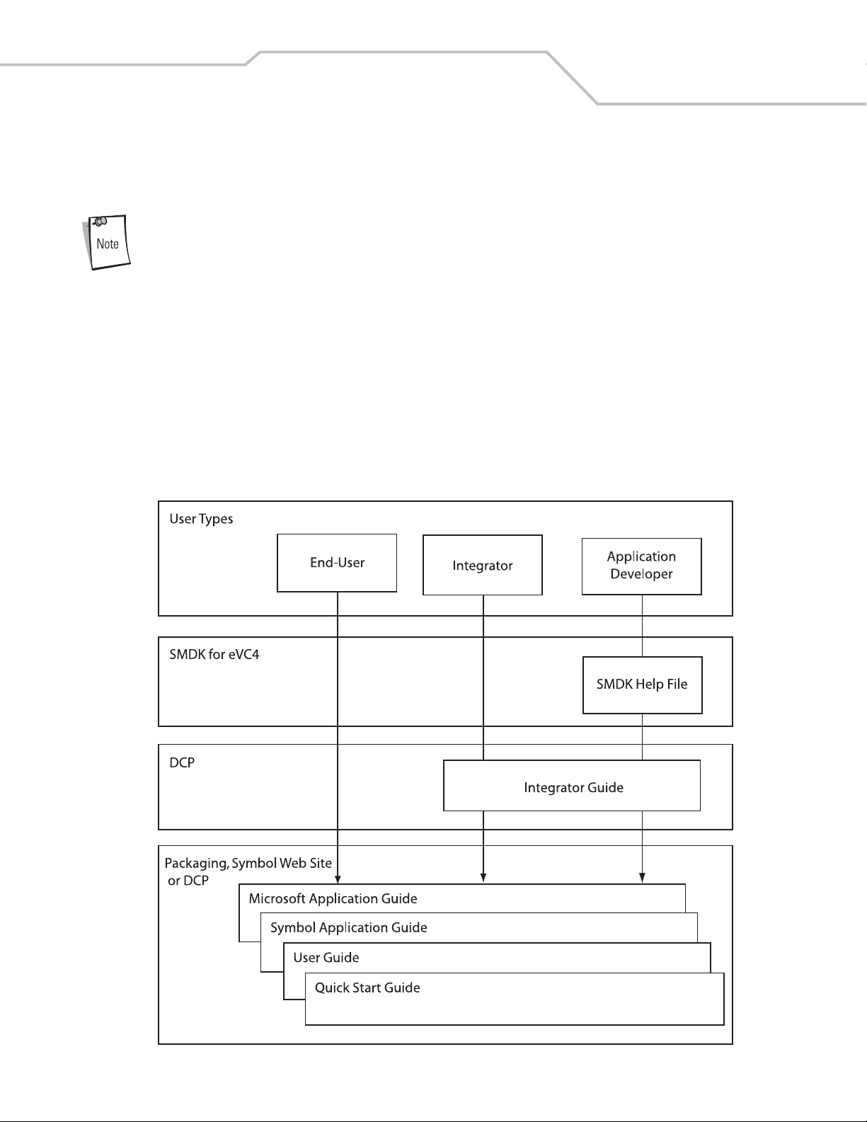
Documentation Set
The documentation set for the MC3000 is divided into guides that provide information for specific user needs.
• Microsoft Application Guide - describes how to use Microsoft developed applications.
• Symbol Application Guide - describes how to use Symbol developed applications.
• MC3000 User Guide - describes how to use the MC3000 mobile computer.
• MC3000 Integrator Guide - describes how to set up the MC3000 mobile computer and the accessories.
• SMDK Help File - provides API information for writing applications.
xiii
Page 16

MC3000 Integrator Guidexiv
Configurations
This guide covers the following configurations:
MC3000-R - color or monochrome display, 32MB/64MB or 64MB/64MB memory, laser scanner in rotating turret, Windows CE .NET
5.0 Core or Windows CE .NET 5.0 Professional Operating System.
MC3090-G - 802.11b/g/a radio, color or monochrome display, 32MB/64MB or 64MB/64MB memory, laser scanner or imager,
Windows CE .NET 5.0 Core or Windows CE .NET 5.0 Professional Operating system, optional Bluetooth radio.
MC3090-K - 802.11b/g/a radio, color display, 64MB/64MB memory, imager, Windows CE .NET 5.0 Professional Operating System,
audio and optional Bluetooth radio.
MC3090-R - 802.11b/g/a radio, optional Bluetooth radio, color or monochrome display, 32MB/64MB or 64MB/64MB memory, laser
scanner in rotating turret, Windows CE .NET 5.0 Core or Windows CE .NET 5.0 Professional Operating System, audio and optional
Bluetooth radio.
Chapter Descriptions
Topics covered in this guide are as follows:
• Chapter 1, Getting Started, describes the mobile computer’s physical characteristics, how to install and charge the batteries,
remove and replace the Strap/Door Assembly and how to start the mobile computer for the first time.
• Chapter 2, Accessories, describes the accessories available including cradles, cables and spare battery chargers. Accessory
set up and use is also provided.
• Chapter 3, ActiveSync, provides instructions on installing ActiveSync, setting up a partnership and synchronizing information
between the mobile computer and a host computer.
• Chapter 4, Software Installation on Development PC, provides instructions for installing the Symbol Mobility Developer Kit
for C (SMDK for C) and the Device Configuration Package (DCP) for MC3000 on the host computer.
• Chapter 5, Software Installation on Mobile Computer, provides information about installing software and files on the mobile
computer to enable the mobile computer to share information with the host device.
• Chapter 6, Creating/Loading Hex Images, describes how to install and use the Terminal Configuration Manager (TCM) to
customize flash file system partitions for the mobile computer.
• Chapter 7, Wireless Applications, describes how to configure the wireless connection and how the wireless LANs allow the
mobile computers to communicate wirelessly with a host device.
• Chapter 8, AirBEAM Smart, explains how to transfer specially-designed software packages between a host server and
Symbol mobile computers.
• Chapter 10, Maintenance & Troubleshooting, includes instructions on cleaning and storing the mobile computer, and
provides troubleshooting solutions for potential problems during mobile computer operation.
• Appendix A, Technical Specifications, includes a table listing the technical specifications for the mobile computer.
Page 17

Notational Conventions
The following conventions are used in this document:
• The term “mobile computer” refers to the Symbol MC3000.
• Italics are used to highlight the following:
• Chapters and sections in this and related documents
• Dialog box, window and screen names
• Drop-down list and list box names
• Check box and radio button names
• Icons on a screen.
• Bold text is used to highlight the following:
• Key names on a keypad
• Button names on a screen.
• Bullets (•) indicate:
• Action items
• Lists of alternatives
• Lists of required steps that are not necessarily sequential.
• Sequential lists (e.g., those that describe step-by-step procedures) appear as numbered lists.
xv
Related Documents and Software
The following documents provide more information about the MC3000 mobile computers.
• MC3000-K/R Quick Start Guide p/n 72-68902-xx
• MC3090-G Quick Start Guide, p/n 72-71347-xx
• MC3000 Licensing, Patent and Regulatory Information, p/n 72-68903-xx
• MC3000 User Guide, p/n 72E-68899-xx
• Symbol Application Guide for Symbol Devices, p/n 72-68901-xx
®
• Microsoft
• Symbol Mobility Developer Kit (SMDK) Help File, p/n 72E-38880-02
• Windows CE Platform SDK for MC3000c42a/b, available at:
http://devzone.symbol.com
• Symbol Mobility Developer Kit for C (SMDK for C), available at:
http://devzone.symbol.com
• Device Configuration Package for MC3000 (DCP for MC3000), available at:
http://devzone.symbol.com
• ActiveSync software, available at: http://www.microsoft.com.
For the latest version of this guide and all guides, go to: http://www.symbol.com/manuals.
Applications User Guide for Symbol Devices, p/n 72E-68197-xx
Page 18

MC3000 Integrator Guidexvi
Service Information
If an equipment problem occurs, contact the appropriate regional Symbol Support Center. See page xvi for contact information. Before
calling, have the model number, serial number and several bar code symbols at hand.
Call the Support Center from a phone near the scanning equipment so that the service person can try to talk through the problem. If
the equipment is found to be working properly and the problem is symbol readability, the Support Center will request samples of bar
codes for analysis at our plant.
If the problem cannot be solved over the phone, the equipment may need to be returned for servicing. If that is necessary, specific
directions will be provided.
Symbol Technologies is not responsible for any damages incurred during shipment if the approved shipping
container is not used. Shipping the units improperly can possibly void the warranty.
Symbol Support Center
For service information, warranty information or technical assistance contact or call the Symbol Support Center in:.
United States
Symbol Technologies, Inc.
One Symbol Plaza
Holtsville, New York 11742-1300
1-800-653-5350
United Kingdom
Symbol Technologies
Symbol Place
Winnersh Triangle, Berkshire RG41 5TP
United Kingdom
0800 328 2424 (Inside UK)
+44 118 945 7529 (Outside UK)
Australia
Symbol Technologies Pty. Ltd.
432 St. Kilda Road
Melbourne, Victoria 3004
1-800-672-906 (Inside Australia)
+61-3-9866-6044 (Outside Australia)
Denmark/Danmark
Symbol Technologies AS
Dr. Neergaardsvej 3
2970 Hørsholm
7020-1718 (Inside Denmark)
+45-7020-1718 (Outside Denmark)
Canada
Symbol Technologies Canada, Inc.
5180 Orbitor Drive
Mississauga, Ontario L4W 5L9
905-629-7226
Asia/Pacific
Symbol Technologies Asia, Inc.
230 Victoria Street #04-05
Bugis Junction Office Tower
Singapore 188024
337-6588 (Inside Singapore)
+65-337-6588 (Outside Singapore)
Austria/Österreich
Symbol Technologies Austria GmbH
Prinz-Eugen Strasse 70 / 2.Haus
1040 Vienna, Austria
01-5055794-0 (Inside Austria)
+43-1-5055794-0 (Outside Austria)
Europe/Mid-East Distributor Operations
Contact your local distributor or call
+44 118 945 7360
Page 19

xvii
Finland/Suomi
Oy Symbol Technologies
Kaupintie 8 A 6
FIN-00440 Helsinki, Finland
9 5407 580 (Inside Finland)
+358 9 5407 580 (Outside Finland)
Germany/Deutschland
Symbol Technologies GmbH
Waldstrasse 66
D-63128 Dietzenbach, Germany
6074-49020 (Inside Germany)
+49-6074-49020 (Outside Germany)
Latin America Sales Support
Latin America & The Caribbean
2730 University Drive
Coral Springs, Florida 33065
United States
+1.954.255.2610 (Outside US)
1-800-347-0178 (Inside US)
Fax: +1.954.340.9454
Netherlands/Nederland
Symbol Technologies
Kerkplein 2, 7051 CX
Postbus 24 7050 AA
Varsseveld, Netherlands
315-271700 (Inside Netherlands)
+31-315-271700 (Outside Netherlands)
South Africa
Symbol Technologies Africa Inc.
Block B2
Rutherford Estate
1 Scott Street
Waverly 2090 Johannesburg
Republic of South Africa
11-809 5311 (Inside South Africa)
+27-11-809 5311 (Outside South Africa)
France
Symbol Technologies France
Centre d'Affaire d'Antony
3 Rue de la Renaissance
92184 Antony Cedex, France
01-40-96-52-21 (Inside France)
+33-1-40-96-52-50 (Outside France)
Italy/Italia
Symbol Technologies Italia S.R.L.
Via Cristoforo Columbo, 49
20090 Trezzano S/N Navigilo
Milano, Italy
2-484441 (Inside Italy)
+39-02-484441 (Outside Italy)
Mexico/México
Symbol Technologies Mexico Ltd.
Boulevard Manuel Ávila Camacho # 24- 9 Piso
Col. Lomas de Chapultepec
México DF: CP 11000
Mexico City, DF, Mexico
5-520-1835 (Inside Mexico)
+52-5-520-1835 (Outside Mexico)
Norway/Norge
Symbol’s registered and mailing address:
Symbol Technologies Norway
Helsfyr Panorama
Innspurten 9
Oslo N-0663
Symbol’s repair depot and shipping address:
Symbol Technologies Norway
Enebakkveien 123
N-0680 OSLO, Norway
+47 2232 4375
Spain/España
Symbol Technologies S.L.
Avenida de Bruselas, 22
Edificio Sauce
Alcobendas, Madrid 28108
Spain
+913244000 (Inside Spain)
+34-9-1-320-39-09 (Outside Spain)
Page 20

MC3000 Integrator Guidexviii
Sweden/Sverige
“Letter” address:
Symbol Technologies AB
Box 1354
S-171 26 SOLNA
Sweden
Visit/shipping address:
Symbol Technologies AB
Solna Strandväg 78
S-171 54 SOLNA
Sweden
Switchboard: 08 445 29 00 (domestic)
Call Center: +46 8 445 29 29 (international)
Support E-Mail: Sweden.Support@se.symbol.com
If the Symbol product was purchased from a Symbol Business Partner, contact that Business Partner for service.
Page 21

Getting Started
Chapter Contents
Introduction . . . . . . . . . . . . . . . . . . . . . . . . . . . . . . . . . . . . . . . . . . . . . . . . . . . . . . . . . . . . . . . . . . . . . . . . . . . . .1-3
Unpacking the Mobile Computer . . . . . . . . . . . . . . . . . . . . . . . . . . . . . . . . . . . . . . . . . . . . . . . . . . . . . . . . . . . . .1-3
Accessories . . . . . . . . . . . . . . . . . . . . . . . . . . . . . . . . . . . . . . . . . . . . . . . . . . . . . . . . . . . . . . . . . . . . . . . . . . . . .1-3
Parts . . . . . . . . . . . . . . . . . . . . . . . . . . . . . . . . . . . . . . . . . . . . . . . . . . . . . . . . . . . . . . . . . . . . . . . . . . . . . . . . . . .1-5
Rotating Scan Turret . . . . . . . . . . . . . . . . . . . . . . . . . . . . . . . . . . . . . . . . . . . . . . . . . . . . . . . . . . . . . . . . . .1-6
Mobile Computer Startup. . . . . . . . . . . . . . . . . . . . . . . . . . . . . . . . . . . . . . . . . . . . . . . . . . . . . . . . . . . . . . . . . . .1-7
Install Main Battery . . . . . . . . . . . . . . . . . . . . . . . . . . . . . . . . . . . . . . . . . . . . . . . . . . . . . . . . . . . . . . . . . . .1-7
Battery Charging. . . . . . . . . . . . . . . . . . . . . . . . . . . . . . . . . . . . . . . . . . . . . . . . . . . . . . . . . . . . . . . . . . . . . . . . .1-10
Spare Battery Charging . . . . . . . . . . . . . . . . . . . . . . . . . . . . . . . . . . . . . . . . . . . . . . . . . . . . . . . . . . . . . . . . . . .1-11
Stylus . . . . . . . . . . . . . . . . . . . . . . . . . . . . . . . . . . . . . . . . . . . . . . . . . . . . . . . . . . . . . . . . . . . . . . . . . . . . . . . . .1-11
Starting the Mobile Computer . . . . . . . . . . . . . . . . . . . . . . . . . . . . . . . . . . . . . . . . . . . . . . . . . . . . . . . . . . . . . .1-12
Calibration Screen . . . . . . . . . . . . . . . . . . . . . . . . . . . . . . . . . . . . . . . . . . . . . . . . . . . . . . . . . . . . . . . . . . . 1-12
Demo Window . . . . . . . . . . . . . . . . . . . . . . . . . . . . . . . . . . . . . . . . . . . . . . . . . . . . . . . . . . . . . . . . . . . . . .1-13
Resetting the Mobile Computer. . . . . . . . . . . . . . . . . . . . . . . . . . . . . . . . . . . . . . . . . . . . . . . . . . . . . . . . . . . . .1-14
Performing a Warm Boot . . . . . . . . . . . . . . . . . . . . . . . . . . . . . . . . . . . . . . . . . . . . . . . . . . . . . . . . . . . . . .1-14
Performing a Cold Boot . . . . . . . . . . . . . . . . . . . . . . . . . . . . . . . . . . . . . . . . . . . . . . . . . . . . . . . . . . . . . . .1-14
Waking the Mobile Computer . . . . . . . . . . . . . . . . . . . . . . . . . . . . . . . . . . . . . . . . . . . . . . . . . . . . . . . . . . . . . .1-15
Main Battery Removal . . . . . . . . . . . . . . . . . . . . . . . . . . . . . . . . . . . . . . . . . . . . . . . . . . . . . . . . . . . . . . . . . . . .1-16
Strap/Door Assembly Removal and Replacement. . . . . . . . . . . . . . . . . . . . . . . . . . . . . . . . . . . . . . . . . . . . . . .1-18
Strap/Door Assembly Removal and Replacement (MC3090-G) . . . . . . . . . . . . . . . . . . . . . . . . . . . . . . . . . . . .1-19
File System Directory Structure . . . . . . . . . . . . . . . . . . . . . . . . . . . . . . . . . . . . . . . . . . . . . . . . . . . . . . . . . . . . .1-20
Flash Storage . . . . . . . . . . . . . . . . . . . . . . . . . . . . . . . . . . . . . . . . . . . . . . . . . . . . . . . . . . . . . . . . . . . . . . . . . . .1-20
Launching Applications . . . . . . . . . . . . . . . . . . . . . . . . . . . . . . . . . . . . . . . . . . . . . . . . . . . . . . . . . . . . . . . . . . .1-20
Page 22

MC3000 Integrator Guide1-2
Page 23

Getting Started 1-3
Introduction
This chapter describes the mobile computer’s physical characteristics, how to install and charge the batteries, how to remove and
replace the Strap/Door Assembly and how to start the mobile computer for the first time.
Unpacking the Mobile Computer
Carefully remove all protective material from around the mobile computer and save the shipping container for later storage and
shipping. Verify that the equipment listed below is included:
• MC3000 mobile computer
• Strap/Door Assembly, attached to the mobile computer
•Stylus
• Regulatory Guide
• Quick Start Guide (poster).
Depending on the configuration ordered, the mobile computer shipping container or additional shipping container may include:
• Standard Battery (lithium-polymer)
• Extended Life Battery (lithium-ion)
• Cable(s)
• Power Supply
• Cradles.
Inspect the equipment for damage. If any equipment is missing or damaged, contact the Symbol Technologies Support Center
immediately. See page xvi for contact information.
Accessories
Table 1-1 lists the MC3000 accessories.
Table 1-1. MC3000 Accessories
Accessory Description
Single Slot Serial/USB Cradle Charges the mobile computer main battery and a spare battery, and synchronizes the mobile computer with
a host computer through either a serial or USB connection.
Four Slot Charge Only Cradle Charges up to four mobile computers.
Four Slot Ethernet Cradle Charges up to four mobile computers and provides Ethernet communications.
Four Slot Spare Battery Charger Charges up to four mobile computer spare batteries.
Power Supply Country specific and accessory specific, power supply.
USB Client Charge Cable Provides USB client communication capabilities and charges the mobile computer.
Serial (RS232) Charge Cable Provides RS232 communication capabilities and charges the mobile computer.
O’Neil Printer Cable Provides printer specific communication capabilities (provided by O’Neil).
Zebra Printer Cable Provides printer specific communication capabilities (provided by Zebra).
Monarch Printer Cable Provides printer specific communication capabilities (provided by Monarch).
Single Slot Cradle RS232 Cable Provides serial host communication capabilities and charges the mobile computer.
Single Slot Cradle USB Cable Provides USB communication capabilities and charges the mobile computer.
MC3000 Universal Battery Charger Adapter (UBC) Adapts the UBC for use with MC3000 batteries.
Page 24

MC3000 Integrator Guide1-4
Table 1-1. MC3000 Accessories (Continued)
Accessory Description
Stylus Performs pen and mouse functions.
Plastic Holster Provides a clip on holder for the mobile computer.
Fabric Holster Provides a soft, clip on holder and a shoulder strap for the mobile computer.
Symbol Mobility Developer Kit for C A development tool used to create native C and C++ applications for all Symbol mobile computers
running the Microsoft Windows CE operating system. Available at: http://devzone.symbol.com.
Device Configuration Package (DCP) for MC3000 A development tool used to create and download hex images that represent flash partitions to the mobile
computer. Available at: http://devzone.symbol.com.
Page 25
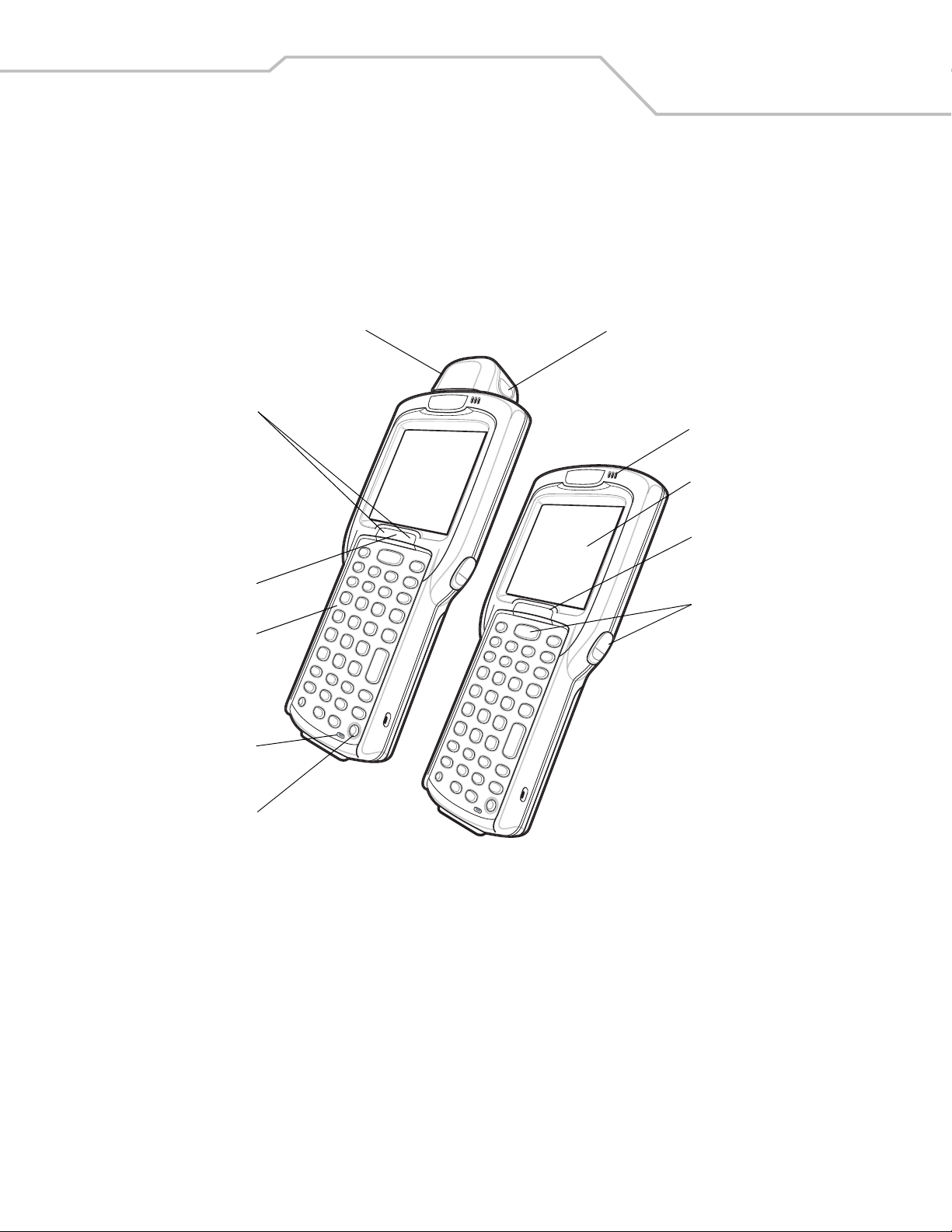
Getting Started 1-5
Parts
There are three versions of the MC3000 mobile computers, the MC3000 1D/2D Imager (MC3000-K or MC3090-K), the MC3000 Laser
with Rotating Scan Turret (MC3000-R or MC3090-R) and the MC3090 Gun (MC3090-G). For more information on the Rotating Scan
Turret, see Figure 1-3 on page 1-6.
Scan LED
Indicators
(red/green)
Charge LED
Indicator
(amber)
Keypad
Microphone
(optional)
Rotating
Scan Turret
Scan LED Indicator
(red/green)
Beeper or
Receiver (optional)
Screen
Indicator LED
Bar
Scan Buttons
Power
MC3000-R
MC3000-K
Figure 1-1. MC3000 Imager (MC3000-K) and MC3000 Laser (MC3000-R) Mobile Computers (front view)
Page 26
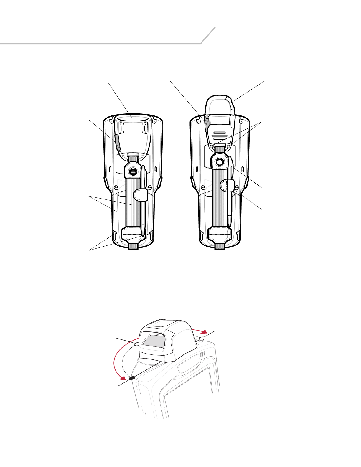
MC3000 Integrator Guide1-6
Headset Jack
Scan Window
(optional)
Scan Window
Headset Jack
(optional)
Strap/Door
Assembly
Latches
MC3000-K
MC3000-R
Strap/Door
Assembly
Screws
Stylus
Stylus
Holder
Figure 1-2. MC3000 Imager (MC3000-K) and MC3000 Laser (MC3000-R) Mobile Computers (back view)
Rotating Scan Turret
The MC3000-R mobile computer features a Rotating Scan Turret with three position stops. This feature offers greater scanning
flexiblilty.
Position Stop
Position Stop
Position Stop
Figure 1-3. Rotating Scan Turret
Page 27
Getting Started 1-7
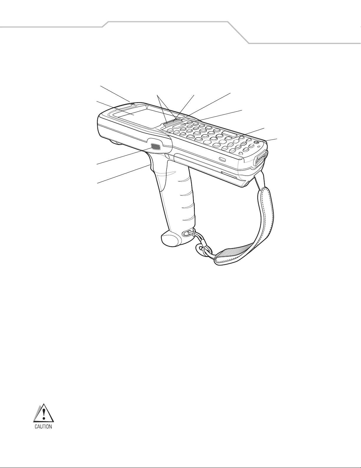
Display
Scan LED
Indicator
(red/green)
Tr ig ge r
Beeper
Scan LED
Indicators
(red/green)
Charge LED
Indicator
(amber)
Indicator LED Bar
Scan Button
Keypad
Power
Figure 1-4. MC3090-G Mobile Computer
Mobile Computer Startup
To start using the mobile computer:
• Install the main battery.
• Charge the main battery and the backup battery.
• Start the mobile computer.
Install Main Battery
If the main battery is charged, the mobile computer can be used immediately. If the main battery is not charged, see Battery Charging
on page 1-10. To remove the main battery, see Main Battery Removal on page 1-16.
To install the main battery:
1. Rotate the latches to the open position.
Do not lift up on the Latches when removing the Strap/Door Assembly. Lift up on the Hand Strap only.
2. Pull on the strap to lift the Strap/Door Assembly off, bottom first.
Page 28
MC3000 Integrator Guide1-8
3. Insert the battery into the slot, bottom first and press the battery gently into the slot. The battery clip locks the battery into
place.
4. With the latches in the open position, replace the Strap/Door Assembly, top first and press to close.
5. Rotate the latches (to the lock position) to lock the Strap/Door Assembly in place.
Latches
Strap/Door
Assembly
Hand Strap
Battery Clip
Battery Slot
Battery
Figure 1-5. Main Battery Installation
Page 29
Latches
Getting Started 1-9
Hand Strap
Battery
Strap/Door
Assembly
Figure 1-6. Main Battery Installation (MC3090-G)
Strap/Door
Assembly
Page 30

MC3000 Integrator Guide1-10
Battery Charging
Use the mobile computer cradles, cables and spare battery chargers to charge the mobile computer main battery.
The main battery can be charged before insertion into the mobile computer or after it is installed. There are two main batteries for
the MC3000, the Standard Battery and the Extended Life Battery. Either battery can be used, but the Extended Life Battery requires
a different Strap/Door Assembly. Use one of the spare battery chargers to charge the main battery (out of the mobile computer) or
one of the cradles to charge the main battery while it is installed in the mobile computer.
Before using the mobile computer for the first time, fully charge the main battery. When the main battery is fully charged, the amber
Charge LED Indicator remains lit. For more information see Table 1-2 on page 1-11. Charge time for the Standard Battery is usually
less than four hours and charge time for the Extended Life Battery is usually less than six hours.
The mobile computer is equipped with a memory backup battery which automatically charges from the fully-charged main battery.
When the mobile computer is used for the first time, the backup battery requires approximately 15 hours to fully charge. This is also
true any time the backup battery is discharged which occurs when the main battery is removed for several hours. The backup battery
retains data in memory for at least 30 minutes after the mobile computer main battery is removed. When the mobile computer reaches
very low battery state, the combination of main battery and backup battery retains data in memory for at least 72 hours.
Do not remove the main battery within the first 15 hours of use. If the main battery is removed before the backup battery
is fully charged, data may be lost.
Batteries must be charged within the 32° to 104° F (0° to +40° C) ambient temperature range.
The following accessories can be used to charge the batteries:
• Cradles (and a power supply):
• Single Slot Serial/USB Cradle
• Four Slot Cradles.
• Cables (and a power supply):
• USB Client Charge Cable
• Serial (RS232) Charge Cable.
• Spare Battery Chargers (and a power supply):
• Single Slot Serial/USB Cradle
• Four Slot Spare Battery Charger
• Universal Battery Charger (UBC) Adapter.
To charge the mobile computer using the cradles:
1. Insert the mobile computer into a cradle. See Chapter 2, Accessories for accessory information.
2. The mobile computer starts to charge automatically. The amber Charge LED Indicator indicates the charge status. See Table
1-2 on page 1-11 for charging indications.
To charge the mobile computer using the cables:
1. Connect the MC3000 Communication/Charge Cable to the appropriate power source and connect to the mobile computer.
See Chapter 2, Accessories for accessory setup.
2. The mobile computer starts to charge automatically. The amber Charge LED Indicator indicates the charge status. See Table
1-2 on page 1-11 for charging indications.
Page 31

Table 1-2. Mobile Computer LED Charge Indicators
LED Indication
Off Mobile computer not placed correctly in the cradle; cable not connected correctly; charger is not powered.
Fast Blinking Amber Error in charging; check placement of the mobile computer.
Slow Blinking Amber Mobile computer is charging.
Solid Amber Charging complete.
Note: When the battery is initially inserted in the mobile computer, the amber LED flashes once if the battery
power is low or the battery is not fully inserted.
Spare Battery Charging
There are three accessories that can be used to charge a spare battery:
• Single Slot Serial/USB Cradle
• Four Slot Spare Battery Charger
•UBC Adapter.
Getting Started 1-11
To charge a spare battery:
1. Connect the charging accessory to the appropriate power source. See Chapter 2, Accessories for setup instructions.
2. Insert the spare battery into the spare battery charging slot and gently press down on the battery to ensure proper contact.
The battery starts to charge automatically. The charge LED Indicator lights to indicates the charge status. See Chapter 2, Accessories
for charging indications. The Standard Battery usually fully charges in less than four hours and the Extended Life Battery usually fully
charges in less than six hours.
Stylus
Use the stylus to select items and enter information on the screen. The stylus functions as a pen and a mouse. Tap the touch screen
once with the stylus to select options and open menu items.
To remove the stylus, slide the stylus out of the stylus holder. To store the stylus, push the stylus back into the stylus holder.
Page 32

MC3000 Integrator Guide1-12
Starting the Mobile Computer
When the mobile computer is powered on for the first time, it initializes. The Symbol Splash screen appears for a short period of time,
followed by the Calibration screen.
Figure 1-7. Symbol Splash Screen
After the calibration procedure is performed the factory default settings launch the Demo window. Application specific shells may
provide application specific windows instead of the Demo window. These screens also appear when a cold boot is performed.
If the mobile computer does not power on, see Resetting the Mobile Computer on page 1-14.
Calibration Screen
Use the Calibration screen to align the touch screen:
1. Remove the stylus from the stylus holder.
2. Carefully press and briefly hold the tip of stylus on the center of the Calibration screen target. Repeat the procedure as the
target moves and stops at different locations on the screen. This enters the new calibration settings.
Calibration Screen Confirm Calibration Resave
Screen
Figure 1-8. Calibration Screen
3. Once all of the new calibration settings are input, the Confirm Calibration Resave screen appears. Tap the screen within 30
seconds to save the new calibration settings or allow the 30 second timer to expire and the new calibration settings are not
saved.
Page 33

Getting Started 1-13
Demo Window
The Demo window is the factory default menu. On initial power up (or on a warm or cold boot) the Demo window appears. These
sample/demo applications are intended to be used by application developers as application development examples. These
applications were not developed to support end users. Refer to the Symbol Application Guide for information about the Demo window
applications.
Figure 1-9. Demo Window
Page 34

MC3000 Integrator Guide1-14
Resetting the Mobile Computer
If the mobile computer stops responding to input, reset it. There are two reset functions, warm boot and cold boot. A warm boot
restarts the mobile computer by closing all running programs. All data that is not saved is lost.
A cold boot also restarts the mobile computer, but erases all stored records and entries from RAM. In addition it returns formats,
preferences and other settings to the factory default settings.
Perform a warm boot first. This restarts the mobile computer and saves all stored records and entries. If the mobile computer still
does not respond, perform a cold boot.
Performing a Warm Boot
To perform a warm boot:
1. Press and simultaneously hold 7, 9 and Power. Do not hold down any other keys or buttons.
2. As the mobile computer initializes MC3000 Demo window appears.
Files that remain open during a warm boot may not be retained.
Performing a Cold Boot
A cold boot restarts the mobile computer and erases all user stored records and entries from RAM. Never perform a cold boot unless
a warm boot does not solve the problem.
Cold boot resets the mobile computer, to the default settings. All added applications and all stored data are removed. Do
not cold boot without support desk approval.
Any data previously synchronized with a computer can be restored during the next ActiveSync operation. See
Chapter 3, ActiveSync for detailed ActiveSync instructions.
To perform a cold boot:
1. Press and simultaneously hold the 1, 9 and Power keys. Do not hold down any other keys or buttons. As the mobile computer
initializes, the Symbol Splash window, Figure 1-7 on page 1-12, appears for about a minute.
2. Calibrate the touch screen. See Calibration Screen on page 1-12 to align the touch screen.
Page 35

Getting Started 1-15
Waking the Mobile Computer
The wakeup conditions are configurable and the current factory default settings are subject to change/update. The mobile computer
wakeup configuration is set in the registry file. Table 1-3 lists the default wakeup conditions settings.
Table 1-3. Default Wakeup Conditions
Status Description Conditions for wakeup
Power Off When the mobile computer goes into
suspend mode by pressing P
these actions wake the mobile
computer.
Auto Off When the mobile computer goes into
suspend mode by an automatic
power-off function, these actions
wake the mobile computer.
ower,
1. Power button is pressed.
2. AC power added or removed.
Any key or the Scan Button is pressed.
Real Time Clock set to wake up.
1. Power button is pressed.
2. AC power added or removed.
Any key or the Scan Button is pressed.
Real Time Clock set to wake up.
Page 36

MC3000 Integrator Guide1-16
Main Battery Removal
Before removing the main battery, press the red Power button to turn off the screen and set the mobile computer to suspend mode.
To remove the main battery:
1. Rotate the latches to the open position.
Do not lift up on the Latches when removing the Strap/Door Assembly. Lift up on the Hand Strap only.
2. Lift the Hand Strap to lift the Strap/Door Assembly off, bottom first.
3. Release battery:
a. On the MC3000-K/R, release the battery clip (at the top of the battery) and lift the battery out top first.
b. On the MC3090-G, pull the battery pull tab to unclip the battery and lift the battery out top first. If the battery does not
have a pull tab, use the stylus to unclip the battery and then lift the battery.
Latches
Strap/Door
Assembly
Battery
Battery Clip
Figure 1-10. Main Battery Removal (MC3000-K/R)
Hand Strap
Page 37

Getting Started 1-17
Battery
Latches
Battery with Pull Tab
Strap/Door
Assembly
Battery Pull Tab
Battery without Pull Tab
Figure 1-11. Main Battery Removal (MC3090-G)
Page 38

MC3000 Integrator Guide1-18
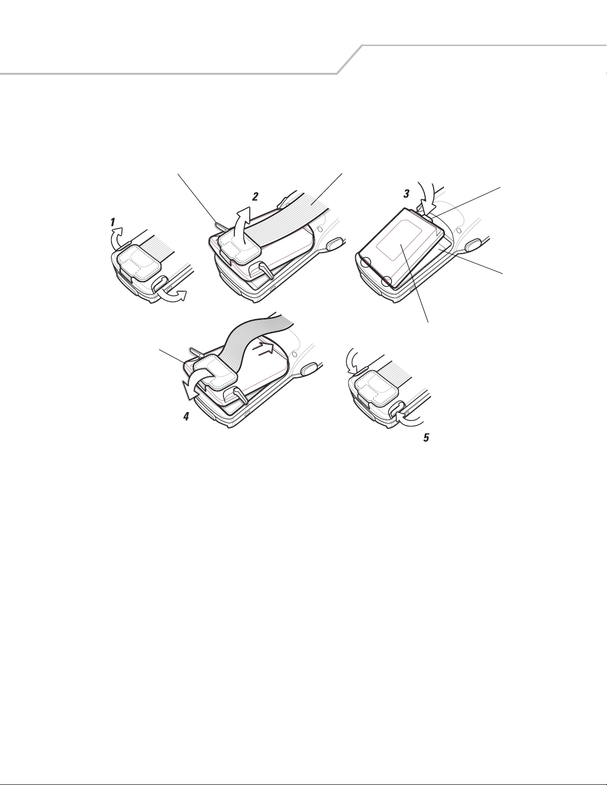
Strap/Door Assembly Removal and Replacement
The Strap/Door Assembly consists of a hand strap and the battery door. There are two versions of this assembly, one for the Standard
Battery and one for the Extended Life Battery. Before removing the Strap/Door Assembly, press the red Power button to turn off the
screen and set the mobile computer to suspend mode.
To remove the Strap/Door Assembly:
1. Rotate the latches to the open position.
Do not lift up on the Latches when removing the Strap/Door Assembly. Lift up on the Hand Strap only.
2. Lift the Hand Strap to lift the Strap/Door Assembly off, bottom first.
3. Use a #00 Phillips screwdriver to remove the screws.
4. Lift the mounting clip.
5. Slide the mounting clip out of the strap loop.
Reverse the procedure to replace the Strap/Door Assembly.
Latches
#00 Phillips
Screwdriver
Screws
Strap/Door
Assembly
Mounting
Clip
Strap Loop
Hand Strap
Mounting
Clip
Figure 1-12. Strap/Door Removal and Replacement
Page 39
Getting Started 1-19
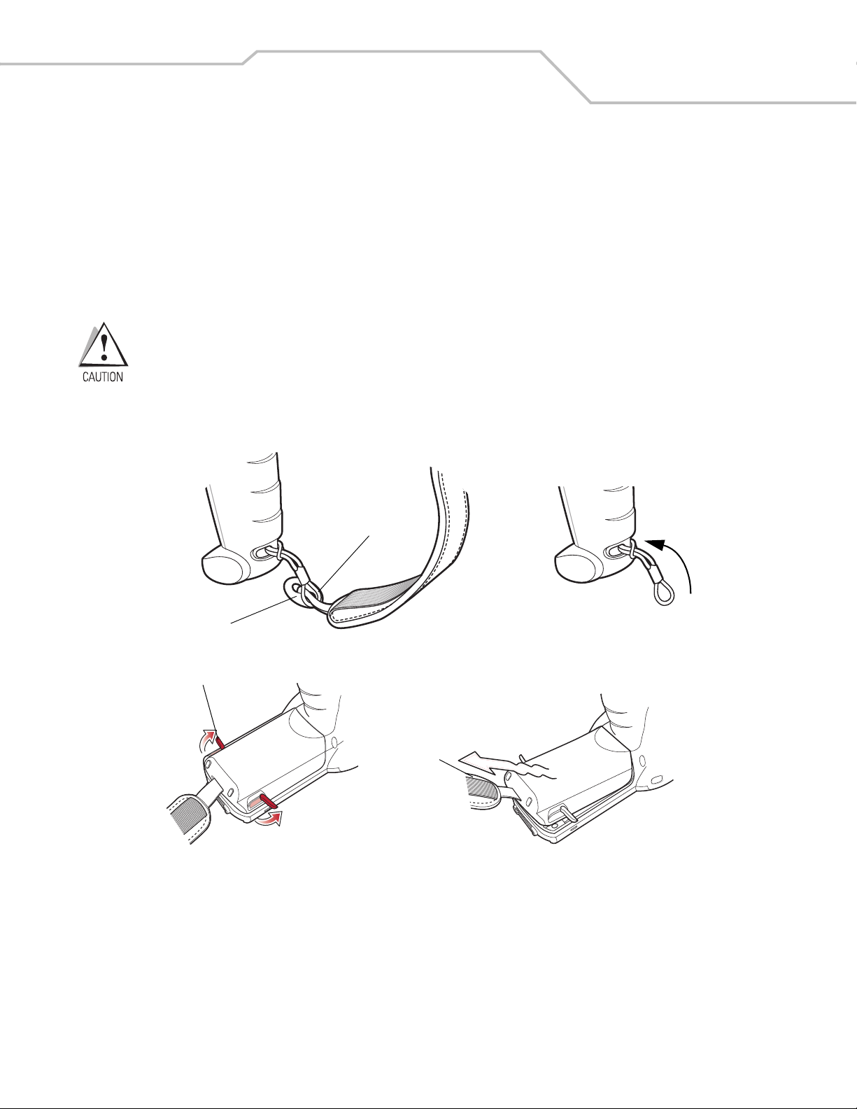
Strap/Door Assembly Removal and Replacement (MC3090-G)
The Strap/Door Assembly consists of a hand strap and the battery door. Before removing the Strap/Door Assembly, press the red
Power button to turn off the screen and set the mobile computer to suspend mode.
To remove the Strap/Door Assembly:
1. Slip the button through the loop.
2. Remove loop section from handle.
3. Rotate the latches to the open position.
Do not lift up on the latches when removing the Strap/Door Assembly. Lift up on the Hand Strap only.
4. Lift the Hand Strap to lift the Strap/Door Assembly off, bottom first.
Reverse the procedure to replace the Strap/Door Assembly.
Button
Latches
Loop
Strap/Door
Assembly
Figure 1-13. Strap/Door Removal and Replacement (MC3090-G)
Page 40

MC3000 Integrator Guide1-20
File System Directory Structure
The mobile computer directory structure displays all of the file folders. The pre-installed folders are in flash file system memory and
optional removable storage devices (SD storage cards).
Figure 1-14. Mobile Computer Directory Structure
• Application and Platform folders are located in flash file system memory.
• The Windows, Program Files, profiles, and My Documents folders are composites, RAM based folders generated from ROM.
• The Network folder is a link to file systems mapped using the network re-director. The files do not physically reside on the
mobile computer.
• The Tem p and Recycled folders typically contain RAM based files.
All files copied to the RAM based folders are lost after a cold boot.
Flash Storage
In addition to the RAM based storage the mobile computer is also equipped with a non-volatile flash based storage area which can
store data (partitions) that can not be corrupted by a cold boot. See Flash Storage on page 6-18 for a detailed discussion.
Launching Applications
The Application/Startup folder is used to launch programs automatically when the mobile computer is powered on or after a warm
or cold boot.
The Windows/Startup folder is not supported.
There are two ways to launch programs automatically:
1. Place the executable in the Startup folder (located in the Application folder).
2. Place a .run file in the Startup folder. A .run file is a simple text file that contains the path to an application as well as the
name of the application to run.
Refer to the SMDK Help File included with the SMDK for more information on the Startup folder.
Page 41

Accessories
Chapter Contents
Introduction . . . . . . . . . . . . . . . . . . . . . . . . . . . . . . . . . . . . . . . . . . . . . . . . . . . . . . . . . . . . . . . . . . . . . . . . . . . . .2-3
Cradles . . . . . . . . . . . . . . . . . . . . . . . . . . . . . . . . . . . . . . . . . . . . . . . . . . . . . . . . . . . . . . . . . . . . . . . . . . . . .2-3
Spare Battery Chargers . . . . . . . . . . . . . . . . . . . . . . . . . . . . . . . . . . . . . . . . . . . . . . . . . . . . . . . . . . . . . . . .2-3
Cables. . . . . . . . . . . . . . . . . . . . . . . . . . . . . . . . . . . . . . . . . . . . . . . . . . . . . . . . . . . . . . . . . . . . . . . . . . . . . . 2-3
SD Card. . . . . . . . . . . . . . . . . . . . . . . . . . . . . . . . . . . . . . . . . . . . . . . . . . . . . . . . . . . . . . . . . . . . . . . . . . . . .2-3
Single Slot Serial/USB Cradle . . . . . . . . . . . . . . . . . . . . . . . . . . . . . . . . . . . . . . . . . . . . . . . . . . . . . . . . . . . . . . .2-4
Setup . . . . . . . . . . . . . . . . . . . . . . . . . . . . . . . . . . . . . . . . . . . . . . . . . . . . . . . . . . . . . . . . . . . . . . . . . . . . . .2-4
Battery Charging. . . . . . . . . . . . . . . . . . . . . . . . . . . . . . . . . . . . . . . . . . . . . . . . . . . . . . . . . . . . . . . . . . . . . .2-5
LED Charge Indications . . . . . . . . . . . . . . . . . . . . . . . . . . . . . . . . . . . . . . . . . . . . . . . . . . . . . . . . . . . . . . . .2-6
Communication Setup . . . . . . . . . . . . . . . . . . . . . . . . . . . . . . . . . . . . . . . . . . . . . . . . . . . . . . . . . . . . . . . . .2-6
Four Slot Charge Only Cradle . . . . . . . . . . . . . . . . . . . . . . . . . . . . . . . . . . . . . . . . . . . . . . . . . . . . . . . . . . . . . . . .2-7
Setup . . . . . . . . . . . . . . . . . . . . . . . . . . . . . . . . . . . . . . . . . . . . . . . . . . . . . . . . . . . . . . . . . . . . . . . . . . . . . .2-7
Battery Charging. . . . . . . . . . . . . . . . . . . . . . . . . . . . . . . . . . . . . . . . . . . . . . . . . . . . . . . . . . . . . . . . . . . . . .2-8
Power LED . . . . . . . . . . . . . . . . . . . . . . . . . . . . . . . . . . . . . . . . . . . . . . . . . . . . . . . . . . . . . . . . . . . . . . . . . .2-8
LED Charge Indications . . . . . . . . . . . . . . . . . . . . . . . . . . . . . . . . . . . . . . . . . . . . . . . . . . . . . . . . . . . . . . . .2-8
Four Slot Ethernet Cradle . . . . . . . . . . . . . . . . . . . . . . . . . . . . . . . . . . . . . . . . . . . . . . . . . . . . . . . . . . . . . . . . . . .2-9
Setup . . . . . . . . . . . . . . . . . . . . . . . . . . . . . . . . . . . . . . . . . . . . . . . . . . . . . . . . . . . . . . . . . . . . . . . . . . . . . .2-9
Ethernet Cradle Drivers . . . . . . . . . . . . . . . . . . . . . . . . . . . . . . . . . . . . . . . . . . . . . . . . . . . . . . . . . . . . . . . .2-9
Charging and Communication . . . . . . . . . . . . . . . . . . . . . . . . . . . . . . . . . . . . . . . . . . . . . . . . . . . . . . . . . . 2-10
LED Charge Indications . . . . . . . . . . . . . . . . . . . . . . . . . . . . . . . . . . . . . . . . . . . . . . . . . . . . . . . . . . . . . . .2-10
Speed LED . . . . . . . . . . . . . . . . . . . . . . . . . . . . . . . . . . . . . . . . . . . . . . . . . . . . . . . . . . . . . . . . . . . . . . . . .2-10
Link LED . . . . . . . . . . . . . . . . . . . . . . . . . . . . . . . . . . . . . . . . . . . . . . . . . . . . . . . . . . . . . . . . . . . . . . . . . . .2-10
Daisychaining Ethernet Cradles. . . . . . . . . . . . . . . . . . . . . . . . . . . . . . . . . . . . . . . . . . . . . . . . . . . . . . . . .2-11
Bandwidth Considerations when Daisychaining. . . . . . . . . . . . . . . . . . . . . . . . . . . . . . . . . . . . . . . . 2-11
Four Slot Spare Battery Charger . . . . . . . . . . . . . . . . . . . . . . . . . . . . . . . . . . . . . . . . . . . . . . . . . . . . . . . . . . . .2-14
Page 42

MC3000 Integrator Guide2-2
Setup. . . . . . . . . . . . . . . . . . . . . . . . . . . . . . . . . . . . . . . . . . . . . . . . . . . . . . . . . . . . . . . . . . . . . . . . . . . . . .2-14
Spare Battery Charging . . . . . . . . . . . . . . . . . . . . . . . . . . . . . . . . . . . . . . . . . . . . . . . . . . . . . . . . . . . . . . .2-15
LED Charge Indications. . . . . . . . . . . . . . . . . . . . . . . . . . . . . . . . . . . . . . . . . . . . . . . . . . . . . . . . . . . . . . . .2-15
Cables . . . . . . . . . . . . . . . . . . . . . . . . . . . . . . . . . . . . . . . . . . . . . . . . . . . . . . . . . . . . . . . . . . . . . . . . . . . . . . . . .2-16
Setup. . . . . . . . . . . . . . . . . . . . . . . . . . . . . . . . . . . . . . . . . . . . . . . . . . . . . . . . . . . . . . . . . . . . . . . . . . . . . .2-17
Battery Charging. . . . . . . . . . . . . . . . . . . . . . . . . . . . . . . . . . . . . . . . . . . . . . . . . . . . . . . . . . . . . . . . . . . . .2-17
LED Charge Indications. . . . . . . . . . . . . . . . . . . . . . . . . . . . . . . . . . . . . . . . . . . . . . . . . . . . . . . . . . . . . . . .2-17
Communication Setup . . . . . . . . . . . . . . . . . . . . . . . . . . . . . . . . . . . . . . . . . . . . . . . . . . . . . . . . . . . . . . . .2-17
Universal Battery Charger (UBC) Adapter . . . . . . . . . . . . . . . . . . . . . . . . . . . . . . . . . . . . . . . . . . . . . . . . . . . . .2-18
Setup. . . . . . . . . . . . . . . . . . . . . . . . . . . . . . . . . . . . . . . . . . . . . . . . . . . . . . . . . . . . . . . . . . . . . . . . . . . . . .2-18
Spare Battery Charging . . . . . . . . . . . . . . . . . . . . . . . . . . . . . . . . . . . . . . . . . . . . . . . . . . . . . . . . . . . . . . .2-18
UBC Adapter LED Charge Indications. . . . . . . . . . . . . . . . . . . . . . . . . . . . . . . . . . . . . . . . . . . . . . . . . . . . .2-19
Secure Device Card. . . . . . . . . . . . . . . . . . . . . . . . . . . . . . . . . . . . . . . . . . . . . . . . . . . . . . . . . . . . . . . . . . . . . . .2-20
Copy Files onto the SD Card. . . . . . . . . . . . . . . . . . . . . . . . . . . . . . . . . . . . . . . . . . . . . . . . . . . . . . . . . . . .2-21
Delete a File From The SD Card . . . . . . . . . . . . . . . . . . . . . . . . . . . . . . . . . . . . . . . . . . . . . . . . . . . . . . . . .2-22
Format an SD Card . . . . . . . . . . . . . . . . . . . . . . . . . . . . . . . . . . . . . . . . . . . . . . . . . . . . . . . . . . . . . . . . . . .2-23
Serial/USB Communication . . . . . . . . . . . . . . . . . . . . . . . . . . . . . . . . . . . . . . . . . . . . . . . . . . . . . . . . . . . . . . . .2-28
Installing Serial/USB Communication Software . . . . . . . . . . . . . . . . . . . . . . . . . . . . . . . . . . . . . . . . . . . . . . . .2-28
Communication Setup. . . . . . . . . . . . . . . . . . . . . . . . . . . . . . . . . . . . . . . . . . . . . . . . . . . . . . . . . . . . . . . . . . . . .2-28
Serial Communication Setup . . . . . . . . . . . . . . . . . . . . . . . . . . . . . . . . . . . . . . . . . . . . . . . . . . . . . . . . . . .2-29
Serial Connection Setup. . . . . . . . . . . . . . . . . . . . . . . . . . . . . . . . . . . . . . . . . . . . . . . . . . . . . . . . . . .2-29
USB Connection Setup . . . . . . . . . . . . . . . . . . . . . . . . . . . . . . . . . . . . . . . . . . . . . . . . . . . . . . . . . . . . . . . .2-31
Cradle/Cable Setup . . . . . . . . . . . . . . . . . . . . . . . . . . . . . . . . . . . . . . . . . . . . . . . . . . . . . . . . . . . . . . . . . .2-32
Page 43

Accessories 2-3
Introduction
The MC3000 accessories provide a variety of product support capabilities. Accessories include cradles, cables, spare battery chargers
and SD cards.
Cradles
• Single Slot Serial/USB cradle charges the mobile computer main battery and/or a spare battery. It also synchronizes the
mobile computer with a host computer through either a serial or a USB connection.
• Four Slot Charge Only cradle charges up to four mobile computers.
• Four Slot Ethernet cradle charges up to four mobile computers and provides Ethernet communication capability.
Spare Battery Chargers
• Four Slot Spare Battery Charger charges up to four MC3000 spare batteries.
• UBC Adapter adapts the UBC2000 for use with the MC3000 spare batteries.
Cables
The cables snap on to the mobile computer and are used to connect external devices to the mobile computer.
• USB client charge cable
• Serial (RS232) charge cable
• O’Neil printer cable (provided by O’Neil)
• Zebra printer cable (provided by Zebra)
• Monarch printer cable (provided by Monarch).
SD Card
The SD card provides additional storage capacity for the mobile computer.
Page 44

MC3000 Integrator Guide2-4
Single Slot Serial/USB Cradle
This section describes how to set up and use the Single Slot Serial/USB cradle. For cradle setup, see Figure 2-2. For communications
setup procedures, see USB Connection Setup on page 2-32 and/or Serial Communication Setup on page 2-30.
The Single Slot Serial/USB cradle:
• Provides 5.4VDC power for operating the mobile computer, charging the battery and charging a spare battery.
• Provides a serial port and a USB port (mini AB receptacle) for data communication between the mobile computer and a host
computer or other serial devices (e.g., a printer).
• Synchronizes information between the mobile computer and a host computer. With customized or third party software, it can
also synchronize the mobile computer with corporate databases.
• Provides serial connection through the serial pass-through port for communication with a serial device, such as a host
computer. For communication setup procedures, see Serial Communication Setup on page 2-30.
• Provides USB connection through the USB pass-through port for communication with a USB device, such as a host computer.
For communication setup procedures, see USB Connection Setup on page 2-32.
Use only a Symbol approved power supply output rated 12 VDC and minimum 3.3 A. Use of an alternative
power supply will void the product warranty and may cause product damage. See the MC3000 User Guide for
the power supply regulatory compliance statement.
Setup
The cradle requires a dedicated port on the host computer. Select either serial or USB for communications, do not connect
the cradle to both serial and USB ports.
Serial Port
USB Port
USB Port
Serial Port
Power Port
DC Cable
USB Cable
Serial Cable
AC Line Cord
Power Supply
Figure 2-1. Single Slot Serial/USB Cradle Setup
Page 45
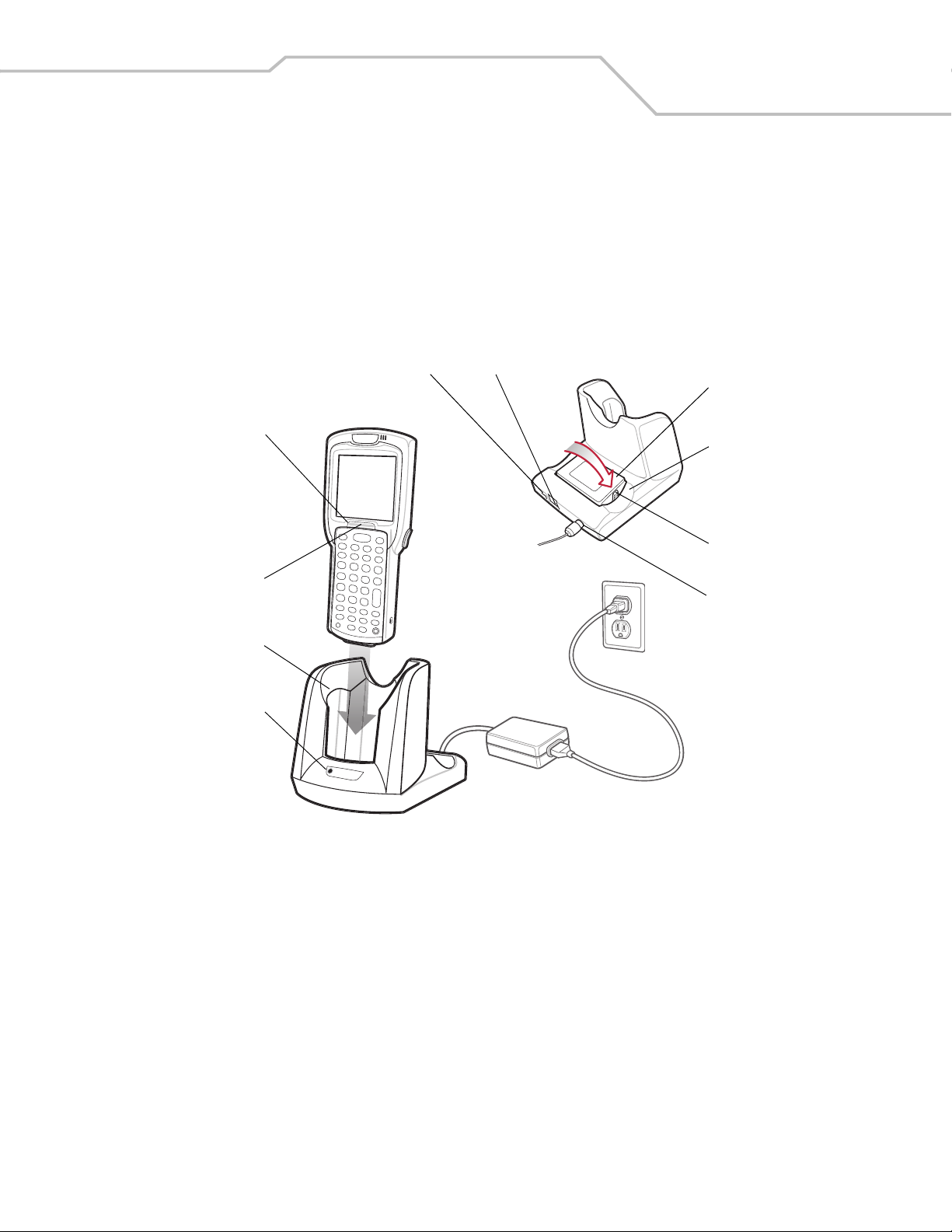
Accessories 2-5
Battery Charging
The Single Slot Serial/USB cradle can charge the mobile computer main battery and a spare battery simultaneously.
To charge the mobile computer:
1. Connect the Single Slot Serial/USB cradle to a Symbol approved power source.
2. Slide the mobile computer into the mobile computer slot. The amber Charge LED Indicator indicates the mobile computer
battery charging status. The Standard Battery charges in less than four hours and the Extended Life Battery charges in less
than six hours. See Table 2-1 for charging status indications.
Scan/Charge
Indicator
LED Bar
Charge LED
Indicator
(amber)
Mobile
Computer Slot
Spare
Battery
Charging
LED
USB Port
Serial Port
Spare
Battery
Spare
Battery
Charging
Slot
Battery
Clip
Power Port
Figure 2-2. Single Slot Serial/USB Cradle
3. When charging is complete, remove the mobile computer from the mobile computer slot.
To charge a spare battery:
1. Connect the Single Slot Serial/USB cradle to a Symbol approved power source.
2. Insert the spare battery into the spare battery charging slot, bottom first, and pivot the top of the battery down onto the
contact pins.
3. Gently press down on the battery to ensure proper contact.
4. The cradle Spare Battery Charging LED indicates the spare battery charging status. The Standard Battery usually charges in
less than four hours and the Extended Life Battery usually charges in less than six hours. See Table 2-1 for charging status
indications.
5. When charging is complete, press the battery clip and lift the battery out of the slot.
Page 46
MC3000 Integrator Guide2-6
LED Charge Indications
The Single Slot Serial/USB cradle uses the amber Charge LED Indicator to indicate MC3000 battery charging status and the Spare
Battery Charging LED to indicate spare battery charging status. See Table 2-1 for charging status indications.
Table 2-1. LED Charging Status Indicators
LED Indication
Mobile Computer Charging (LED on mobile computer)
Off Mobile computer not placed correctly in the cradle; cable not connected correctly; charger is not powered.
Fast Blinking Amber Error in charging; check placement of mobile computer.
Slow Blinking Amber Mobile computer is charging.
Solid Amber Charging complete.
Note: When the battery is initially inserted in the mobile computer, the amber LED flashes once if the battery
power is low or the battery is not fully inserted.
Spare Battery Charging (LED on cradle)
Off No spare battery in slot; spare battery not placed correctly; cradle is not powered.
Fast Blinking Amber Error in charging; check placement of spare battery.
Slow Blinking Amber Spare battery is charging.
Solid Amber Charging complete.
Communication Setup
To connect the Single Slot Serial/USB cradle to a serial or USB device:
1. Connect Single Slot Serial/USB cradle cable to the communications port.
2. Slide the mobile computer into the mobile computer slot. The amber Charge LED Indicator indicates the mobile computer
battery charging status and that the mobile computer is seated in the cradle. For more information on communications setup
procedures, see USB Connection Setup on page 2-32 and/or Serial Communication Setup on page 2-30.
Page 47

Four Slot Charge Only Cradle
The Four Slot Charge Only cradle:
• Provides 5.4VDC power for operating the mobile computer and charging the battery.
• Simultaneously charges up to four mobile computers.
Use only a Symbol approved power supply output rated 12 VDC and minimum 9 A. Use of an alternative power
supply will void the product warranty and may cause product damage. See the MC3000 User Guide for the
power supply regulatory compliance statement.
Setup
Connect the Four Slot Charge Only cradle to a Symbol approved power source.
Accessories 2-7
AC Line Cord
Power Port
Figure 2-3. Four Slot Charge Only Cradle, Setup
Power Supply
DC Cable
Page 48

MC3000 Integrator Guide2-8
Battery Charging
The Four Slot Charge Only cradle can charge up to four mobile computers simultaneously.
To charge the mobile computer:
1. Connect the Four Slot Charge Only cradle to a Symbol approved power source.
2. Slide the mobile computer into the mobile computer slot.
Charge LED
Indicator
(amber)
Scan/Charge
Indicator
LED Bar
Mobile
Computer
Slot
Power LED
Figure 2-4. Four Slot Charge Only Cradle
3. The mobile computer amber Charge LED Indicator indicates the mobile computer battery charging status. The Standard
Battery usually charges in less than four hours and the Extended Life Battery usually charges in less than six hours. See Table
2-1 on page 2-6 for charging status indications.
4. When charging is complete, remove the mobile computer from the cradle.
Power LED
The green Power LED lights to indicate that the Four Slot Charge Only cradle is connected to a power source.
LED Charge Indications
The Four Slot Charge Only cradle uses the amber Charge LED Indicator to indicate battery charging status. See Table 2-1 on
page 2-6 for charging status indications.
Page 49

Accessories 2-9
Four Slot Ethernet Cradle
This section describes how to set up and use a Four Slot Ethernet cradle with the mobile computer.
The Four Slot Ethernet cradle:
• Provides 5.4 VDC power for operating the mobile computer.
• Connects the mobile computer (up to four) to an Ethernet network.
You cannot ActiveSync using the Four Slot Ethernet cradle. To ActiveSync with a host computer, use the SIngle Slot Serial/USB cradle.
Use only a Symbol approved power supply output rated 12 VDC and minimum 9 A. Use of an alternative power
supply will void the product warranty and may cause product damage. See the MC3000 User Guide for the
power supply regulatory compliance statement.
Setup
Connect the Ethernet cradle (Ethernet port 1) to an Ethernet hub or a port on the host device. Connect the Ethernet cradle (power port)
to a Symbol approved power supply.
Ethernet Port 1
Ethernet Switch
Connection
Power Port
Figure 2-5. Four Slot Ethernet Cradle Connection
Ethernet Cradle Drivers
The Ethernet cradle drivers are pre-installed on the MC3000 and initiate automatically when the MC3000 is placed in a properly
connected Four Slot Ethernet cradle.
When the mobile computer is inserted into the Four Slot Ethernet cradle, the LAN icon indicates that the mobile computer is
connected to a network.
Page 50
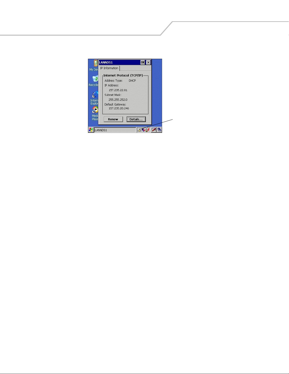
MC3000 Integrator Guide2-10
Double-tap the LAN icon to open the LANNDS1 window. This window display the TCP/IP information for the mobile computer.
LAN Icon
Figure 2-6. LANNDS1 Window
Page 51

Charging and Communication
Insert the mobile computer into a slot to begin charging and initiate communication.
Accessories 2-11
Charge LED
Indicator
(amber)
Scan/Charge
Indicator
LED Bar
Mobile
Computer
Slot
Speed LED
Link LED
Figure 2-7. Four Slot Ethernet Cradle
LED Charge Indications
The charge LED shows the status of the battery charging in the mobile computer. The Standard Battery usually charges in less than
four hours and the Extended Life Battery usually charges in less than six hours. See Table 2-1 on page 2-6 for charging status
indications.
Speed LED
The green Speed LED lights to indicate that the transfer rate is 100 Mbps. When it is not lit it indicates that the transfer rate is
10Mbps.
Link LED
The yellow Link LED blinks to indicate activity, or stays lit to indicate that a link is established. When it is not lit it indicates that there
is no link.
Page 52

MC3000 Integrator Guide2-12
Daisychaining Ethernet Cradles
To connect several cradles to an Ethernet network, up to four (recommended maximum) Ethernet cradles may be daisychained. The
Speed LED and the Link LED on the Ethernet port 2 function in the same way as the Speed LED and the Link LED on the front of the
cradle.
To daisychain cradles:
1. Connect the first Ethernet cradle to power and to the Ethernet Switch as shown on Figure 2-5 on page 2-9.
2. Connect power to the second Ethernet cradle.
3. Connect the daisychain Ethernet cable (either straight or twisted cable can be used) between Ethernet Port 2 of the first
cradle, and Ethernet Port 1 of the second cradle.
4. Connect additional cradles as described in Step 2 and Step 3. See Table 2-2 for bandwidth limations.
Speed LED
Ethernet Port 2
Link LED
Ethernet Port 1
Figure 2-8. Daisychaining Four Slot Ethernet Cradles
Bandwidth Considerations when Daisychaining
Each cradle added to the daisychain impacts the bandwidth allocated to each of the inserted mobile computers, particularly when the
mobile computers attempt to send and receive at data rates that exceed the bandwidth provided to the chain (typically 100 Mbps). If
a mobile computer in a daisychained cradle does not use its bandwidth, that bandwidth is available to other inserted mobile
computers.
Table 2-2 shows allocated bandwidth (based on 100 Mbps) for the number of daisychained cradles, with each mobile computer
attempting transmission at the maximum data rate.
Table 2-2. Daisychaining Bandwidth
Daisychained Ethernet
Cradles
Cradle 1 100,000,000 20,000,000*
Cradle 2 20,000,000 4,000,000
Cradle 3 4,000,000 800,000
Cradle 4 800,000 160,000
Cradle 5** 160,000 32,000
Cradle 6** 32,000 6,400
Cradle 7** 6,400 1,280
* The maximum bandwidth capacity for the mobile computer is 12,000,000 bits/sec.
** Depending on the application, allocated bandwidth may not be adequate.
Bandwidth Allocation For Each
Ethernet Cradle (bits/sec)
Bandwidth Allocation For Each
Mobile Computer (bits/sec)
Page 53

Wall Mount Bracket
Use the optional Wall Mount Bracket to mount a four slot cradle directly to a wall. To attach the Wall Mount Bracket:
1. Use the Wall Mount Bracket as a template and mark the locations of the four mounting screws.
Use fasteners appropriate for the type of wall and the Wall Mount Bracket, mounting slots. The Wall Mount
Bracket, mounting slots are designed for a fastener with a #8 pan head.
2. Mount the fasteners to the wall. The screw heads should protrude about a half of an inch from the wall.
3. Slip the Wall Mount Bracket over the screw heads and slide the Wall Mount Bracket down over the screw heads.
4. Tighten the screws to secure the Wall Mount Bracket to the wall.
Wall Mount Bracket
Accessories 2-13
Mounting Tabs (2)
Mounting Screws (4)
Mounting Slots
Figure 2-9. Wall Mount Bracket
To mount a four slot cradle:
5. Screw the supplied fasteners into the bottom of the four slot cradle. The screw heads should protrude about a quarter of an
inch from the cradle.
Four Slot Cradle Bottom
Mounting Screws (2)
Figure 2-10. Cradle Mounting Screws
Page 54

MC3000 Integrator Guide2-14
6. Align the Wall Mount Bracket mounting tabs with the mounting slots in the back of the four slot cradle. Slip the two
mounting tabs into mounting slots.
7. Swing the four slot cradle down onto the mounting bracket and align the mounting screws so that they fit into the screw
slots.
Wall Mount Bracket
Screw Slots
Power Supply Well
Figure 2-11. Wall Mount Bracket
8. Tighten the mounting screws to secure the four slot cradle to the Wall Mount Bracket.
Figure 2-12. Mounting Screws
9. Connect the power (see Figure 2-3 on page 2-7). The power supply should be located in the power supply well.
Page 55

Four Slot Spare Battery Charger
The Four Slot Spare Battery Charger simultaneously charges up to four spare batteries.
Use only a Symbol approved power supply output rated 12 VDC and minimum 3.3 A. Use of an alternative
power supply will void the product warranty and may cause product damage. See the MC3000 User Guide for
the power supply regulatory compliance statement.
Setup
Connect the Four Slot Spare Battery Charger to a Symbol approved power source.
Accessories 2-15
AC Cord
Power Port
DC Cable
Power
Supply
Figure 2-13. Four Slot Spare Battery Charger Setup
Page 56

MC3000 Integrator Guide2-16
Spare Battery Charging
To charge up to four MC3000 spare batteries:
1. Insert the spare battery into the spare battery charging slot, bottom first.
2. Pivot the top of the battery down onto the contact pins.
Power Supply
2
1
Spare
Battery
Charging
Slot
Spare Battery
Charging LEDs (4)
Battery
Clip
Spare
Batteries
Figure 2-14. Four Slot Spare Battery Charger
3. Gently press down on the battery to ensure proper contact. The Standard Battery usually charges in less than four hours and
the Extended Life Battery usually charges in less than six hours. See Table 2-1 on page 2-6 for charging status indications.
4. When charging is complete, press the battery clip and lift battery out of the slot.
LED Charge Indications
The Spare Battery Charging LEDs indicate the spare battery charging status. The Spare Battery Charging LEDs are arranged in the
same pattern as the spare battery charging slots so that the charging status of each battery can be identified. See Table 2-1 on page
2-6 for charging status indications.
Page 57

Accessories 2-17
Cables
This section describes how to setup and use the cables. The cables are available with a variety of connection capabilities.
The following MC3000 Communication/Charge cables are available:
• Serial (RS232) Charge cable (9-pin D female with power input receptacle)
• USB Client Charge cable (standard-A connector and a barrel receptacle for power).
Use only a Symbol approved power supply output rated 5.4 VDC and minimum 3 A. Use of an alternative power
supply will void the product warranty and may cause product damage. See the MC3000 User Guide for the
power supply regulatory compliance statement.
The following printer cables are available directly from the printer manufacturer:
• O’Neil printer cable
• Zebra printer cable.
• Monarch printer cable.
Figure 2-15. Cables (MC3000 Connector)
The MC3000 Communication/Charge cables:
• Provide the mobile computer with operating and charging power when used with the Symbol approved power supply.
• Synchronize information between the mobile computer and a host computer. With customized or third party software, it can
also synchronize the mobile computer with corporate databases.
• Provide serial connection through the serial pass-through port for communication with a serial device, such as a host
computer. For communication setup procedures, see Serial Communication Setup on page 2-30.
• Provide USB connection through the USB pass-through port for communication with a USB device, such as a host computer.
For communication setup procedures, see USB Connection Setup on page 2-32.
Dedicated printer cables, provide communication with a dedicated printer.
Page 58

MC3000 Integrator Guide2-18
Setup
The MC3000 Communication/Charge cables can connect with a serial/USB device, such as a printer or host computer, through its
serial or USB port.
Serial (RS232)
Cable
USB Host Cable
Mini-B Connector
MC3000 Connector
Power Input
Connector
Top View
Power Input
Barrel Connector
USB Client Cable
Standard-A
Connector
Figure 2-16. MC3000 Communication/Charge Cables
Battery Charging
The MC3000 Communication/Charge cables can charge the mobile computer battery and supply operating power.
To charge the mobile computer battery:
1. Connect the MC3000 Communication/Charge cable power input connector to the Symbol approved power source.
2. Attach the bottom of the mobile computer to the MC3000 connector and gently press in until the snaps latch on the mobile
computer.
3. The mobile computer amber Charge LED Indicator indicates the mobile computer battery charging status. The Standard
Battery usually charges in less than four hours and the Extended Life Battery usually charges in less than six hours. See Table
2-1 on page 2-6 for charging status indications.
4. When charging is complete, remove the cable by gently pulling the mobile computer and the cable apart until the snaps
release the mobile computer.
LED Charge Indications
The MC3000 Communication/Charge cables use the amber Charge LED Indicator to indicate the MC3000 battery charging status. See
Table 2-1 on page 2-6 for charging status indications.
Communication Setup
To connect the MC3000 Communication/Charge cables to a serial or USB device:
1. Connect serial/USB end of the MC3000 Communication/Charge cable into the communications port.
2. Connect the MC3000 connector end to the MC3000 Communication/Charge cable to the mobile computer. For more
information on communications setup procedures, see USB Connection Setup on page 2-32 and/or Serial Communication
Setup on page 2-30.
Page 59

Accessories 2-19
Universal Battery Charger (UBC) Adapter
The UBC Adapter can be used with a power supply as a standalone spare battery charger or it can be used with the four station
UBC2000 to simultaneously charge up to four spare batteries. For additional information on the UBC 2000, refer to the UBC 2000 Quick
Reference Guide, p/n 70-33188-xx.
Use only a Symbol approved power supply output rated 15 VDC and minimum 1.5 A. Use of an alternative
power supply will void the product warranty and may cause product damage. See the MC3000 User Guide for
the power supply regulatory compliance statement.
Setup
Connect the UBC Adapter to a Symbol approved power source.
Power Port
DC Cable
AC Line Cord
Figure 2-17. UBC Adapter Setup
Spare Battery Charging
To charge spare batteries:
1. Insert the spare battery into the spare battery charging slot, bottom first.
Power Supply
Page 60
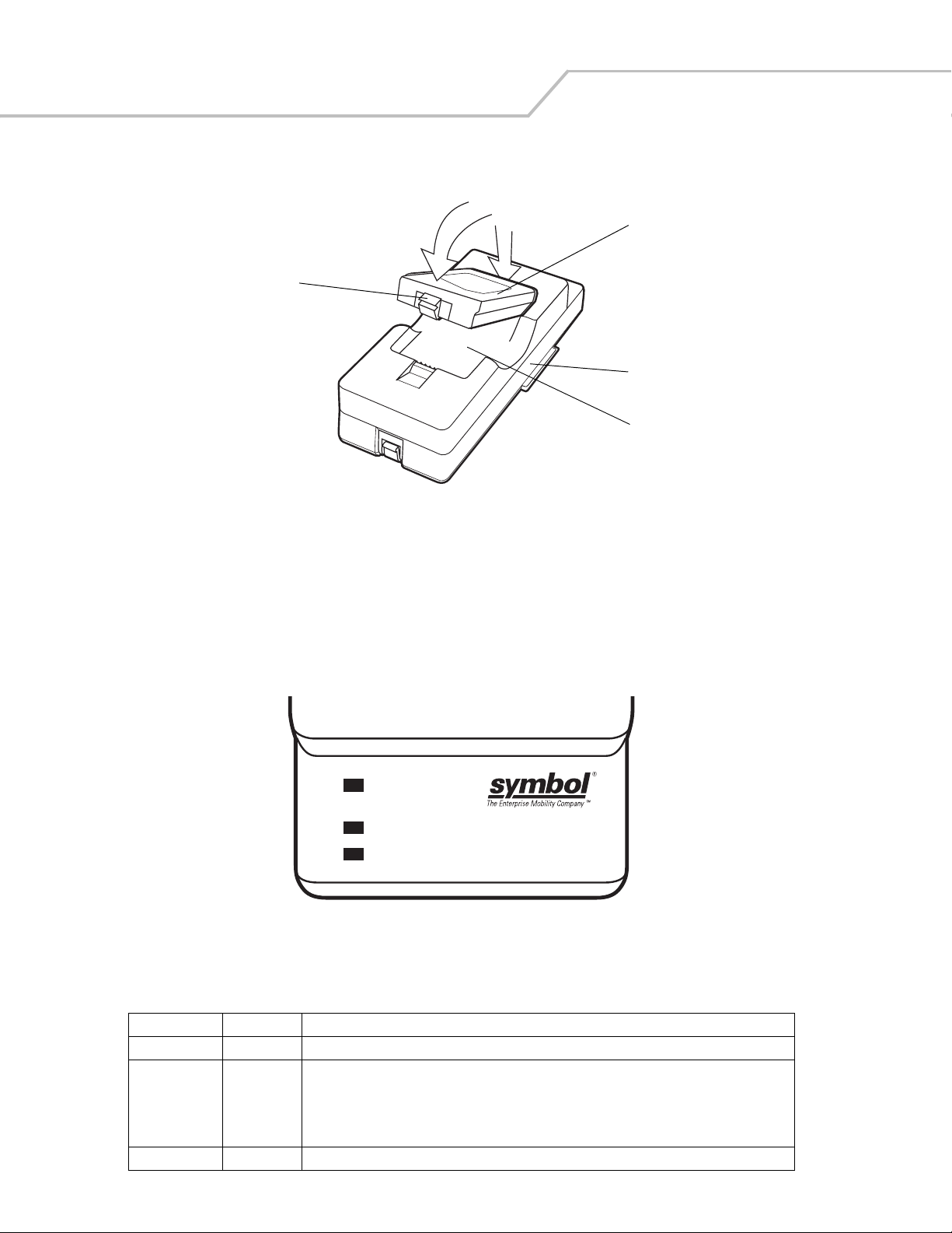
MC3000 Integrator Guide2-20
2. Pivot the top of the battery down onto the contact pins.
2
1
Battery Clip
Battery
UBC Adapter
Spare Battery
Charging Slot
Figure 2-18. UBC Adapter Battery Insertion
3. Gently press down on the battery to ensure proper contact. The Standard Battery usually charges in less than four hours and
the Extended Life Battery usually charges in less than six hours. See Table 2-3 for charging status indications.
4. When charging is complete, press the battery clip and lift the battery out of the slot.
UBC Adapter LED Charge Indications
The UBC Adapter charging LEDs indicate the battery charging status.
POWER
READY or STANDBY or FAULT
(Green) (Flashing Yellow) (Solid Y ellow)
CHARGING
(Solid Yellow)
Figure 2-19. UBC Adapter LEDs
Table 2-3. UBC Adapter Charge LED Status Indications
LED Indication Description
POWER Green Power is connected to the UBC Adapter.
READY or Green Charging complete.
STANDBY or Flashing-
Yel low
FAULT Yellow Charging error, check placement of mobile computer/spare battery.
CHARGING Yellow Normal charge.
The battery was deeply discharged and is being trickle charged to bring the voltage up to the
operating level. After operating level voltage is achieved, the battery charges normally.
Page 61
Accessories 2-21
Secure Device Card
The Secure Device (SD) card provides secondary non-volatile storage (the flash memory is slower than RAM). The SD card holder is
located under the battery.
Follow proper Electro-Static Discharge (ESD) precautions to avoid damaging the SD card. Proper ESD
precautions include, but are not limited to, working on an ESD mat and ensuring that the operator is properly
grounded.
Do not use the SD card slot for any other accessories.
Select SD cards with environmental and/or the write cycle performance specifications that meet or exceed
the application requirements.
To insert the SD card:
1. Remove the battery (see Main Battery Removal on page 1-16).
2. Lift the SD card retaining door.
3. Position the SD card, with the contacts down, into the SD card slot. The SD card corner notch fits into the slot only one way.
4. Snap the retaining door closed.
SD Card Retaining Door
Figure 2-20. Inserting the SD card
5. Replace the battery (see Install Main Battery on page 1-7).
SD Card
Page 62

MC3000 Integrator Guide2-22
Copy Files onto the SD Card
The SD card can be used to store files or programs used by the mobile computer. Files may be copied using an available file browser,
or using ActiveSync. InkWiz is a provided tool that is being used as an example of how to access data on the SD card.
1. From the Series 3000 Demo window, double-tap the Files icon. The InkWiz Example window appears.
Figure 2-21. InkWiz Window
2. To copy a file to the SD card, select a file and tap the file to highlight. The MSIMGSIZ.DAT file in the Tem p partition is being
used as an example.
3. Tap Edit - Copy to copy the file.
Figure 2-22. InkWiz, Copy File
4. Tap the Storage Card partition to highlight.
Page 63

5. Tap the Edit - Paste to paste the file into the Storage Card partition. The Storage Card partition now shows that the
MSIMGSIZ.DAT file is in the Storage Card partition.
Figure 2-23. InkWiz, Paste File
Delete a File From The SD Card
InkWiz is a provided tool that can be used to delete data from the SD card.
Accessories 2-23
1. Tap the MSIMGSIZ.DAT file to highlight.
2. Tap File - Del to delete the file from the Storage Card partition. The Question window appears.
3. Tap Yes to confirm the file deletion.
4. The Storage Card partition now shows that the MSIMGSIZ.DAT file is not in the Storage Card partition.
Figure 2-24. InkWiz, Delete File
Page 64

MC3000 Integrator Guide2-24
Format an SD Card
Use the Storage Manager to format the SD card.
1. Tap Start - Settings -Control Panel to access the Windows Control Panel.
Figure 2-25. Windows Control Panel
2. Double tap the Storage Manager icon to access the Storage Properties Window.
Do not select any other partitions for formatting. The DSK3: SD/MMC Card selection is the only entry that can
be formatted. Formatting the other partitions may render the mobile computer unusable.
Figure 2-26. Storage Properties SD Card Select Window
3. Tap the Store Info: drop down menu and select the DSK3: SD/MMC Card.
4. Tap Dismount to dismount the SD card.
Page 65

Accessories 2-25
5. If the SD card does not have an existing partition, tap New. The Create New Partition dialog box appears. If a partition
exists, proceed to step 7.
Figure 2-27. Create New Partition Window
6. In the Name: text box enter a partition name, and tap OK. The Storage Properties window appears.
Figure 2-28. Storage Properties Window
7. The Storage Properties window displays the new partition name in the Partitions: box. The asterisk next to the partition
name, indicates that the partition is mounted. The partition must be dismounted before it can be formatted.
8. Tap Dismount, the asterisk next to the partition name disappears indicating that the partition is dismounted.
Page 66

MC3000 Integrator Guide2-26
9. Tap Properties, the Partition Properties window appears.
Figure 2-29. Partition Properties
10. Tap Format, the Format window appears.
Figure 2-30. Format Windows
11. The default settings for the Format window are to perform a Quick Format. To perform a full format tap the Quick Format
check box to uncheck.
12. Tap Start, the Format confirmation window appears.
Figure 2-31. Format Confirmation Window
Page 67

Accessories 2-27
13. Tap Yes, the Format in progress window appears.
Figure 2-32. Format In Progress Window
14. The Format in progress window completion bar indicates the status of the format. When the format is complete the Format
complete window appears with a Format Complete message.
Figure 2-33. Format Complete Window
15. Tap OK, the Partition Properties window appears.
.
Figure 2-34. Partition Properties and Format Windows
Page 68
MC3000 Integrator Guide2-28
16. Tap OK, the Storage Properties window appears.
Figure 2-35. Storage Properties Window
17. Tap OK, to exit the Storage Manager.
Page 69

Accessories 2-29
Serial/USB Communication
This section provides information on installing the appropriate serial/USB communication software and setting up the appropriate
accessory to enable serial/USB communication between the mobile computer and the host device.
The mobile computer is capable of communicating with a number of hosts, including development computers, serial devices, printers,
etc. The communication accessories serve as data communication devices, enabling the information on the mobile computer to be
synchronized with the information on the host device using ActiveSync. With the appropriate accessory and software, the mobile
computer can establish a serial connection or a USB connection.
For a serial or USB connection, use one of the following:
• Single Slot Serial/USB cradle
• MC3000 Communication/Charge cables.
Installing Serial/USB Communication Software
To successfully communicate with various host devices communication software, such as Microsoft ActiveSync (version 3.7 or higher)
must be installed on the host computer. See Chapter 3, ActiveSync for ActiveSync installation procedures.
Communication Setup
The communication setup procedures for the Single Slot Serial/USB cradle and the MC3000 Communication/Charge cables are
provided in this section as an example. The serial communication setup procedures are provided in, Serial Communication Setup on
page 2-30 and the USB setup procedures are provided in, USB Connection Setup on page 2-32.
Page 70

MC3000 Integrator Guide2-30
Serial Communication Setup
The serial communication setup is used to set up to communicate between the host and the mobile computer using either a Single
Slot Serial/USB cradle or using one of the serial MC3000 Communication/Charge cables.
For serial communication using the Single Slot Serial/USB cradle, connect only the serial cable, do not connect both the
serial cable and the USB cable. If both serial and USB communication cables are required, the host computer USB port
must be disabled in ActiveSync before serial communication can be enabled.
Serial Connection Setup
1. On the mobile computer, Series 3000 Demo window double-tap the Ctl Panel icon and double-tap on Comm Settings. The
Comm Settings, window appears.
Figure 2-36. Comm Settings Window
2. The Comm port default value is set to USB. Highlight Port, and use the left and right arrow buttons to select the
value. Change the value to a serial setting appropriate for the host computer (typically Serial1 @ 115200).
3. Tap OK to exit the Comm Settings window.
4. Tap X to exit the Control Panel window.
5. Ensure that ActiveSync was installed on the host computer and a partnership was created. See Setting Up an ActiveSync
Connection on the Host Computer on page 3-4 for more information.
6. If ActiveSync is not running on the host computer, select Start - Programs - Microsoft ActiveSync to start ActiveSync, to
start.
Figure 2-37. ActiveSync - Not Connected
Page 71

7. In the ActiveSync window, select File - Connection Settings, the Connection Settings window appears.
8. Select the appropriate COM port for the host computer.
Accessories 2-31
Figure 2-38. Serial Connection Setting
9. Tap OK to save any changes made.
Every mobile computer should have a unique device name. Never try to synchronize more than one mobile
computer to the same name.
10. Connect the device to the host computer. See Figure 2-1 on page 2-4 to set up a Single Slot Serial/USB cradle, or see Figure
2-16 on page 2-18 for cable connections.
The cradle requires a dedicated port. It cannot share a port with an internal modem or other device. Refer to
the host computer documentation to locate the serial port(s).
11. Upon connection, synchronization occurs automatically.
Page 72

MC3000 Integrator Guide2-32
USB Connection Setup
The USB communication setup is used to set up to communicate between the host and the mobile computer using either a Single Slot
Serial/USB cradle or using one of the serial MC3000 Communication/Charge cables.
For serial communication using the Single Slot Serial/USB cradle, connect only the USB cable, do not connect both the
USB cable and the serial cable. If both serial and USB communication cables are required, the host computer USB port
is the default setting in ActiveSync.
1. On the mobile computer, Series 3000 Demo window double-tap the Ctl Panel icon and double-tap on Comm Settings. The
Comm Settings, window appears.
Figure 2-39. Comm Settings Window
2. Confirm that the Comm port default value is set to USB. If it is not set to USB then with Port highlighted, use the left
and right arrow buttons to set the value to USB.
3. Tap OK to exit the Comm Settings window.
4. Tap X to exit the Control Panel window.
5. Ensure that ActiveSync was installed on the host computer and a partnership was created. See Setting Up an ActiveSync
Connection on the Host Computer on page 3-4 for more information.
6. If ActiveSync is not running on the host computer, select Start - Programs - Microsoft ActiveSync to start ActiveSync, to start
7. Start ActiveSync, if it is not running on the host computer. To start, select Start - Programs - Microsoft ActiveSync.
Figure 2-40. ActiveSync - Not Connected
Page 73

8. In the ActiveSync window, select File - Connection Settings, the Connection Settings window appears.
9. Confirm that the Allow USB check box is selected.
Accessories 2-33
Figure 2-41. USB Connection Setting
10. Tap OK to save any changes made.
Every mobile computer should have a unique device name. Never try to synchronize more than one mobile
computer to the same name.
11. Connect the device to the host computer. See Figure 2-1 on page 2-4 to set up a Single Slot Serial/USB cradle, or see Figure
2-16 on page 2-18 for cable connections.
The cradle requires a dedicated port. It cannot share a USB port with any other device. Refer to the computer
user manual supplied to locate the USB(s).
12. Upon connection, synchronization occurs automatically.
Cradle/Cable Setup
To use ActiveSync with a cradle or a MC3000 Communication/Charge cable, see Serial Connection Setup on page 2-30 and USB
Connection Setup on page 2-32 for communication setup procedures.
Page 74

MC3000 Integrator Guide2-34
Page 75

ActiveSync
Chapter Contents
Introduction . . . . . . . . . . . . . . . . . . . . . . . . . . . . . . . . . . . . . . . . . . . . . . . . . . . . . . . . . . . . . . . . . . . . . . . . . . . . .3-3
Mobile Computer Setup . . . . . . . . . . . . . . . . . . . . . . . . . . . . . . . . . . . . . . . . . . . . . . . . . . . . . . . . . . . . . . . . . . . .3-3
Installing ActiveSync . . . . . . . . . . . . . . . . . . . . . . . . . . . . . . . . . . . . . . . . . . . . . . . . . . . . . . . . . . . . . . . . . . . . . .3-4
Setting Up an ActiveSync Connection on the Host Computer. . . . . . . . . . . . . . . . . . . . . . . . . . . . . . . . . . . . . . .3-4
Setting up a Partnership. . . . . . . . . . . . . . . . . . . . . . . . . . . . . . . . . . . . . . . . . . . . . . . . . . . . . . . . . . . . . . . .3-5
Page 76

MC3000 Integrator Guide3-2
Page 77

ActiveSync 3-3
Introduction
To communicate with various host devices, install Microsoft ActiveSync (version 3.7 or higher) on the host computer. Use ActiveSync
to synchronize information on the mobile computer with information on the host computer. Changes made on the mobile computer or
host computer appear in both places after synchronization.
ActiveSync software:
• Allows mobile computer-compatible host applications to be run on the mobile computer. ActiveSync replicates data from the
mobile computer so the host application can view, enter, and modify data on the mobile computer.
• Synchronizes files between the mobile computer and host computer, converting the files to the correct format.
• Backs up the data stored on the mobile computer. Synchronization is a one-step procedure that ensures the data is always
safe and up-to-date.
• Copies (rather than synchronizes) files between the mobile computer and host computer.
• Controls when synchronization occurs by selecting a synchronization mode, e.g., set to synchronize continually while the
mobile computer is connected to the host computer, or set to only synchronize on command.
• Selects the types of information to synchronize and control how much data is synchronized.
Mobile Computer Setup
The mobile computer can be set up to communicate either with a serial connection or a USB connection. Chapter 2, Accessories
provides the accessory setup and cable connection information for use with the mobile computer. The mobile computer
communication settings must be set to match the communication settings used with ActiveSync.
1. On the mobile computer double-tap the Ctl Panel icon and double-tap Comm Settings to display the Comm Settings, window.
Figure 3-1. Comm Settings Window
2. With Port highlighted, use the left and right arrow buttons to select the value. Select the Comm port setting
appropriate for the host computer, choose the default value of USB, or set to Serial1 @ 115200 (device dependant).
3. Tap OK to exit the Comm Settings window and tap X to exit the Control Panel window.
4. Proceed with installing ActiveSync on the host computer and setting up a partnership.
Installing ActiveSync
To install ActiveSync on the host computer, download the latest version of the software from the Microsoft web site at
http://www.microsoft.com. Refer to the installation and RAS instructions included with the ActiveSync software.
Page 78

MC3000 Integrator Guide3-4
Microsoft recommends installing ActiveSync on the host computer before connecting the mobile computer.
Before setting up a partnership between the mobile computer and host computer. See the Chapter 2, Accessories for a
list of the accessories that can be used.
Setting Up an ActiveSync Connection on the Host Computer
1. Select Start - Programs - Microsoft ActiveSync on the host computer. The Microsoft ActiveSync window appears.
Figure 3-2. Microsoft ActiveSync Window
Assign each mobile computer a unique device name. Do not try to synchronize more than one mobile
computer to the same name.
2. In the Microsoft ActiveSync window, select File - Connection Settings. The Connection Settings window appears.
Figure 3-3. Connection Settings Window
3. Select the appropriate check box for the type of connection used.
4. Select the Show status icon in Taskbar check box.
5. Select OK to save any changes made.
Page 79

ActiveSync 3-5
Setting up a Partnership
After ActiveSync installation is complete, the ActiveSync Setup Wizard sets up a partnership to synchronize information between the
mobile computer and host computer and customize synchronization settings.
To set up a partnership:
1. Connect the mobile computer to the host computer using an accessory described in Chapter 2, Accessories.
2. If the Get Connected window does not appear on the host computer, select Start - Programs - Microsoft ActiveSync - File -
Get Connected.
Figure 3-4. Get Connected Window
3. On the host computer, select Next in the Get Connected window.
4. The host computer and the mobile computer attempt to synchronize. The New Partnership window appears.
Figure 3-5. New Partnership Window
Page 80

MC3000 Integrator Guide3-6
5. Click the Standard partnership radio button and then select Next. The New Partnership/Specify how to synchronize data
window appears.
Figure 3-6. How To Sync Window
6. Click the Synchronize with this desktop computer radio button and select Next. The New Partnership/Select Number of
Partnerships window appears.
Figure 3-7. Select Number of Partnerships Window
Page 81

ActiveSync 3-7
7. Click the Yes, I want to synchronize with only this computer radio button and then select Next. The New Partnership/Select
Synchronization Settings window appears.
Figure 3-8. Select Synchronization Settings Window
8. To synchronize a particular type of information, select its check box. To stop synchronization of that information, clear its
check box.
9. Click Next. The New Partnership/Setup Complete window appears.
Figure 3-9. Setup Complete Window
Page 82

MC3000 Integrator Guide3-8
10. Select Finish. The Connected window appears confirming the connection between the mobile computer and the host.
Figure 3-10. ActiveSync Connected Window
During the first synchronization, information stored on the host computer is copied to the mobile computer. When the copy is complete
and all data is synchronized, the mobile computer can be disconnected from the host computer.
The first ActiveSync operation must be performed with a local, direct connection.
To retain partnerships after a cold boot, capture partnership registry information in a .reg file and save it in
the platform directory.
For more information about using ActiveSync, start ActiveSync on the host computer, then refer to the ActiveSync Help.
Page 83

Software Installation on Development PC
Contents
Introduction . . . . . . . . . . . . . . . . . . . . . . . . . . . . . . . . . . . . . . . . . . . . . . . . . . . . . . . . . . . . . . . . . . . . . . . . . . . . 4- 3
Required System Configurations . . . . . . . . . . . . . . . . . . . . . . . . . . . . . . . . . . . . . . . . . . . . . . . . . . . . . . . . . . . . .4-3
DCP . . . . . . . . . . . . . . . . . . . . . . . . . . . . . . . . . . . . . . . . . . . . . . . . . . . . . . . . . . . . . . . . . . . . . . . . . . . . . . . . . . . .4-3
Components . . . . . . . . . . . . . . . . . . . . . . . . . . . . . . . . . . . . . . . . . . . . . . . . . . . . . . . . . . . . . . . . . . . . . . . . .4-4
Platform SDK . . . . . . . . . . . . . . . . . . . . . . . . . . . . . . . . . . . . . . . . . . . . . . . . . . . . . . . . . . . . . . . . . . . . . . . . . . . .4-4
SMDK for C. . . . . . . . . . . . . . . . . . . . . . . . . . . . . . . . . . . . . . . . . . . . . . . . . . . . . . . . . . . . . . . . . . . . . . . . . . . . . .4-4
Components . . . . . . . . . . . . . . . . . . . . . . . . . . . . . . . . . . . . . . . . . . . . . . . . . . . . . . . . . . . . . . . . . . . . . . . . .4-6
Installing Other Development Software . . . . . . . . . . . . . . . . . . . . . . . . . . . . . . . . . . . . . . . . . . . . . . . . . . . . . . .4-6
Software Updates . . . . . . . . . . . . . . . . . . . . . . . . . . . . . . . . . . . . . . . . . . . . . . . . . . . . . . . . . . . . . . . . . . . . . . . .4-6
Page 84

MC3000 Integrator Guide4-2
Page 85

Software Installation on Development PC 4-3
Introduction
To develop applications to run on the mobile computer, use one or both of the following:
• Symbol Mobility Developer Kit (SMDK) for C
• Platform Software Developer Kit (Platform SDK) for MC3000
• Device Configuration Package (DCP) for MC3000.
The SMDK for C is a development tool used to create native C and C++ applications for all Symbol mobile computers. It includes
documentation, header files (.H), and library files (.LIB) for native code application development that targets Symbol value-add APIs.
The Windows CE Platform SDK for MC3000c42 is used in conjunction with the SMDK for C to create Windows CE applications for
the MC3000 mobile computer. The Platform SDK installs a new Windows CE device type and its associated libraries onto the
development PC. This new device is added to the Active WCE Configuration field of Microsoft eMbedded Visual C++ 4.0 (eVC4).
The DCP is required to create and download hex images that represent flash partitions to the mobile computer. The DCP includes
documentation, flash partitions, Terminal Configuration Manager (TCM) and the associated TCM scripts.
Required System Configurations
The minimum host system configuration required to use the SMDK for C and DCP for MC3000 is:
• IBM-compatible host computer with Pentium 450 MHz processor or higher
• Microsoft Windows XP or Microsoft Windows 2000 operating system
• 128 MB RAM
• 100 MB available hard disk space
•CD-ROM drive
• One available serial port
•Mouse
• Adobe
• Microsoft ActiveSync version 3.7 or higher, available at the Microsoft web site: http://www.microsoft.com
• Microsoft Embedded Visual C++ v4.0 with SP2, available at the Microsoft web site: http://www.microsoft.com
®
Acrobat® Reader® 3.0 or higher, available at the Microsoft web site: http://www.microsoft.com
DCP
To download and install the DCP:
1. Download the DCP from the Symbol web site: http://devzone.symbol.com.
2. Select Developer Downloads and sign in.
3. Select PocketPC/WinCE/CE.Net Platform.
4. On the drop-down menu below the MC3000 product, select Device Configuration Package (DCP) for MC3000.
5. Save the .exe file to the development computer.
6. Locate the .exe file on the development computer, double-click the file and follow the install screen prompts.
7. Once installed, access the components of the DCP from the Symbol Device Configuration Package (DCP) for MC3000 program
group of the Windows Start Menu.
Page 86

MC3000 Integrator Guide4-4
Components
Table 4-1 lists the MC3000 DCP components and their locations.
Table 4-1. DCP for MC3000 Components and Locations
Component Description Directory Location
Files that make up the
flash partitions
Hex image - default
location
Used to configure the mobile computer. \Program Files\Symbol Device Configuration Packages\MC3000\v1.0\Flash
Folders
Loads onto the mobile computer for configuration. \Program Files\Symbol Device Configuration Packages\MC3000\v1.0\Hex Images
Documentation Documents that provide guidance on using and
integrating the MC3000.
Readme Contains important information for the DCP. \Program Files\Symbol Device Configuration Packages\MC3000\v1.0
Scripts Used to customize flash partitions. \Program Files\Symbol Device Configuration Packages\MC3000\v1.0\TCM Scripts
TCM An application used to customize flash file system
partitions for the mobile computer.
Tools (Keyboard remap,
if any)
Start Menu:
Readme
Documentation
TCM
WEB Updates
Used in developing applications for the mobile
computer.
Specifies items to appear in the Start menu. \Documents and Settings\All Users\Start Menu\Programs
\Program Files\Symbol Device Configuration Packages\MC3000\v1.0
\Program Files\Symbol\TCM2
\Program Files\Symbol Device Configurations package\MC3000\v1.0\Tools\kbtool
Platform SDK
Different Platform SDKs are required for the Microsoft® Windows CE .NET 5.0 Professional and Microsoft® Windows CE .NET 5.0
Core platforms.
To download and install the appropriate Platform SDK:
1. Download the appropriate Platform SDK from the Symbol web site, http://devzone.symbol.com.
2. Select Developer Downloads and sign in.
3. Select PocketPC/WinCE/CE.Net Platform.
4. Select PSDK3000c50bXXXXX.exe for the Microsoft
PSDK3000c50aXXXXX.exe for the Microsoft
5. Save the .exe file to the development computer.
6. Run the file and follow the screen prompts to install.
®
®
Windows CE .NET 5.0 Professional platform or select
Windows CE .NET 5.0 Core platforms.
SMDK for C
To download and install the SMDK for C:
1. Download the SMDK from the Symbol web site, http://devzone.symbol.com.
2. Select Developer Downloads and sign in.
3. Select PocketPC/WinCE/CE.Net Platform.
4. Select Symbol Mobility Developer Kit for C.
5. Select the latest version, and save the .exe file to the development computer.
Page 87

Software Installation on Development PC 4-5
6. Locate the .exe file on the development computer, double-click the executable file and follow the install screen prompts.
7. Once installed, access the components of the SMDK for C from the Symbol Mobility Developer Kit for C program group of
the Windows Start menu.
8. The sample applications provide examples of how to interface with the Symbol API functions. To build a sample application,
open the Samples folder from the Windows Start menu. Open the folder for the desired sample and then open the project
file. The project file has an extension of VCP. Microsoft Visual C++ v4.0 automatically launches. Select WinCE as the Active
WCE Configuration. Select Win32 (WCE ARMV4) Debug as the active configuration.
If both Microsoft Visual C++ v3.0 and Microsoft Visual C++ v4.0 are installed on the development computer,
ensure Microsoft Visual C++ v4.0 launches.
Page 88

MC3000 Integrator Guide4-6
Components
The sample applications provide examples of how to interface with the Symbol API functions. To build a sample application, open the
Samples folder from the Windows Start menu. Open the folder for the desired sample and then open the project file. The project file
has an extension of VCP. Microsoft Visual C++ v4.0 automatically launches. Select WinCE as the Active WCE Configuration. Select
Win32 (WCE ARMV4) Debug as the active configuration.
If both Microsoft Visual C++ v3.0 and Microsoft Visual C++ v4.0 are installed on the development computer,
ensure Microsoft Visual C++ v4.0 launches.
Table 4-2 lists the SMDK for C components.
Table 4-2. SMDK for C Components and Locations
Components Directory Location
SMDK (API) Help file and Readme file \Program Files\Symbol Mobility Developer Kit vx.x for C\
Sample applications for quick-start development \Program Files\Symbol Mobility Developer Kit vx.x for C\Samples\evc\
Header files with API prototypes and structures* \Program Files\Windows CE Tools\wce420\WinCE\Include\armv4
Import Library files* \Program Files\Windows CE Tools\wce420\WinCE\Lib\armv4
Start Menu
Readme
Help
Platform Integrator
Samples
Web Updates
\Documents and Settings\All Users\Start Menu\Programs
* The header files and library files are time and date stamped so they can be easily identified in the armv4 directories. The “date” is the date
on which the software release was assembled and the time is the version of the release. For example, a time of 1:00 signifies version 1.0.
Installing Other Development Software
Developing applications for the mobile computer may require installing other development software, such as application development
environments, on the development PC. Follow the installation instructions provided with the software.
Software Updates
Download updates to the SMDK for C from the Symbol Developer Zone web site at: http://devzone.symbol.com. Check this site
periodically for important updates and new software versions.
Page 89

Software Installation on Mobile Computer
Introduction . . . . . . . . . . . . . . . . . . . . . . . . . . . . . . . . . . . . . . . . . . . . . . . . . . . . . . . . . . . . . . . . . . . . . . . . . . . . 5-3
ActiveSync . . . . . . . . . . . . . . . . . . . . . . . . . . . . . . . . . . . . . . . . . . . . . . . . . . . . . . . . . . . . . . . . . . . . . . . . . . . . . .5-3
Copying Files . . . . . . . . . . . . . . . . . . . . . . . . . . . . . . . . . . . . . . . . . . . . . . . . . . . . . . . . . . . . . . . . . . . . . . . .5-3
Adding Programs . . . . . . . . . . . . . . . . . . . . . . . . . . . . . . . . . . . . . . . . . . . . . . . . . . . . . . . . . . . . . . . . . . . . .5-5
Adding a Program from the Internet . . . . . . . . . . . . . . . . . . . . . . . . . . . . . . . . . . . . . . . . . . . . . . . . . . . . . .5-5
IPL . . . . . . . . . . . . . . . . . . . . . . . . . . . . . . . . . . . . . . . . . . . . . . . . . . . . . . . . . . . . . . . . . . . . . . . . . . . . . . . . . . . . .5-5
AirBEAM. . . . . . . . . . . . . . . . . . . . . . . . . . . . . . . . . . . . . . . . . . . . . . . . . . . . . . . . . . . . . . . . . . . . . . . . . . . . . . . .5-5
SD Card. . . . . . . . . . . . . . . . . . . . . . . . . . . . . . . . . . . . . . . . . . . . . . . . . . . . . . . . . . . . . . . . . . . . . . . . . . . . . . . . .5-5
Page 90

MC3000 Integrator Guide5-2
Page 91

Software Installation on Mobile Computer 5-3
Introduction
With the appropriate accessory, software, and connection, the mobile computer can share information with the host computer. This
chapter provides information about installing software and files on the mobile computer.
Download/software installations can be performed using:
•ActiveSync
• Initial Program Loader (IPL)
•AirBEAM
•SD card.
ActiveSync
Use ActiveSync to copy files and/or programs from a host computer to the mobile computer.
Copying Files
1. Ensure that ActiveSync is installed on the host computer and that a partnership was created. For more information see,
Chapter 3, ActiveSync.
2. Connect the mobile computer to the host computer using a Single Slot Serial/USB cradle or an appropriate cable. See,
Chapter 2, Accessories for connection information.
3. On the host computer, select Start - Programs - ActiveSync.
Figure 5-1. ActiveSync Connected Window
Page 92
MC3000 Integrator Guide5-4
4. Select Explore.
Figure 5-2. ActiveSync Explorer
5. Double-click the folder to expand the folder contents.
Figure 5-3. Application Folder Contents
6. Use Explorer to locate the host computer directory that contains the file to download. Tap that directory in the left pane to
display its contents in the right pane.
7. Drag the desired file(s) from the host computer to the desired mobile device folder.
• Program Files folder: files stored in this folder are discarded after a cold boot.
• Application folder: files stored in this folder are retained after a cold boot.
Adding Programs
Install the appropriate software on the host computer before installing it on the mobile computer:
Page 93

Software Installation on Mobile Computer 5-5
1. Download the program to the host computer (or insert the CD or disk that contains the program into the host computer). The
program may consist of a single *.xip file, *.exe file, a *.zip file, or a Setup.exe file.
2. Read any installation instructions, ReadMe files, or documentation that comes with the program. Many programs provide
special installation instructions.
3. Connect the mobile computer to the host computer using an accessory described in Chapter 2, Accessories.
4. Ensure that a connection is established.
5. Double-click the executable file on the host computer.
If the file is an installer, the installation wizard begins. Follow the directions on the window. Once the software is installed
on the host computer, the installer transfers the software to the mobile computer.
If the file is not an installer, an error message states that the program is valid but is designed for a different type of computer.
Copy this file to the mobile computer (see Copying Files on page 5-3). Follow the installation instructions for the program in
the ReadMe file or documentation, or use ActiveSync Explore to copy the program file to the Program Files folder on the
mobile computer as described in ActiveSync on page 5-3. For more information on copying files using ActiveSync, refer to
ActiveSync Help.
6. When installation is complete, tap Start - Programs on the mobile computer, then tap the program icon.
Adding a Program from the Internet
1. Download the program to the mobile computer from the Internet using Internet Explorer.
2. Read any installation instructions, Read Me files, or documentation that comes with the program. Many programs provide
special installation instructions.
3. Tap the file, such as a .xip or .exe file, to launch the installation wizard. Follow the directions on the window.
IPL
Use IPL to download files onto the mobile computer. See Chapter 6, Creating/Loading Hex Images to download customized flash file
system partitions to the mobile computer and load hex files to the flash memory of the mobile computer.
AirBEAM
Use AirBEAM to download files onto the mobile computer and/or to transfer special software packages from a host server to the
mobile computer. For more information see, Chapter 8, AirBEAM Smart.
SD Card
Use the SD card to download/upload files to and from the mobile computer. See Secure Device Card on page 2-21 for more
information.
Page 94

MC3000 Integrator Guide5-6
Page 95

Creating/Loading Hex Images
Introduction . . . . . . . . . . . . . . . . . . . . . . . . . . . . . . . . . . . . . . . . . . . . . . . . . . . . . . . . . . . . . . . . . . . . . . . . . . . . .6-3
Starting Terminal Configuration Manager. . . . . . . . . . . . . . . . . . . . . . . . . . . . . . . . . . . . . . . . . . . . . . . . . . . . . .6-4
Defining Script Properties . . . . . . . . . . . . . . . . . . . . . . . . . . . . . . . . . . . . . . . . . . . . . . . . . . . . . . . . . . . . . . . . . .6-6
Creating the Script for the Hex Image . . . . . . . . . . . . . . . . . . . . . . . . . . . . . . . . . . . . . . . . . . . . . . . . . . . . . . . . .6-7
Opening a New or Existing Script . . . . . . . . . . . . . . . . . . . . . . . . . . . . . . . . . . . . . . . . . . . . . . . . . . . . . . . .6-7
Updating TCM 1.X Scripts . . . . . . . . . . . . . . . . . . . . . . . . . . . . . . . . . . . . . . . . . . . . . . . . . . . . . . . . . . . . . . 6-7
Copying Components to the Script . . . . . . . . . . . . . . . . . . . . . . . . . . . . . . . . . . . . . . . . . . . . . . . . . . . . . . .6-7
Saving the Script . . . . . . . . . . . . . . . . . . . . . . . . . . . . . . . . . . . . . . . . . . . . . . . . . . . . . . . . . . . . . . . . . . . . .6-7
Building the Image . . . . . . . . . . . . . . . . . . . . . . . . . . . . . . . . . . . . . . . . . . . . . . . . . . . . . . . . . . . . . . . . . . . . . . . .6-8
Sending the Hex Image . . . . . . . . . . . . . . . . . . . . . . . . . . . . . . . . . . . . . . . . . . . . . . . . . . . . . . . . . . . . . . . . . . . .6-9
TCM Error Messages . . . . . . . . . . . . . . . . . . . . . . . . . . . . . . . . . . . . . . . . . . . . . . . . . . . . . . . . . . . . . . . . . . . . .6-14
IPL Error Detection . . . . . . . . . . . . . . . . . . . . . . . . . . . . . . . . . . . . . . . . . . . . . . . . . . . . . . . . . . . . . . . . . . . . . . .6-15
Creating a Splash Screen. . . . . . . . . . . . . . . . . . . . . . . . . . . . . . . . . . . . . . . . . . . . . . . . . . . . . . . . . . . . . . . . . .6-17
Splash Screen Format . . . . . . . . . . . . . . . . . . . . . . . . . . . . . . . . . . . . . . . . . . . . . . . . . . . . . . . . . . . . . . . .6-17
Flash Storage . . . . . . . . . . . . . . . . . . . . . . . . . . . . . . . . . . . . . . . . . . . . . . . . . . . . . . . . . . . . . . . . . . . . . . . . . . .6-18
FFS Partitions . . . . . . . . . . . . . . . . . . . . . . . . . . . . . . . . . . . . . . . . . . . . . . . . . . . . . . . . . . . . . . . . . . . . . . .6-18
Working with FFS Partitions . . . . . . . . . . . . . . . . . . . . . . . . . . . . . . . . . . . . . . . . . . . . . . . . . . . . . . . . . . .6-18
RegMerge.dll . . . . . . . . . . . . . . . . . . . . . . . . . . . . . . . . . . . . . . . . . . . . . . . . . . . . . . . . . . . . . . . . . . .6-18
CopyFiles . . . . . . . . . . . . . . . . . . . . . . . . . . . . . . . . . . . . . . . . . . . . . . . . . . . . . . . . . . . . . . . . . . . . . .6-19
Non-FFS Partitions . . . . . . . . . . . . . . . . . . . . . . . . . . . . . . . . . . . . . . . . . . . . . . . . . . . . . . . . . . . . . . . . . . .6-19
Downloading Partitions to the Mobile Computer . . . . . . . . . . . . . . . . . . . . . . . . . . . . . . . . . . . . . . . . . . .6-19
IPL . . . . . . . . . . . . . . . . . . . . . . . . . . . . . . . . . . . . . . . . . . . . . . . . . . . . . . . . . . . . . . . . . . . . . . . . . . . . . . . . . . . .6-20
Partition Update vs. File Update . . . . . . . . . . . . . . . . . . . . . . . . . . . . . . . . . . . . . . . . . . . . . . . . . . . . . . . .6-20
Upgrade Requirements . . . . . . . . . . . . . . . . . . . . . . . . . . . . . . . . . . . . . . . . . . . . . . . . . . . . . . . . . . . . . . .6-20
Page 96

MC3000 Integrator Guide6-2
Page 97

Creating/Loading Hex Images 6-3
Introduction
Terminal Configuration Manager (TCM) is an application used to customize flash file system partitions for the mobile computer. The
most common use is to create an application partition hex file that contains the customer's application. TCM can also be used to load
hex files to the flash memory of the mobile computer.
The program resident on the mobile computer that receives the hex file and burns it to the flash memory is called Initial Program
Loader (IPL).
The customization of partitions is controlled by TCM scripts. The scripts contain all of the necessary information for building an image.
The script is a list of copy commands specifying the files to copy from the development computer to the partition.
TCM works with a pair of directory windows, one displaying the script and the other displaying the source files resident on the
development computer. Using standard windows drag and drop operations, files can be added and deleted from the script window.
The DCP includes scripts used by Symbol Technologies to build the standard factory installed Platform and Application partitions
provided on the mobile computer. The standard Platform partition contains drivers while the Application partition contains demo
applications and optional components. The standard TCM scripts can be found in the following folder: C:\Program Files\Symbol
Windows CE SMDK (MC3000)\SymbolPlatforms \MC3000\TCMScripts.
Before creating a script to build a hex image, identify the files required (system files, drivers, applications,
etc.) and locate the files’ source directories to make the script building process easier.
The required processes for building a hex image in TCM include:
• Starting TCM
• Defining script properties
• Creating the script for the hex image
• Building the image
• Sending the hex image to the mobile computer.
Screens displayed in this section are sample screens. The actual mobile computer screens may vary slightly.
Page 98

MC3000 Integrator Guide6-4
Starting Terminal Configuration Manager
Click the Start - Programs - Symbol - Symbol Device Configuration Packages - MC3000 C42V1.0 to start TCM.
The TCM window appears displaying two child windows: Script1 and File Explorer. The Script1 window contains a newly created
script and the File Explorer window contains a file explorer view used for selecting files to be placed in the script.
Table 6-1 lists the TCM window components.
Icon Component Function
Script Window Displays the files to be used in the creation of the partition(s).
File Explorer Window Used to select the files to be added to the script.
Create button Create a new script file.
Open button Open an existing script file.
Save button Save the current script file.
Figure 6-1. TCM Script 1 Window
Table 6-1. TCM Components
Large icons button View the current script items as large icons.
Page 99

Table 6-1. TCM Components (Continued)
Icon Component Function
Small icons button View the current script items as small icons.
List button View the current script items as a list.
Details button View the current script items with more details.
About button Display version information for TCM.
Properties button View/change the current script properties.
Creating/Loading Hex Images 6-5
Build button Build the current script into a set of hex files.
Check button Check the script for errors (files not found).
Send button Download the hex image to the mobile computer.
Tile button Arrange the sub-windows in a tiled orientation.
Build and Send button Build the current script into a set of hex images and send the hex
images to the mobile computer.
Preferences button View/change the global TCM options.
Page 100

MC3000 Integrator Guide6-6
Defining Script Properties
Before a script is created, the script properties must be defined. This defines the type of mobile computer, flash type, number of disks
being created and the memory configuration of each disk partition.
To define the script properties:
1. Select the Script window to make it active.
2. Click the Properties button. The Script Properties window - Partition Data tab appears.
Figure 6-2. Script Properties Window - Partition Data Tab
3. In the Te rm in al drop-down list, the MC3000C42a v1.0 or MC3000C42b v1.0 entry is already selected.
4. Use the default Flash Type.
5. In the Disks drop-down list, select the number of disk partitions to create.
6. Select the (memory) Size for each disk partition. Note that adding space to one disk partition subtracts space from another.
7. In the Access drop-down list for each disk partition, determine and select the Read/Write access option.
8. Click the Options tab. The Script Properties window - Options tab appears.
Figure 6-3. Script Properties Window - Options Tab
9. Set the paths for the Script File, Flash File and Hex File Build.
10. Click OK.
 Loading...