

Page 1
Hotshot
LS 2100/LS 2108
Product Reference Guide
Page 2

Page 3

Hotshot
LS 2100/LS 2108
Product Reference Guide
72-53399-01
Revision A
June 2002
Page 4

© 2002 by Symbol Technologies, Inc. All rights reserved.
No part of this publication may be reproduced or used in any form, or by any electrical or
mechanical means, without permission in writing from Symbol. This includes electronic or
mechanical means, such as photocopying, recording, or information storage and retrieval
systems. The material in this guide is subject to change without notice.
The software is provided strictly on an “as is” basis. All software, including firmware,
furnished to the user is on a licensed basis. Symbol grants to the user a non-transferable
and non-exclusive license to use each software or firmware program delivered hereunder
(licensed program). Except as noted below, such license may not be assigned,
sublicensed, or otherwise transferred by the user without prior written consent of Symbol.
No right to copy a licensed program in whole or in part is granted, except as pe rmitted under
copyright law. The user shall not modify, merge, or incorporate any form or portion of a
licensed program with other program material, create a derivative work from a licensed
program, or use a licensed program in a network without written permission fr om Symbol.
The user agrees to maintain Symbol’ s copyright notice on the lice nsed programs delivered
hereunder , and to include the same on any authori zed copi es it ma kes, in whole or i n pa rt.
The user agrees not to decompile, disassemble , decode, or reverse engineer any licensed
program delivered to the user or any portion thereof.
Symbol reserves the right to make changes to any software or product to improve reliability ,
function, or design.
Symbol does not assume any product liability arising out of, or in connection with, the
application or use of any product, circuit, or application described herein.
No license is granted, either expressly or by implication, estoppel, or otherwise under any
Symbol Technologies, Inc., intellectual property rights. An implied license only exists for
equipment, circuits, and subsystems contained in Symbol products.
Symbol, Spectrum One, and Spectrum24 are registered trademarks of Symbol
Technologies, Inc. Other product names mentioned in this guide may be trademarks or
registered trademarks of their respective companies and are hereby acknowledged.
Symbol Technologies, Inc.
One Symbol Plaza
Holtsville, New York 11742-1300
http://www.symbol.com
Page 5

Contents
Contents
About This Guide
Introduction . . . . . . . . . . . . . . . . . . . . . . . . . . . . . . . . . . . . . . . . . . . . . . . . . . . . . . . . . . . . . . . . . . . .xi
Chapter Descriptions. . . . . . . . . . . . . . . . . . . . . . . . . . . . . . . . . . . . . . . . . . . . . . . . . . . . . . . . . . . . .xi
Notational Conventions . . . . . . . . . . . . . . . . . . . . . . . . . . . . . . . . . . . . . . . . . . . . . . . . . . . . . . . . . . xiii
Related Publications . . . . . . . . . . . . . . . . . . . . . . . . . . . . . . . . . . . . . . . . . . . . . . . . . . . . . . . . . . . . xiii
Service Information . . . . . . . . . . . . . . . . . . . . . . . . . . . . . . . . . . . . . . . . . . . . . . . . . . . . . . . . . . . . . xiii
Symbol Support Center . . . . . . . . . . . . . . . . . . . . . . . . . . . . . . . . . . . . . . . . . . . . . . . . . . . . . . . . . . xiv
LS2108 Series Warranty . . . . . . . . . . . . . . . . . . . . . . . . . . . . . . . . . . . . . . . . . . . . . . . . . . . . . . . . xvii
LS2108 Series Warranty Coverage and Procedure . . . . . . . . . . . . . . . . . . . . . . . . . . . . . . . . xvii
General. . . . . . . . . . . . . . . . . . . . . . . . . . . . . . . . . . . . . . . . . . . . . . . . . . . . . . . . . . . . . . . . . . xviii
Chapter 1. Getting Started
Introduction . . . . . . . . . . . . . . . . . . . . . . . . . . . . . . . . . . . . . . . . . . . . . . . . . . . . . . . . . . . . . . . . . . 1-1
Unpacking Your Scanner. . . . . . . . . . . . . . . . . . . . . . . . . . . . . . . . . . . . . . . . . . . . . . . . . . . . . . . . 1-2
Setting Up the Scanner . . . . . . . . . . . . . . . . . . . . . . . . . . . . . . . . . . . . . . . . . . . . . . . . . . . . . . . . . 1-3
Installing the Interface Cable . . . . . . . . . . . . . . . . . . . . . . . . . . . . . . . . . . . . . . . . . . . . . . . . . 1-3
Connecting Power (if required). . . . . . . . . . . . . . . . . . . . . . . . . . . . . . . . . . . . . . . . . . . . . . . . 1-4
Configuring Your Scanner . . . . . . . . . . . . . . . . . . . . . . . . . . . . . . . . . . . . . . . . . . . . . . . . . . . 1-4
Connecting a Synapse Cable Interface . . . . . . . . . . . . . . . . . . . . . . . . . . . . . . . . . . . . . . . . . 1-5
Removing the Interface Cable . . . . . . . . . . . . . . . . . . . . . . . . . . . . . . . . . . . . . . . . . . . . . . . . 1-5
Chapter 2. Scanning
Introduction . . . . . . . . . . . . . . . . . . . . . . . . . . . . . . . . . . . . . . . . . . . . . . . . . . . . . . . . . . . . . . . . . . 2-1
Beeper Definitions . . . . . . . . . . . . . . . . . . . . . . . . . . . . . . . . . . . . . . . . . . . . . . . . . . . . . . . . . . . . . 2-2
LED Definitions . . . . . . . . . . . . . . . . . . . . . . . . . . . . . . . . . . . . . . . . . . . . . . . . . . . . . . . . . . . . . . . 2-4
Scanning in Hand-Held Mode . . . . . . . . . . . . . . . . . . . . . . . . . . . . . . . . . . . . . . . . . . . . . . . . . . . . 2-5
Aiming . . . . . . . . . . . . . . . . . . . . . . . . . . . . . . . . . . . . . . . . . . . . . . . . . . . . . . . . . . . . . . . . . . . . . . 2-6
Scanning in Hands-Free Mode . . . . . . . . . . . . . . . . . . . . . . . . . . . . . . . . . . . . . . . . . . . . . . . . . . . 2-7
Scanning in the Hands-Free Mode(LS2108) . . . . . . . . . . . . . . . . . . . . . . . . . . . . . . . . . . . . . 2-7
Chapter 3. Maintenance and Technical Specifications
Introduction . . . . . . . . . . . . . . . . . . . . . . . . . . . . . . . . . . . . . . . . . . . . . . . . . . . . . . . . . . . . . . . . . . 3-1
Maintenance . . . . . . . . . . . . . . . . . . . . . . . . . . . . . . . . . . . . . . . . . . . . . . . . . . . . . . . . . . . . . . . . . 3-1
Troubleshooting. . . . . . . . . . . . . . . . . . . . . . . . . . . . . . . . . . . . . . . . . . . . . . . . . . . . . . . . . . . . . . . 3-2
iii
Page 6

LS2100/LS2108 Product Reference Guide
Technical Specifications . . . . . . . . . . . . . . . . . . . . . . . . . . . . . . . . . . . . . . . . . . . . . . . . . . . . . . . . .3-4
Scanner Signal Descriptions. . . . . . . . . . . . . . . . . . . . . . . . . . . . . . . . . . . . . . . . . . . . . . . . . . . . . . 3-6
Chapter 4. User Preferences
Introduction. . . . . . . . . . . . . . . . . . . . . . . . . . . . . . . . . . . . . . . . . . . . . . . . . . . . . . . . . . . . . . . . . . .4-1
Scanning Sequence Examples. . . . . . . . . . . . . . . . . . . . . . . . . . . . . . . . . . . . . . . . . . . . . . . . . . . .4-2
Errors While Scanning . . . . . . . . . . . . . . . . . . . . . . . . . . . . . . . . . . . . . . . . . . . . . . . . . . . . . . . . . . 4-2
User Preferences Default Parameters . . . . . . . . . . . . . . . . . . . . . . . . . . . . . . . . . . . . . . . . . . . . . .4-3
User Preferences . . . . . . . . . . . . . . . . . . . . . . . . . . . . . . . . . . . . . . . . . . . . . . . . . . . . . . . . . . . . . .4-4
Set Default Parameter. . . . . . . . . . . . . . . . . . . . . . . . . . . . . . . . . . . . . . . . . . . . . . . . . . . . . . .4-4
Beeper Tone . . . . . . . . . . . . . . . . . . . . . . . . . . . . . . . . . . . . . . . . . . . . . . . . . . . . . . . . . . . . . .4-5
Beeper Volume . . . . . . . . . . . . . . . . . . . . . . . . . . . . . . . . . . . . . . . . . . . . . . . . . . . . . . . . . . . .4-6
Laser On Time. . . . . . . . . . . . . . . . . . . . . . . . . . . . . . . . . . . . . . . . . . . . . . . . . . . . . . . . . . . . .4-7
Beep After Good Decode. . . . . . . . . . . . . . . . . . . . . . . . . . . . . . . . . . . . . . . . . . . . . . . . . . . . .4-8
Chapter 5. Keyboard Wedge Interface
Introduction. . . . . . . . . . . . . . . . . . . . . . . . . . . . . . . . . . . . . . . . . . . . . . . . . . . . . . . . . . . . . . . . . . .5-1
Connecting a Keyboard Wedge Interface. . . . . . . . . . . . . . . . . . . . . . . . . . . . . . . . . . . . . . . . . . . .5-2
Keyboard Wedge Default Parameters . . . . . . . . . . . . . . . . . . . . . . . . . . . . . . . . . . . . . . . . . . . . . .5-3
Keyboard Wedge Host Types. . . . . . . . . . . . . . . . . . . . . . . . . . . . . . . . . . . . . . . . . . . . . . . . . . . . .5-4
Keyboard Wedge Host Types . . . . . . . . . . . . . . . . . . . . . . . . . . . . . . . . . . . . . . . . . . . . . . . . . 5-4
Keyboard Wedge Country Types (Country Codes). . . . . . . . . . . . . . . . . . . . . . . . . . . . . . . . .5-6
Ignore Unkown Characters . . . . . . . . . . . . . . . . . . . . . . . . . . . . . . . . . . . . . . . . . . . . . . . . . . .5-8
Keystroke Delay. . . . . . . . . . . . . . . . . . . . . . . . . . . . . . . . . . . . . . . . . . . . . . . . . . . . . . . . . . . .5-9
Intra-Keystroke Delay . . . . . . . . . . . . . . . . . . . . . . . . . . . . . . . . . . . . . . . . . . . . . . . . . . . . . .5-10
Alternate Numeric Keypad Emulation . . . . . . . . . . . . . . . . . . . . . . . . . . . . . . . . . . . . . . . . . .5-10
Caps Lock On . . . . . . . . . . . . . . . . . . . . . . . . . . . . . . . . . . . . . . . . . . . . . . . . . . . . . . . . . . . .5-11
Caps Lock Override. . . . . . . . . . . . . . . . . . . . . . . . . . . . . . . . . . . . . . . . . . . . . . . . . . . . . . . .5-12
OnKeyboard Maps. . . . . . . . . . . . . . . . . . . . . . . . . . . . . . . . . . . . . . . . . . . . . . . . . . . . . . . . .5-12
ASCII Character Set . . . . . . . . . . . . . . . . . . . . . . . . . . . . . . . . . . . . . . . . . . . . . . . . . . . . . . . . . . .5-15
Chapter 6. RS-232 Interface
Introduction. . . . . . . . . . . . . . . . . . . . . . . . . . . . . . . . . . . . . . . . . . . . . . . . . . . . . . . . . . . . . . . . . . .6-1
Connecting an RS-232 Interface. . . . . . . . . . . . . . . . . . . . . . . . . . . . . . . . . . . . . . . . . . . . . . . . . . . 6-2
RS-232 Default Parameters . . . . . . . . . . . . . . . . . . . . . . . . . . . . . . . . . . . . . . . . . . . . . . . . . . . . . .6-2
RS-232 Host Parameters . . . . . . . . . . . . . . . . . . . . . . . . . . . . . . . . . . . . . . . . . . . . . . . . . . . . . . . .6-4
RS-232 Host Types . . . . . . . . . . . . . . . . . . . . . . . . . . . . . . . . . . . . . . . . . . . . . . . . . . . . . . . . . 6-6
Baud Rate . . . . . . . . . . . . . . . . . . . . . . . . . . . . . . . . . . . . . . . . . . . . . . . . . . . . . . . . . . . . . . . . 6-8
Parity . . . . . . . . . . . . . . . . . . . . . . . . . . . . . . . . . . . . . . . . . . . . . . . . . . . . . . . . . . . . . . . . . . .6-10
Check Receive Errors . . . . . . . . . . . . . . . . . . . . . . . . . . . . . . . . . . . . . . . . . . . . . . . . . . . . . .6-12
Hardware Handshaking . . . . . . . . . . . . . . . . . . . . . . . . . . . . . . . . . . . . . . . . . . . . . . . . . . . . .6-13
iv
Page 7

Contents
Software Handshaking . . . . . . . . . . . . . . . . . . . . . . . . . . . . . . . . . . . . . . . . . . . . . . . . . . . . . 6-15
Host Serial Response Time-out . . . . . . . . . . . . . . . . . . . . . . . . . . . . . . . . . . . . . . . . . . . . . . 6-17
RTS Line State. . . . . . . . . . . . . . . . . . . . . . . . . . . . . . . . . . . . . . . . . . . . . . . . . . . . . . . . . . . 6-18
Stop Bit Select . . . . . . . . . . . . . . . . . . . . . . . . . . . . . . . . . . . . . . . . . . . . . . . . . . . . . . . . . . . 6-19
ASCII Format . . . . . . . . . . . . . . . . . . . . . . . . . . . . . . . . . . . . . . . . . . . . . . . . . . . . . . . . . . . . 6-19
Beep on <BEL> . . . . . . . . . . . . . . . . . . . . . . . . . . . . . . . . . . . . . . . . . . . . . . . . . . . . . . . . . . 6-20
Intercharacter Delay. . . . . . . . . . . . . . . . . . . . . . . . . . . . . . . . . . . . . . . . . . . . . . . . . . . . . . . 6-21
Prefix / Suffix Values . . . . . . . . . . . . . . . . . . . . . . . . . . . . . . . . . . . . . . . . . . . . . . . . . . . . . . . . . . 6-22
Chapter 7. USB Interface
Introduction . . . . . . . . . . . . . . . . . . . . . . . . . . . . . . . . . . . . . . . . . . . . . . . . . . . . . . . . . . . . . . . . . . 7-1
Connecting a USB Interface . . . . . . . . . . . . . . . . . . . . . . . . . . . . . . . . . . . . . . . . . . . . . . . . . . . . . 7-2
Bus Power . . . . . . . . . . . . . . . . . . . . . . . . . . . . . . . . . . . . . . . . . . . . . . . . . . . . . . . . . . . . . . . 7-3
USB Default Parameters . . . . . . . . . . . . . . . . . . . . . . . . . . . . . . . . . . . . . . . . . . . . . . . . . . . . . . . . 7-4
USB Host Parameters (LS2108 Models Only). . . . . . . . . . . . . . . . . . . . . . . . . . . . . . . . . . . . . . . . 7-5
USB Device Type. . . . . . . . . . . . . . . . . . . . . . . . . . . . . . . . . . . . . . . . . . . . . . . . . . . . . . . . . . 7-5
USB Country Keyboard Types (Country Codes) . . . . . . . . . . . . . . . . . . . . . . . . . . . . . . . . . . 7-6
USB Keystroke Delay. . . . . . . . . . . . . . . . . . . . . . . . . . . . . . . . . . . . . . . . . . . . . . . . . . . . . . . 7-9
USB CAPS Lock Override . . . . . . . . . . . . . . . . . . . . . . . . . . . . . . . . . . . . . . . . . . . . . . . . . . 7-10
USB Ignore Unknown Characters. . . . . . . . . . . . . . . . . . . . . . . . . . . . . . . . . . . . . . . . . . . . . 7-11
ASCII Character Set . . . . . . . . . . . . . . . . . . . . . . . . . . . . . . . . . . . . . . . . . . . . . . . . . . . . . . . . . . 7-12
Chapter 8. IBM 468X/469X Interface
Introduction . . . . . . . . . . . . . . . . . . . . . . . . . . . . . . . . . . . . . . . . . . . . . . . . . . . . . . . . . . . . . . . . . . 8-1
Connecting to an IBM 468X/469X Host. . . . . . . . . . . . . . . . . . . . . . . . . . . . . . . . . . . . . . . . . . . . . 8-2
IBM Default Parameters. . . . . . . . . . . . . . . . . . . . . . . . . . . . . . . . . . . . . . . . . . . . . . . . . . . . . . . . . 8-3
IBM 468X/469X Host Parameters . . . . . . . . . . . . . . . . . . . . . . . . . . . . . . . . . . . . . . . . . . . . . . . . . 8-4
Port Address. . . . . . . . . . . . . . . . . . . . . . . . . . . . . . . . . . . . . . . . . . . . . . . . . . . . . . . . . . . . . . 8-4
Convert Unknown Bar Code 39 . . . . . . . . . . . . . . . . . . . . . . . . . . . . . . . . . . . . . . . . . . . . . . . 8-5
Chapter 9. Wand Emulation Interface
Introduction . . . . . . . . . . . . . . . . . . . . . . . . . . . . . . . . . . . . . . . . . . . . . . . . . . . . . . . . . . . . . . . . . . 9-1
Connecting Using Wand Emulation. . . . . . . . . . . . . . . . . . . . . . . . . . . . . . . . . . . . . . . . . . . . . . . . 9-2
Wand Emulation Default Parameters. . . . . . . . . . . . . . . . . . . . . . . . . . . . . . . . . . . . . . . . . . . . . . . 9-3
Wand Emulation Host Parameters. . . . . . . . . . . . . . . . . . . . . . . . . . . . . . . . . . . . . . . . . . . . . . . . . 9-4
Wand Emulation Host Types . . . . . . . . . . . . . . . . . . . . . . . . . . . . . . . . . . . . . . . . . . . . . . . . . 9-4
Leading Margin (Quiet Zone) . . . . . . . . . . . . . . . . . . . . . . . . . . . . . . . . . . . . . . . . . . . . . . . . . 9-5
Polarity . . . . . . . . . . . . . . . . . . . . . . . . . . . . . . . . . . . . . . . . . . . . . . . . . . . . . . . . . . . . . . . . . . 9-6
Ignore Unknown Characters. . . . . . . . . . . . . . . . . . . . . . . . . . . . . . . . . . . . . . . . . . . . . . . . . . 9-7
Convert All Bar Codes to Code 39 . . . . . . . . . . . . . . . . . . . . . . . . . . . . . . . . . . . . . . . . . . . . . 9-7
Code 39 Full ASCII Conversion . . . . . . . . . . . . . . . . . . . . . . . . . . . . . . . . . . . . . . . . . . . . . . . 9-8
v
Page 8

LS2100/LS2108 Product Reference Guide
Chapter 10. 123Scan
Introduction. . . . . . . . . . . . . . . . . . . . . . . . . . . . . . . . . . . . . . . . . . . . . . . . . . . . . . . . . . . . . . . . . .10-1
Communication With the 123Scan PC Based Configuration Tool . . . . . . . . . . . . . . . . . . . . . . . .10-1
123Scan Parameter . . . . . . . . . . . . . . . . . . . . . . . . . . . . . . . . . . . . . . . . . . . . . . . . . . . . . . . . . . .10-2
Chapter 11. Symbologies
Introduction. . . . . . . . . . . . . . . . . . . . . . . . . . . . . . . . . . . . . . . . . . . . . . . . . . . . . . . . . . . . . . . . . .11-1
Scanning Sequence Examples. . . . . . . . . . . . . . . . . . . . . . . . . . . . . . . . . . . . . . . . . . . . . . . . . . .11-2
Errors While Scanning . . . . . . . . . . . . . . . . . . . . . . . . . . . . . . . . . . . . . . . . . . . . . . . . . . . . . . . . . 11-2
Symbology Default Parameters . . . . . . . . . . . . . . . . . . . . . . . . . . . . . . . . . . . . . . . . . . . . . . . . . .11-3
UPC/EAN . . . . . . . . . . . . . . . . . . . . . . . . . . . . . . . . . . . . . . . . . . . . . . . . . . . . . . . . . . . . . . . . . . .11-7
Enable/Disable UPC-A/UPC-E . . . . . . . . . . . . . . . . . . . . . . . . . . . . . . . . . . . . . . . . . . . . . . .1 1-7
Enable/Disable UPC-E1. . . . . . . . . . . . . . . . . . . . . . . . . . . . . . . . . . . . . . . . . . . . . . . . . . . . .11-8
Enable/Disable EAN-13/EAN-8 . . . . . . . . . . . . . . . . . . . . . . . . . . . . . . . . . . . . . . . . . . . . . . .11-9
Enable/Disable Bookland EAN . . . . . . . . . . . . . . . . . . . . . . . . . . . . . . . . . . . . . . . . . . . . . .11-10
Decode UPC/EAN Supplementals. . . . . . . . . . . . . . . . . . . . . . . . . . . . . . . . . . . . . . . . . . . .11-11
UPC/EAN Supplemental Redundancy. . . . . . . . . . . . . . . . . . . . . . . . . . . . . . . . . . . . . . . . .11-13
Transmit UPC-A/UPC-E/UPC-E1 Check Digit. . . . . . . . . . . . . . . . . . . . . . . . . . . . . . . . . . . 11-14
UPC-A Preamble . . . . . . . . . . . . . . . . . . . . . . . . . . . . . . . . . . . . . . . . . . . . . . . . . . . . . . . . .11-16
UPC-E Preamble . . . . . . . . . . . . . . . . . . . . . . . . . . . . . . . . . . . . . . . . . . . . . . . . . . . . . . . . .11-17
UPC-E1 Preamble . . . . . . . . . . . . . . . . . . . . . . . . . . . . . . . . . . . . . . . . . . . . . . . . . . . . . . . .11-18
Convert UPC-E to UPC-A . . . . . . . . . . . . . . . . . . . . . . . . . . . . . . . . . . . . . . . . . . . . . . . . . .11-19
Convert UPC-E1 to UPC-A . . . . . . . . . . . . . . . . . . . . . . . . . . . . . . . . . . . . . . . . . . . . . . . . .11-20
EAN Zero Extend. . . . . . . . . . . . . . . . . . . . . . . . . . . . . . . . . . . . . . . . . . . . . . . . . . . . . . . . .11-21
UPC/EAN Security Level. . . . . . . . . . . . . . . . . . . . . . . . . . . . . . . . . . . . . . . . . . . . . . . . . . .11-22
UCC Coupon Extended Code . . . . . . . . . . . . . . . . . . . . . . . . . . . . . . . . . . . . . . . . . . . . . . .11-24
Code 128 . . . . . . . . . . . . . . . . . . . . . . . . . . . . . . . . . . . . . . . . . . . . . . . . . . . . . . . . . . . . . . . . . .11-26
Enable/Disable Code 128 . . . . . . . . . . . . . . . . . . . . . . . . . . . . . . . . . . . . . . . . . . . . . . . . . . 11-26
Enable/Disable UCC/EAN-128 . . . . . . . . . . . . . . . . . . . . . . . . . . . . . . . . . . . . . . . . . . . . . .11-27
Enable/Disable ISBT 128. . . . . . . . . . . . . . . . . . . . . . . . . . . . . . . . . . . . . . . . . . . . . . . . . . . 11-28
Code 39 . . . . . . . . . . . . . . . . . . . . . . . . . . . . . . . . . . . . . . . . . . . . . . . . . . . . . . . . . . . . . . . . . . .11-29
Enable/Disable Code 39 . . . . . . . . . . . . . . . . . . . . . . . . . . . . . . . . . . . . . . . . . . . . . . . . . . . 11-29
Enable/Disable Trioptic Code 39. . . . . . . . . . . . . . . . . . . . . . . . . . . . . . . . . . . . . . . . . . . . . 11-30
Convert Code 39 to Code 32. . . . . . . . . . . . . . . . . . . . . . . . . . . . . . . . . . . . . . . . . . . . . . . .11-31
Code 32 Prefix. . . . . . . . . . . . . . . . . . . . . . . . . . . . . . . . . . . . . . . . . . . . . . . . . . . . . . . . . . .11-32
Set Lengths for Code 39 . . . . . . . . . . . . . . . . . . . . . . . . . . . . . . . . . . . . . . . . . . . . . . . . . . .11-33
Code 39 Check Digit Verification. . . . . . . . . . . . . . . . . . . . . . . . . . . . . . . . . . . . . . . . . . . . .11-35
Transmit Code 39 Check Digit. . . . . . . . . . . . . . . . . . . . . . . . . . . . . . . . . . . . . . . . . . . . . . .11-36
Enable/Disable Code 39 Full ASCII. . . . . . . . . . . . . . . . . . . . . . . . . . . . . . . . . . . . . . . . . . .11-37
Code 39 Buffering (Scan & Store). . . . . . . . . . . . . . . . . . . . . . . . . . . . . . . . . . . . . . . . . . . . 11-39
Code 93 . . . . . . . . . . . . . . . . . . . . . . . . . . . . . . . . . . . . . . . . . . . . . . . . . . . . . . . . . . . . . . . . . . .11-43
Enable/Disable Code 93 . . . . . . . . . . . . . . . . . . . . . . . . . . . . . . . . . . . . . . . . . . . . . . . . . . . 11-43
vi
Page 9

Contents
Set Lengths for Code 93. . . . . . . . . . . . . . . . . . . . . . . . . . . . . . . . . . . . . . . . . . . . . . . . . . . 11-44
Code 11. . . . . . . . . . . . . . . . . . . . . . . . . . . . . . . . . . . . . . . . . . . . . . . . . . . . . . . . . . . . . . . . . . . 11-46
Code 11 . . . . . . . . . . . . . . . . . . . . . . . . . . . . . . . . . . . . . . . . . . . . . . . . . . . . . . . . . . . . . . . 11-46
Set Lengths for Code 11. . . . . . . . . . . . . . . . . . . . . . . . . . . . . . . . . . . . . . . . . . . . . . . . . . . 11-47
Code 11 Check Digit Verification . . . . . . . . . . . . . . . . . . . . . . . . . . . . . . . . . . . . . . . . . . . . 11-49
Transmit Code 11 Check Digits . . . . . . . . . . . . . . . . . . . . . . . . . . . . . . . . . . . . . . . . . . . . . 11-50
Interleaved 2 of 5 (ITF) . . . . . . . . . . . . . . . . . . . . . . . . . . . . . . . . . . . . . . . . . . . . . . . . . . . . . . . 11-51
Enable/Disable Interleaved 2 of 5. . . . . . . . . . . . . . . . . . . . . . . . . . . . . . . . . . . . . . . . . . . . 11-51
Set Lengths for Interleaved 2 of 5 . . . . . . . . . . . . . . . . . . . . . . . . . . . . . . . . . . . . . . . . . . . 11-52
I 2 of 5 Check Digit Verification. . . . . . . . . . . . . . . . . . . . . . . . . . . . . . . . . . . . . . . . . . . . . . 11-54
Transmit I 2 of 5 Check Digit . . . . . . . . . . . . . . . . . . . . . . . . . . . . . . . . . . . . . . . . . . . . . . . 11-55
Convert I 2 of 5 to EAN-13 . . . . . . . . . . . . . . . . . . . . . . . . . . . . . . . . . . . . . . . . . . . . . . . . . 11-56
Discrete 2 of 5 (DTF). . . . . . . . . . . . . . . . . . . . . . . . . . . . . . . . . . . . . . . . . . . . . . . . . . . . . . . . . 11-57
Enable/Disable Discrete 2 of 5 . . . . . . . . . . . . . . . . . . . . . . . . . . . . . . . . . . . . . . . . . . . . . . 11-57
Set Lengths for Discrete 2 of 5. . . . . . . . . . . . . . . . . . . . . . . . . . . . . . . . . . . . . . . . . . . . . . 11-58
Codabar (NW - 7). . . . . . . . . . . . . . . . . . . . . . . . . . . . . . . . . . . . . . . . . . . . . . . . . . . . . . . . . . . . 11-60
Enable/Disable Codabar . . . . . . . . . . . . . . . . . . . . . . . . . . . . . . . . . . . . . . . . . . . . . . . . . . . 11-60
Set Lengths for Codabar . . . . . . . . . . . . . . . . . . . . . . . . . . . . . . . . . . . . . . . . . . . . . . . . . . 11-61
CLSI Editing . . . . . . . . . . . . . . . . . . . . . . . . . . . . . . . . . . . . . . . . . . . . . . . . . . . . . . . . . . . . 11-63
NOTIS Editing. . . . . . . . . . . . . . . . . . . . . . . . . . . . . . . . . . . . . . . . . . . . . . . . . . . . . . . . . . . 11-64
MSI . . . . . . . . . . . . . . . . . . . . . . . . . . . . . . . . . . . . . . . . . . . . . . . . . . . . . . . . . . . . . . . . . . . . . . 11-65
Enable/Disable MSI . . . . . . . . . . . . . . . . . . . . . . . . . . . . . . . . . . . . . . . . . . . . . . . . . . . . . . 11-65
Set Lengths for MSI . . . . . . . . . . . . . . . . . . . . . . . . . . . . . . . . . . . . . . . . . . . . . . . . . . . . . . 11-66
MSI Check Digits . . . . . . . . . . . . . . . . . . . . . . . . . . . . . . . . . . . . . . . . . . . . . . . . . . . . . . . . 11-68
Transmit MSI Check Digit(s). . . . . . . . . . . . . . . . . . . . . . . . . . . . . . . . . . . . . . . . . . . . . . . . 11-69
MSI Check Digit Algorithm . . . . . . . . . . . . . . . . . . . . . . . . . . . . . . . . . . . . . . . . . . . . . . . . . 11-70
RSS (Reduced Space Symbology) . . . . . . . . . . . . . . . . . . . . . . . . . . . . . . . . . . . . . . . . . . . . . . 11-71
RSS 14. . . . . . . . . . . . . . . . . . . . . . . . . . . . . . . . . . . . . . . . . . . . . . . . . . . . . . . . . . . . . . . . 11-71
Symbology - Specific Security Levels . . . . . . . . . . . . . . . . . . . . . . . . . . . . . . . . . . . . . . . . . . . . 11-73
Linear Code Type Security Level . . . . . . . . . . . . . . . . . . . . . . . . . . . . . . . . . . . . . . . . . . . . 11-73
Bi-directional Redundancy . . . . . . . . . . . . . . . . . . . . . . . . . . . . . . . . . . . . . . . . . . . . . . . . . 11-76
Chapter 12. Miscellaneous Scanner Options
Introduction . . . . . . . . . . . . . . . . . . . . . . . . . . . . . . . . . . . . . . . . . . . . . . . . . . . . . . . . . . . . . . . . . 12-1
Scanning Sequence Examples . . . . . . . . . . . . . . . . . . . . . . . . . . . . . . . . . . . . . . . . . . . . . . . . . . 12-2
Errors While Scanning. . . . . . . . . . . . . . . . . . . . . . . . . . . . . . . . . . . . . . . . . . . . . . . . . . . . . . . . . 12-2
Miscellaneous Default Parameters . . . . . . . . . . . . . . . . . . . . . . . . . . . . . . . . . . . . . . . . . . . . . . . 12-3
Miscellaneous Scanner Parameters . . . . . . . . . . . . . . . . . . . . . . . . . . . . . . . . . . . . . . . . . . . . . . 12-4
Transmit Code ID Character. . . . . . . . . . . . . . . . . . . . . . . . . . . . . . . . . . . . . . . . . . . . . . . . . 12-4
Prefix/Suffix Values . . . . . . . . . . . . . . . . . . . . . . . . . . . . . . . . . . . . . . . . . . . . . . . . . . . . . . . 12-5
Scan Data Options . . . . . . . . . . . . . . . . . . . . . . . . . . . . . . . . . . . . . . . . . . . . . . . . . . . . . . . . 12-6
Transmit “No Read” Message. . . . . . . . . . . . . . . . . . . . . . . . . . . . . . . . . . . . . . . . . . . . . . . . 12-9
Cancel . . . . . . . . . . . . . . . . . . . . . . . . . . . . . . . . . . . . . . . . . . . . . . . . . . . . . . . . . . . . . . . . 12-10
vii
Page 10

LS2100/LS2108 Product Reference Guide
Chapter 13. Advanced Data Formatting
Introduction. . . . . . . . . . . . . . . . . . . . . . . . . . . . . . . . . . . . . . . . . . . . . . . . . . . . . . . . . . . . . . . . . .13-1
Rules: Criteria Linked to Actions. . . . . . . . . . . . . . . . . . . . . . . . . . . . . . . . . . . . . . . . . . . . . . . . . .13-1
Using ADF Bar Codes. . . . . . . . . . . . . . . . . . . . . . . . . . . . . . . . . . . . . . . . . . . . . . . . . . . . . . . . . .13-2
ADF Bar Code Menu Example . . . . . . . . . . . . . . . . . . . . . . . . . . . . . . . . . . . . . . . . . . . . . . . . . . .13-2
Rule 1: The Code 128 Scanning Rule. . . . . . . . . . . . . . . . . . . . . . . . . . . . . . . . . . . . . . . . . .13-3
Rule 2: The UPC Scanning Rule. . . . . . . . . . . . . . . . . . . . . . . . . . . . . . . . . . . . . . . . . . . . . . 13-3
Alternate Rule Sets . . . . . . . . . . . . . . . . . . . . . . . . . . . . . . . . . . . . . . . . . . . . . . . . . . . . . . . .1 3-4
Rules Hierarchy (in Bar Codes). . . . . . . . . . . . . . . . . . . . . . . . . . . . . . . . . . . . . . . . . . . . . . .13-5
Default Rules. . . . . . . . . . . . . . . . . . . . . . . . . . . . . . . . . . . . . . . . . . . . . . . . . . . . . . . . . . . . . 13-6
Special Commands. . . . . . . . . . . . . . . . . . . . . . . . . . . . . . . . . . . . . . . . . . . . . . . . . . . . . . . . . . . .13-7
Pause Duration . . . . . . . . . . . . . . . . . . . . . . . . . . . . . . . . . . . . . . . . . . . . . . . . . . . . . . . . . . .13-7
Begin New Rule. . . . . . . . . . . . . . . . . . . . . . . . . . . . . . . . . . . . . . . . . . . . . . . . . . . . . . . . . . .13-7
Save Rule . . . . . . . . . . . . . . . . . . . . . . . . . . . . . . . . . . . . . . . . . . . . . . . . . . . . . . . . . . . . . . .13-8
Erase . . . . . . . . . . . . . . . . . . . . . . . . . . . . . . . . . . . . . . . . . . . . . . . . . . . . . . . . . . . . . . . . . . .13-8
Quit Entering Rules . . . . . . . . . . . . . . . . . . . . . . . . . . . . . . . . . . . . . . . . . . . . . . . . . . . . . . . .13-9
Disable Rule Set . . . . . . . . . . . . . . . . . . . . . . . . . . . . . . . . . . . . . . . . . . . . . . . . . . . . . . . . .13-10
Criteria. . . . . . . . . . . . . . . . . . . . . . . . . . . . . . . . . . . . . . . . . . . . . . . . . . . . . . . . . . . . . . . . . . . . .13-11
Code Types . . . . . . . . . . . . . . . . . . . . . . . . . . . . . . . . . . . . . . . . . . . . . . . . . . . . . . . . . . . . .13-11
Code Lengths . . . . . . . . . . . . . . . . . . . . . . . . . . . . . . . . . . . . . . . . . . . . . . . . . . . . . . . . . . .13-14
Message Containing A Specific Data String . . . . . . . . . . . . . . . . . . . . . . . . . . . . . . . . . . . . 13-19
Actions . . . . . . . . . . . . . . . . . . . . . . . . . . . . . . . . . . . . . . . . . . . . . . . . . . . . . . . . . . . . . . . . . . . .13-23
Send Data . . . . . . . . . . . . . . . . . . . . . . . . . . . . . . . . . . . . . . . . . . . . . . . . . . . . . . . . . . . . . . 13-23
Setup Field(s) . . . . . . . . . . . . . . . . . . . . . . . . . . . . . . . . . . . . . . . . . . . . . . . . . . . . . . . . . . .13-27
Modify Data . . . . . . . . . . . . . . . . . . . . . . . . . . . . . . . . . . . . . . . . . . . . . . . . . . . . . . . . . . . . .13-34
Pad Data with Spaces . . . . . . . . . . . . . . . . . . . . . . . . . . . . . . . . . . . . . . . . . . . . . . . . . . . . .13-36
Pad Data with Zeros . . . . . . . . . . . . . . . . . . . . . . . . . . . . . . . . . . . . . . . . . . . . . . . . . . . . . .13-40
Beeps. . . . . . . . . . . . . . . . . . . . . . . . . . . . . . . . . . . . . . . . . . . . . . . . . . . . . . . . . . . . . . . . . . 13-44
Send Keystroke (Control Characters and Keyboard Characters) . . . . . . . . . . . . . . . . . . . .13-45
Turn On/Off Rule Sets. . . . . . . . . . . . . . . . . . . . . . . . . . . . . . . . . . . . . . . . . . . . . . . . . . . . .13-78
Alphanumeric Keyboard . . . . . . . . . . . . . . . . . . . . . . . . . . . . . . . . . . . . . . . . . . . . . . . . . . . . . . . 13-79
Appendix A. Standard Default Parameters
Appendix B. Programming Reference
Symbol Code Identifiers . . . . . . . . . . . . . . . . . . . . . . . . . . . . . . . . . . . . . . . . . . . . . . . . . . . . . . . . .B-1
AIM Code Identifiers . . . . . . . . . . . . . . . . . . . . . . . . . . . . . . . . . . . . . . . . . . . . . . . . . . . . . . . . . . . .B-2
Appendix C. Sample Bar Codes
Code 39 . . . . . . . . . . . . . . . . . . . . . . . . . . . . . . . . . . . . . . . . . . . . . . . . . . . . . . . . . . . . . . . . . . . . .C-1
UPC/EAN . . . . . . . . . . . . . . . . . . . . . . . . . . . . . . . . . . . . . . . . . . . . . . . . . . . . . . . . . . . . . . . . . . . .C-1
viii
Page 11

Contents
UPC-A, 100 % . . . . . . . . . . . . . . . . . . . . . . . . . . . . . . . . . . . . . . . . . . . . . . . . . . . . . . . . . . . . C-1
EAN-13, 100 %. . . . . . . . . . . . . . . . . . . . . . . . . . . . . . . . . . . . . . . . . . . . . . . . . . . . . . . . . . . . C-2
Code 128. . . . . . . . . . . . . . . . . . . . . . . . . . . . . . . . . . . . . . . . . . . . . . . . . . . . . . . . . . . . . . . . . . . . C-2
Interleaved 2 of 5. . . . . . . . . . . . . . . . . . . . . . . . . . . . . . . . . . . . . . . . . . . . . . . . . . . . . . . . . . . . . . C-2
RSS 14 . . . . . . . . . . . . . . . . . . . . . . . . . . . . . . . . . . . . . . . . . . . . . . . . . . . . . . . . . . . . . . . . . . . . . C-3
Appendix D. Numeric Bar Codes
0, 1. . . . . . . . . . . . . . . . . . . . . . . . . . . . . . . . . . . . . . . . . . . . . . . . . . . . . . . . . . . . . . . . . . . . . . . . . D-1
2, 3, 4. . . . . . . . . . . . . . . . . . . . . . . . . . . . . . . . . . . . . . . . . . . . . . . . . . . . . . . . . . . . . . . . . . . . . . . D-2
5, 6, 7. . . . . . . . . . . . . . . . . . . . . . . . . . . . . . . . . . . . . . . . . . . . . . . . . . . . . . . . . . . . . . . . . . . . . . . D-3
8, 9. . . . . . . . . . . . . . . . . . . . . . . . . . . . . . . . . . . . . . . . . . . . . . . . . . . . . . . . . . . . . . . . . . . . . . . . . D-4
Cancel . . . . . . . . . . . . . . . . . . . . . . . . . . . . . . . . . . . . . . . . . . . . . . . . . . . . . . . . . . . . . . . . . . . . . . D-5
Glossary
Index
Feedback
ix
Page 12

LS2100/LS2108 Product Reference Guide
x
Page 13

About This Guide
Introduction
The LS 2100/LS 2108 Product Reference Guide provides general instructions for setting
up, operating, maintaining and troubleshooting the undecoded LS 2100 and the LS 2108
scanners.
Chapter 4, User Preferences through Appendix D, Numeric Bar Codes apply only to the LS
2108 scanner . The undecoded LS 2100 scanner ha s no configurable options. The LS 2100
is controlled by the external interface controller.
Chapter Descriptions
• Chapter 1, Getting Started provides a product overview and unpacking
instructions.
• Chapter 2, Scanning describes parts of the scanner, beeper and LED definitions,
how to use the scanner in hand-held and hands-free modes.
• Chapter 3, Maintenance and T echnical Specifications provides information on how
to care for your scanner, troubleshooting, and technical specifications.
• Chapter 4, User Preferences provides the programming bar codes necessary for
selecting user preference features for your scanner.
• Chapter 5, Keyboard Wedge Interface covers information for setting up your
scanner for Keyboard Wedge operation.
• Chapter 6, RS-232 Interface covers information for setting up your scanner for RS232 operation.
• Chapter 7, USB Interface covers information for setting up your scanner for USB
operation.
xi
Page 14

LS2100/LS2108 Product Reference Guide
• Chapter 8, IBM 468X/469X Interface covers all information for setting up your
scanner. with IBM 468X/469X POS systems.
• Chapter 9, Wand Emulation Interface covers all information for setting up your
scanner for Wand emulation operation.
• Chapter 10, 123Scan (PC based scanner configuration tool) provides the bar cod e
you must scan to communicate with the 123Scan program.
• Chapter 11, Symbologies describes all symbology features and provides the
programming bar codes necessary for selecting these feat ures for your scanner.
• Chapter 12, Miscellaneous Scanner Options includes commonly used bar code s to
customize how your data is transmitted to your host device.
• Chapter 13, Advanced Data Formatting (ADF) describes how to customize
scanned data before transmitting to the host.
• Appendix A, Standard Default Parame ters provides a t able of all host devices and
miscellaneous scanner defaults.
• Appendix B, Programming Reference provides a table of AIM code identifiers,
ASCII character conversions, and keyboard maps.
• Appendix C, Sample Bar Codes includes sample bar codes.
• Appendix D, Numeric Bar Codes includes the numeric bar codes to scan for
parameters requiring specific numeric values.
xii
Page 15

About This Guide
Notational Conventions
The following conventions are used in this document:
• Bullets (•) indicate:
• action items
• lists of alternatives
• lists of required steps that are not necessarily sequential
• Sequential lists (e.g., those that describe step-by-step procedures) appear as
numbered lists.
• Throughout the programming bar code menu s, asterisks (*) are used to denote
default parameter settings.
* Indicates Default
*Baud Rate 9600
Feature/Option
Related Publications
The LS2108 Series Quick Reference Guide, p/n 72-53399-xx, provides general information
to help the user get started with the scanner. It includes basic set-up and operation
instructions.
For the latest versions of the LS2108 Series Quick Reference Guide and Product
Reference Guide go to: http://www.symbol.com/manuals.
Service Information
If you have a problem with your equipment, contact the Symbol Support Center for your
region. See page xiv for contact information. Before calling, have the model number, serial
number, and several of your bar code symbols at hand.
Call the Support Center from a phone near the scanning equipment so that the service
person can try to talk you through your problem. If the equipment is found to be working
properly and the problem is reading bar codes, the Support Center will request samples of
your bar codes for analysis at our plant.
xiii
Page 16

LS2100/LS2108 Product Reference Guide
If your problem cannot be solved over the phone, you may need to retur n your eq uipment
for servicing. If that is necessary, you will be given specific directions.
Note: Symbol Technologies is not responsible for any damages incurred during
shipment if the approved shipping container is not used. Shipping the units
improperly can possibly void the warranty. If the original shipping container
was not kept, contact Symbol to have another sent to you.
Symbol Support Center
For service information, warranty information or technical assistance contact or call the
Symbol Support Center in:
United States
Symbol Technologies, Inc.
One Symbol Plaza
Holtsville, New York 11742-1300
1-800-653-5350
United Kingdom
Symbol Technologies
Symbol Place
Winnersh Triangle, Berkshire RG41 5TP
United Kingdom
0800 328 2424 (Inside UK)
+44 118 945 7529 (Outside UK)
Australia
Symbol Technologies Pty. Ltd.
432 St. Kilda Road
Melbourne, Victoria 3004
1-800-672-906 (Inside Australia)
+61-3-9866-6044 (Outside Australia)
1
Canada
Symbol Technologies Canada, Inc.
2540 Matheson Boulevard East
Mississauga, Ontario, Canada L4W 4Z2
905-629-7226
Asia/Pacific
Symbol Technologies Asia, Inc.
230 Victoria Street #04-05
Bugis Junction Office Tower
Singapore 188024
337-6588 (Inside Singapore)
+65-337-6588 (Outside Singapore)
Austria/Österreich
Symbol Technologies Austria GmbH
Prinz-Eugen Strasse 70 / 2.Haus
1040 Vienna, Austria
01-5055794-0 (Inside Austria)
+43-1-5055794-0 (Outside Austria)
xiv
Page 17

About This Guide
Denmark/Danmark
Symbol Technologies AS
Dr. Neergaardsvej 3
2970 Hørsholm
7020-1718 (Inside Denmark)
+45-7020-1718 (Outside Denmark)
Finland/Suomi
Oy Symbol Technologies
Kaupintie 8 A 6
FIN-00440 Helsinki, Finland
9 5407 580 (Inside Finland)
+358 9 5407 580 (Outside Finland)
Germany/Deutchland
Symbol Technologies GmbH
Waldstrasse 66
D-63128 Dietzenbach, Germany
6074-49020 (Inside Germany)
+49-6074-49020 (Outside Germany)
Latin America Sales Support
7900 Glades Road
Suite 340
Boca Raton, Florida 33434 USA
1-800-347-0178 (Inside United States)
+1-561-483-1275 (Outside United States)
Europe/Mid-East Distribu tor Ope r ations
Contact your local distributor or call
+44 118 945 7360
France
Symbol Technologies France
Centre d'Affaire d'Antony
3 Rue de la Renaissance
92184 Antony Cedex, France
01-40-96-52-21 (Inside France)
+33-1-40-96-52-50 (Outside France)
Italy/Italia
Symbol Technologies Italia S.R.L.
Via Cristoforo Columbo, 49
20090 Trezzano S/N Navigilo
Milano, Italy
2-484441 (Inside Italy)
+39-02-484441 (Outside Italy)
Mexico/México
Symbol Technologies Mexico Ltd.
Torre Picasso
Boulevard Manuel Avila Camacho No 88
Lomas de Chapultepec CP 11000
Mexico City, DF, Mexico
5-520-1835 (Inside Mexico)
+52-5-520-1835 (Outside Mexico)
xv
Page 18

LS2100/LS2108 Product Reference Guide
Netherlands/Nederland
Symbol Technologies
Kerkplein 2, 7051 CX
Postbus 24 7050 AA
Varsseveld, Netherlands
315-271700 (Inside Netherlands)
+31-315-271700 (Outside Netherlands)
South Africa
Symbol Technologies Africa Inc.
Block B2
Rutherford Estate
1 Scott Street
Waverly 2090 Johannesburg
Republic of South Africa
11-809 5311 (Inside South Africa)
+27-11-809 5311 (Outside South Africa)
Sweden/Sverige
“Letter” address:
Symbol Technologies AB
Box 1354
S-171 26 SOLNA
Sweden
Visit/shipping address:
Symbol Technologies AB
Solna Strandväg 78
S-171 54 SOLNA
Sweden
Switchboard: 08 445 29 00 (domestic)
Call Center: +46 8 445 29 29 (international)
Support E-Mail:
Sweden.Support@se.symbol.com
1
Customer support is available 24 hours a day, 7 days a week.
Norway/Norge
Symbol’s registered and mailing address:
Symbol Technologies Norway
Hoybratenveien 35 C
N-1055 OSLO, Norway
Symbol’s repair depot and shipping address:
Symbol Technologies Norway
Enebakkveien 123
N-0680 OSLO, Norway
+47 2232 4375
Spain/España
Symbol Technologies S.L.
Edificioi la Piovera Azul
C. Peonias, No. 2 - Sexta Planta
28042 Madrid, Spain
+913244000 (Inside Spain)
+34-9-1-320-39-09 (Outside Spain)
xvi
Page 19

About This Guide
If you purchased your Symbol product from a Symb ol Bus ine ss Par tn er, contact that
Business Partner for service.
LS2108 Series Warranty
Symbol Technologies, Inc (“Symbol”) manufactures its hardware products in accordance with
industry-standard practices. Symbol warrants that products will be free from defects in materials and
workmanship for a period of sixty months (60 months) from date of shipment, and for the life of the
product, with regard to the Mylar Scan Element (consisting of a Mylar Strip, mirror assembly and
magnet) embedded in the products.
This warranty is provided to the original owner only and is not transferable to any third party. It shall
not apply to any product (i) which has been repaired or altered unless done or approved by Symbol,
(ii) which has not been maintained in accordance with any operating or handling instructions supplied
by Symbol, (iii) which has been subjected to unusual physical or electrical stress, misuse, abuse,
power shortage, negligence or accident or (iv) which has bee n used other than in accordance with
the product operating and handling instructions. Preventive maintenance is the responsibility of
customer and is not covered under this warranty.
Wear items and accessories having a Symbol serial number, will carry a 90-day limited warranty. Nonserialized items will carry a 30-day limited warranty.
LS2108 Series Warranty Coverage and Procedure
During the warranty period, Symbol will repair or replace defective products returned to Symbol’s
manufacturing plant in the US. For warranty service in North America, call the Symbol Support Center
at 1-800-653-5350. International customers should contact the local Symbol office or support center.
If warranty service is required, Symbol will issue a Return Material Authorization Number. Products
must be shipped in the original or comparable packaging, shipping and insurance charges prepaid.
Symbol will ship the repaired or replacement product freight and insurance prepaid in North America.
Shipments from the US or other locations will be made F.O.B. Symbol’s manufacturing plant.
Symbol will use new or refurbished parts at its discretion and will own all parts removed from repaired
products. Customer will pay for the replacement product in case it does not return the replaced
product to Symbol within 3 days of receipt of the replacement product. The process for return and
customer’s charges will be in accordance with Symbol’s Exchange Policy in effect at the time of the
exchange.
Customer accepts full responsibility for its software and data including the appropriate backup
thereof.
Repair or replacement of a product during warranty will not extend the original warranty term.
Symbol’s Customer Service organization offers an array of service plans, such as on-site, depot, or
phone support, that can be implemented to meet customer’s special operational requ irements and
are available at a substantial discount during warranty period.
xvii
Page 20

LS2100/LS2108 Product Reference Guide
General
Except for the warranties stated above, Symbol disclaims all warranties, express or implied, on
products furnished hereunder, including without limitation implied warranties of merchantability and
fitness for a particular pu rpose. The state d express warranties are in lieu of all obligations or liabilities
on part of Symbol for damages, including without limitation, special, indirect, or consequential
damages arising out of or in connection with the use or performance of the product.
Seller’s liability for damages to buyer or others resulting from the use of any product, shall in no way
exceed the purchase price of said product, except in instances of injury to persons or property.
Some states (or jurisdictions) do not allow the exclusion or limitation of incidental or consequential
damages, so the proceeding exclusion or limitation may not apply to you.
xviii
Page 21

Chapter 1
Getting Started
Introduction
The LS 2100-I100, LS 2108-I000, and L S 2108-E000 scanners combine excellent scanning
performance and advanced ergonomics to provide the best value in a lightweight laser
scanner. Whether use d as a hand-held scanner or in hands-free mode in a stand, the
scanner ensures comfort and ease of use for extended periods of time.
Figure 1-1. LS 2100/LS 2108 Scanner
Note:Unless otherwise noted, the term LS 21 X refers to all versions of the
scanner.
1-1
Page 22

Getting Started
Setting Up the Scanner
Installing the Interface Cable
1. Plug the interface cable modular connector into the cable interface port on the
bottom of the scanner handle. (See Figure 1-2.)
2. Gently tug the cable to ensure the connector is properly secured.
3. Connect the other end of the interface cable to the host (see the specific host
chapter for information on host connections).
Cable interface
port
Interface cable modular
connector
To host
Figure 1-2. Installing the Cable
Note:Different cables are required for diffe rent hosts. The connectors
illustrated in each host chapter are examples only. Your connectors
may be different than those illustrated, but the steps to connect your
scanner remain the same.
1-3
Page 23

LS2100/LS2108 Product Reference Guide
Connecting Power (if required)
If your host does not provide power to the scanner, you will need an external power
connection to the scanner:
1. Connect the interface cable to the bottom of the scanner , as described in Installing
the Interface Cable on page 1-3.
2. Connect the other end of the interface cable to the host (refer to your host manual
to locate the correct port).
3. Plug the power supply into the power jack on the interface cable. Plug the other
end of the power supply into an AC outlet.
Configuring Your Scanner
Two methods ar e available to configure your scanner: using th e bar codes included in this
manual, or the 123Scan
Refer to Chapter 4, User Preferences for information about programming your scanner
using bar code menus. Refer to Chapter 10, 123Scan to configure your scanner using this
configuration program. A helpfile is available in the program.
The scanner supports RS-232, IBM 468X/46 9X, Keyboard Wedge , Wand Emulatio n, USB,
and Synapse to interface to a host system. Each host specific chapter describes how to set
up each of these connections.
configuration program.
1-4
Page 24
Getting Started
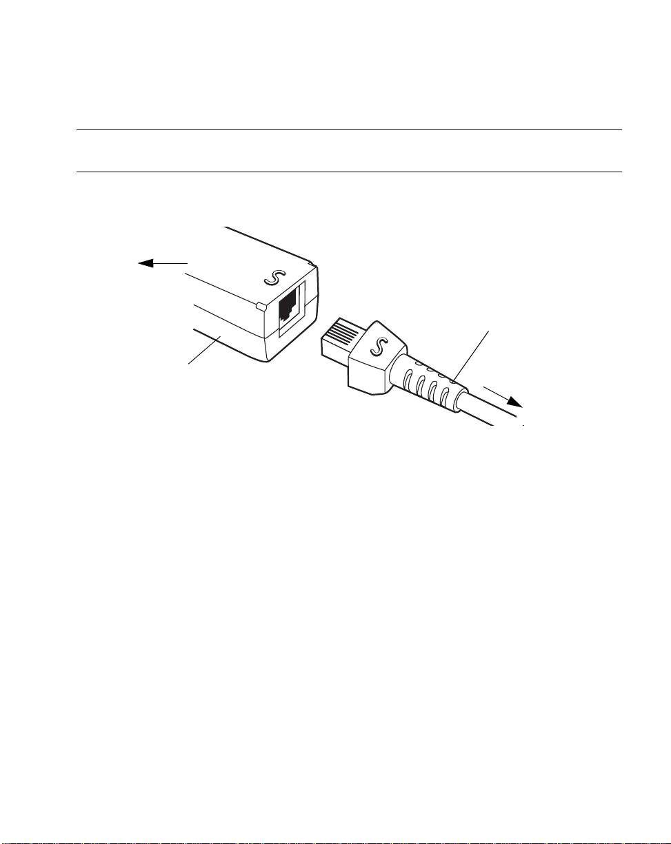
Connecting a Synapse Cable Interface
Note:See the Synapse Inter face Guide provided with your Synapse cable
for detailed setup instructions.
Symbol’s Synapse Smart Cables enable interfacing to a variety of hosts. The appropriate
Synapse cable has the built-in intelligence to detect the host to which it is connected.
To host
Synapse adapter cable
Synapse Smart Cable
To scanner
Figure 1-3. Synapse Cable Connection
1. Plug the Synapse adapter cable (p/n
25-32463-xx) into the bottom of the scanner,
as described in Installing the Interface Cable on page 1-3.
2. Align the ‘S’ on the Synapse adapter cable with the ‘S’ on the Synap se Smart Cable
and plug the cable in.
3. Connect the other end of the Synapse Smart Cable to the host.
Removing the Interface Cable
To remove the interface cable:
1. Unplug the installed cable’s modular connector by depressing the connector clip
with the tip of a screwdriver.
2. Carefully slide out the cable.
3. Follow the steps for Installing the Interface Cable on page 1-3 to connect a new
cable.
1-5
Page 25

LS2100/LS2108 Product Reference Guide
1-6
Page 26
Chapter 2
Scanning
Introduction
This chapter covers the techniques involved in scanning bar codes, beeper and LED
definitions, and general instructions and tips about scanning.
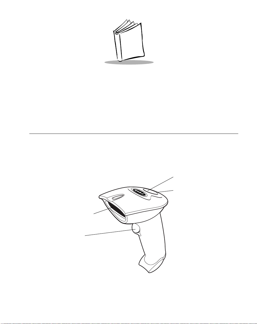
LED
Beeper
Exit Window
Trigger
Figure 2-1. Scanner Parts
2-1
Page 27

LS2100/LS2108 Product Reference Guide
Beeper Definitions
The scanner communicates with the user by emitting different beeper sequences and
patterns. Table 2-1 defines beep sequences that occur during both normal scanning and
while programming the scanner.
Table 2-1. Standard Beeper Definitions
Beeper Sequence Indication
Standard Use
Low/medium/high beep Power up.
Short high beep A bar code symbol was decoded (if decode beeper
is enabled).
4 long low beeps A transmission error was detected in a scanned
symbol. The data is ignored. This occurs if a unit is
not properly configured. Check option setting.
5 low beeps Conversion or format error.
Lo/hi/lo beep ADF transmit error.
Hi/hi/hi/lo beep RS-232 receive error.
Parameter Menu Scanning
Short high beep Correct entry scanned or correct menu sequence
performed.
Lo/hi beep Input error, incorrect bar code or “Cancel” scanned,
wrong entry, incorrect bar code programming
sequence; remain in program mode.
Hi/lo beep Keyboard parameter selected. Enter value using
bar code keypad.
2-2
Hi/lo/hi/lo beep Successful program exit with change in the
parameter setting.
Low/hi/low/hi beep Out of host parameter storage space. Scan Set
Default Parameter on page 4-4.
Code 39 Buffering
Hi/lo beep New Code 39 data was entered into the buffer.
3 Beeps - long high beep Code 39 buffer is full.
Page 28

Scanning
Table 2-1. Standard Beeper Definitions (Continued)
Beeper Sequence Indication
Lo/hi/lo beep The Code 39 buffer was erased or there was an
attempt to clear or transmit an empty buffer.
Lo/hi beep A successful transmission of buffered data.
Host Specific
USB only
4 short high beeps Scanner has not completed initialization. Wait
several seconds and scan again.
Scanner gives a power-up
beep after scanning a USB
Device Type.
This power-up beep occurs
more than once.
RS-232 only
1 short high beep A <BEL> character is received and Beep on <BEL>
Communication with the bus must be established
before the scanner can operate at the highest
power level.
The USB bus may put the scanner in a state where
power to the scanner is cycled on and off more than
once. This is normal and usually happens when the
PC cold boots.
is enabled.
2-3
Page 29

LS2100/LS2108 Product Reference Guide
LED Definitions
In addition to beeper sequences, the scanner communicates with the user using a two-color
LED display. Table 2-2 defines LED colors that display during scanning.
Table 2-2. Standard LED Definitions
LED Indication
Off No power is applied to the scanner, or the scanner
is on and ready to scan.
Green A bar code was successfully decoded.
Red LS 2108 - A data transmission error or scanner
malfunction occurred.
LS 2100 (undecoded) - The red LED will not be lit.
Any user feedback will be provided by the interface
controller.
2-4
Page 30
Scanning
Scanning in Hand-Held Mode
Install and program your scanner. (Refer to each host chapter and Chapter 4, User
Preferences, Chapter 11, Symbologies, Chapter 12, Miscellaneous Scanner Options, and
Chapter 13, Advanced Data Formatting for instructions on programming your scanner.) If
you need assistance, contact your local supplier or your local Symbol Support Center.
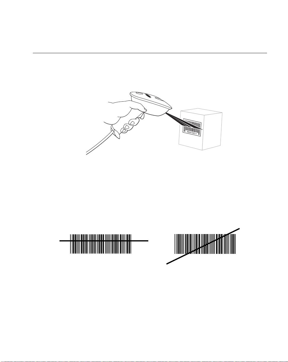
Figure 2-2. Scanning in Hand-Held Mode
1. Ensure all connections are secure. (Refer to the host chapter for your scanner.)
2. Aim the scanner at the bar code. If your scanner has a trigger, aim and press the
trigger.
3. Ensure the scan line crosses every bar and space of the symbol.
RIGHT
012345
4. Upon successful decode, the scanner beeps and the LED turns green. (For more
information on beeper and LED definitions, refer to Table 2-1 and Table 2-2.)
WRONG
012345
2-5
Page 31

LS2100/LS2108 Product Reference Guide
Aiming
Do not hold the scanner directly over the bar code. Laser light reflecting directly back into
the scanner from the bar code is known as spec ular reflection. This specular reflection can
make decoding difficult.
Y ou can tilt the scanner up to 65° forward or back and achieve a successfu l decode (Figure
2-3). Simple practice quickly shows what tolerances to work within.
Specular
Reflection
+ 3
65
Code
65
Bar
Figure 2-3. Maximum Tilt Angles and Dead Zone
2-6
Page 32

Scanning
Scanning in Hands-Free Mode
The optional Intellistand adds greater flexibility to your scanning operation.
Scanning in the Hands-Free Mode(LS2108)
When the scanner is seated in the stand’s “cup ”, the scanner’s built-in sensor places the
scanner in Intellistand mode. When the scanner is removed from the stand it operates in its
normal hand-held mode.
Scanner Holder
(Front)
Figure 2-4. Inserting and Using the Scanner in the Stand
Intellistand operation:
1. Ensure all cable connections are secure.
2. Insert the scanner in the optional hands-free stand by placing the front of the
scanner into the stand’s “cup” (see Figure 2-4). When not in use, th e sca nn e r’s
laser is in a blinking state.
3. To scan a bar code, present the bar code and ensure the scan line crosses every
bar and space of the symbol. The scan beam becomes steady when the scanner
detects the bar code.
Scanner Holder
(Back)
2-7
Page 33

LS2100/LS2108 Product Reference Guide
4. Upon successful decode, the scanner beeps and the LED turns green.
2-8
Page 34

Chapter 3
Maintenance and Technical Specifications
Introduction
This chapter covers suggested scanner maintenance, troubleshooting, technical
specifications, and signal descriptions (pinouts).
Maintenance
Cleaning the exit window is the only maintenance required. A dirty window may affect
scanning accuracy.
• Do not allow any abrasive material to touch the window
• Remove any dirt particles with a damp cloth
• Wipe the window using a tissue moistened with ammonia/water
• Do not spray water or other cleaning liquids directly into the window.
3-1
Page 35

LS2100/LS2108 Product Reference Guide
Troubleshooting
Problem Possible Causes Possible Solutions
Nothing happens when
you follow the operating
instructions, or the
scanner displays erratic
behavior (laser does not
come on, scanner emits
frequent beeps).
No power to the scanner. Check the system power. Ensure the
Table 3-1. Troubleshooting
power supply is connected if your
configuration requires a power supply.
Laser comes on, but
symbol does not decode.
Symbol is decoded, but
not transmitted to the
host.
Interface/power cables are
loose.
Scanner is not programmed
for the correct bar code type.
Bar code symbol is
unreadable.
Distance between scanner
and bar code is incorrect.
Scanner is not programmed
for the correct host type.
Check for loose cable connections.
Be sure the scanner is programmed to
read the type of bar code you are
scanning.
Check the symbol to make sure it is not
defaced. Try scanning test symbols of
the same bar code type.
Move the scanner closer to or further
from the bar code.
Scan the appropriate host type bar code.
3-2
Page 36

Problem Possible Causes Possible Solutions
Scanned data is
incorrectly displayed on
the host.
Note:If after performing these checks the symbol still does not scan,
contact your distributor or call the local Symbol Support Center. See
page xiv for the telephone numbers.
Maintenance and Technical Specifications
Table 3-1. Troubleshooting (Continued)
Scanner is not programmed to
work with the host. Check
scanner host type parameters
or editing options.
Be sure proper host is selected. (See the
host chapter for your scanner.)
For RS-232, ensure the scanner’s
communication parameters match the
host’s settings.
For a USB HID keyboard or a keyboard
wedge configuration, ensure the system
is programmed for the correct keyboard
type and language, and the CAPS LOCK
key is in the correct state.
Be sure editing options (e.g., ADF, UPCE to UPC-A Conversion) are properly
programmed.
3-3
Page 37

LS2100/LS2108 Product Reference Guide
Technical Specifications
Table 3-2. Technical Specifications
Item Description
Power Requirements
Stand-By Current 500mA (max)
Power Source Decoded:
Decode Capability
Beeper Operation User-selectable: Enable, Disable
Beeper Volume User-selectable: three levels
Undecoded:
4.75 – 14 VDC @ approximately 100 mA
(nominal)
Decoded:
5 VDC + / - 10% @ approximately 200mA
(nominal)
Depending on host:
• Host powered
• External power supply
• Battery box:
Converts a 9 Volt battery to a 5 Volt battery
Undecoded:
Power supplied by interface controller
Decoded:
UPC/EAN, UPC/EAN with supplementals, UCC/EAN
128, Code 39, Code 39 Full ASCII, Code 39 Trioptic,
Codabar (NW7), Interleaved 2 of 5, Discrete 2 of 5,
Code 128, Code 93, MSI, Code 11, UCC/EAN RSS,
Code 32, Coupon Code, and Bookland EAN
Undecoded:
Determined by interface controller
Beeper Tone User-selectable: three tones
Scan Repetition Rate 35 ± 5 scans/second
Skew Tolerance ± 60° from nominal
Pitch Tolerance ± 65° from nominal
Roll T o leran ce ± 30° from nominal
3-4
Page 38

Maintenance and Technical Specifications
Table 3-2. Tec hnical Specifications (Continued)
Item Description
Print Contrast Minimum 25% minimum reflectance differential, measured at
650 nm.
Ambient Light Immunity
Indoor:
Outdoor:
Durability 5 ft (1.5 m) drops to concrete
Operating Temperature 32° to 104° F (0° to 40° C)
Storage Temperature -40° to 140° F (-40° to 60° C)
Humidity 5% to 95% (non-condensing)
450 Ft Candles (4,842 Lux) (indoor)
10,000 Ft Candles (107,600 Lux) (outdoor)
Weight (without cable)
Dimensions:
Height
Width
Depth
Laser
Laser Classifications LS2108-I000 and LS2100
ESD 15 kV area discharge
Minimum Element Width 5 mil (0.127 mm)
Interfaces Supported
5.6 oz. (160 g)
6.7 in. (17.0 cm)
2.8 in. (7.1 cm)
3.4 in. (8.6 cm)
650nm laser diode
IEC Class 1
IEC 825-1 Class 2
8 kV contact discharge
Decoded:
RS-232, Keyboard Wedge, Wand Emulation, IBM
468X/469X, USB, Synapse
Undecoded:
Determined by interface controller
3-5
Page 39

LS2100/LS2108 Product Reference Guide
Scanner Signal Descriptions
Bottom of scanner
Cable interface port
PIN 10
Interface cable
modular connector
Figure 3-1. Scanner Cable Pinouts
PIN 1
3-6
Page 40

Maintenance and Technical Specifications
The signal descriptions in Table 3-3 apply to the connector on the scanner and are for
reference only.
Table 3-3. Scanner Signal Pin-outs
LS2100 LS2108
Keyboard
Pin IBM Synapse RS-232
1 Reserved Reserved SynClock Reserved Reserved Reserved Jump to Pin 6
2 Power Power Power Power Power Power Power
3 Ground Ground Ground Ground Ground Ground Ground
4 Enable IBM_A(+) Reserved TxD KeyClock DBP Reserved
5 SOS* Reserved Reserved RxD TermData CTS D +
6 Trigger* IBM_B(-) SynData RTS KeyData RTS Jump to Pin 1
7 Decode Reserved Reserved CTS TermClock Reserved D -
8 DBP* Reserved Reserved Reserved Reserved Reserved Reserved
9 Reserved Reserved Reserved Reserved Reserved Reserved Reserved
10 Reserved Reserved Reserved Reserved Reserved Reserved Reserved
Wedge Wand USB
3-7
Page 41

LS2100/LS2108 Product Reference Guide
3-8
Page 42

Chapter 4
User Preferences
Introduction
You have the option to program the LS 2108 scanner to perform various functions, or
activate different features. This chapter describes each user preference feature and
provides the programming bar codes necessary for selecting these features for your LS
2108 scanner. For the undecoded LS 2100 scanner, refer to the programming guide for
your external interface controller or portable terminal. Before programming, follow the
instructions in Chapter 1, Getting Started.
Your LS 2108 is shipped with the settings shown in the User Preferences Default Table on
page 4-3 (also see Appendix A, Standard Default Parameters for all host device and
miscellaneous scanner defaults). If the default values suit your requ irements, programming
may not be necessary.
Features values are set by scanning single bar codes or short bar code sequences. The
settings are stored in non-volatile memory and are preserved even when the scanner is
powered down.
4-1
Page 43

LS2100/LS2108 Product Reference Guide
If you are not using a Synapse or USB cable you must select a host type (see each host
chapter for specific host information). After you hear the power-up beeps, select a host
type. This only needs to be done once, upon the first power-up when connected to a new
host.
To return all features to their default values, all you ne ed to do is scan the Se t All Defa ults
bar code on page 4-4. Throughout the programming bar code menus, default values are
indicated with asterisks (
*).
* Indicates Default
*High Frequency
Feature/Option
Scanning Sequence Examples
In most cases you need only scan one bar code to set a specific parameter value. For
example, if you want to set the beeper tone to high, simply scan the High Frequency
(beeper tone) bar code listed under Beeper Tone on page 4-5. The scanner issues a short
high beep and the LED turns green, signifying a succe ssf ul parame ter en tr y.
Other parameters, such as specifying Serial Response Time-Out or setting Data
Transmission Formats, require that you scan several bar codes. Refer to Host Serial
Response Time-out on page 6-17 and Scan Data Options on page 12-6 for descriptions of
this procedure.
Errors While Scanning
Unless otherwise specified, if you make an error during a scanning sequence , just re-scan
the correct parameter.
4-2
Page 44

User Preferences
User Preferences Default Parameters
Table 4-1 lists the defaults for user preferences parameters. If you wish to change any
option, scan the appropriate bar code(s) provided in the User Preferences section
beginning on page 4-4.
Note:See Appendix A, Standard Default Parameters for all user
preferences, hosts, symbologies, and miscellaneous default
parameters.
Table 4-1. User Preference s De fa u lt Table
Page
Parameter Default
User Preferences
Set Default Parameter All Defaults 4-4
Number
Beeper Tone High 4-5
Beeper Volume High 4-6
Laser On Time 3.0 Sec 4-7
Beep After Good Decode Enable 4-8
4-3
Page 45

LS2100/LS2108 Product Reference Guide
User Preferences
Set Default Parameter
Scanning this bar code returns all parameters to the default values listed in Table A-1 on
page A-1.
Set All Defaults
4-4
Page 46

User Preferences
Beeper Tone
T o select a decode be ep frequency (tone), scan the Low Frequency, Medium Frequency,
or High Frequency bar code.
Low Frequency
Medium Frequency
*High Frequency
4-5
Page 47

LS2100/LS2108 Product Reference Guide
Beeper Volume
To select a beeper volume, scan the Low Volume, Medium Volume, or High Volume bar
code.
Low Volume
Medium Volume
4-6
*High Volume
Page 48

User Preferences
Laser On Time
This parameter sets the maximum time that decode processing continues during a scan
attempt. It is programmable in 0.1 second incre ments from 0.5 to 9.9 seconds. The default
Laser On Time is 3.0 seconds.
To set a Laser On Time, scan the bar code below. Next, scan two numeric bar codes
beginning on page D-1 in Appendix D that correspond to the desired on time. Single digit
numbers must have a leading zero. For example, to set an On Time of 0.5 seconds, scan
the bar code below , then scan the “0” and “5” bar codes. If you make an error, or wish to
change your selection, scan Cancel on page D-5.
Laser On Time
4-7
Page 49

LS2100/LS2108 Product Reference Guide
Beep After Good Decode
Scan a bar code below to select whether or not the scanner beep s a fter a good decode. If
Do Not Beep After Good Decode is selected, the beeper still operates during parameter
menu scanning and indicates error conditions.
*Beep After Good Decode
(Enable)
4-8
Do Not Beep After Good Decode
(Disable)
Page 50

Chapter 5
Keyboard Wedge Interface
Introduction
This chapter covers Keyboard Wedge interface information for setting up your scanner.
This interface type is used to attach the scanne r between the keyboard and host computer .
The scanner translates the bar code data into keystrokes. The host computer accepts the
keystrokes as if they originate from the keyboard.
This mode of operation allows adding bar code reading functionality to a system designed
for manual keyboard input. In this mode the keyboard keystrokes are simply passed
through.
Throughout the programming bar code menus, default values are indicated with asterisks
(
*).
* Indicates Default
*North American
Feature/Option
5-1
Page 51

LS2100/LS21008 Product Reference Guide
Connecting a Keyboard Wedge Interface
Male DIN Keyboard Connector to Host Connector to Host
Y-cable
Power supply
(if needed)
Figure 5-1. Keyboard Wedge Connection with Y-cable
To connect the Keyboard Wedge Y-cable:
1. Switch off the host and unplug the keyboard connector.
2. Attach the modular connector of the Y-cable to the cable interface port on the
scanner. (See Installing the Interface Cable on page 1-3.)
3. Connect the round male DIN host connector of the Y-cable to the keyboard port on
the host device.
4. Connect the round female DIN keyboard connector of the Y-cable to the keyboard.
5. If needed, attach the optional power supply to the conne ctor in the mid dle of the Ycable.
6. Ensure that all connections are secure.
7. Switch on your host system.
8. Scan the appropriate bar codes in this chapter to configure the scanner.
5-2
Page 52

Keyboard Wedge Interface
Keyboard Wedge Default Parameters
T able 5- 1 lists the defaults for Keyboard W edge host parameters. If you wish to chan ge any
option, scan the appropriate bar code(s) pro vided in the Keyboard Wedge Host Parameters
section beginning on page 5-4.
Note:See Appendix A, Standard Default Parameters for all user
preferences, hosts, symbologies, and miscellaneous default
parameters.
Table 5-1. Keyboard Wedge Host Default Table
Page
Parameter Default
Keyboard Wedge Host Parameters
Number
Keyboard Wedge Host Type IBM PC/AT & IBM PC
Compatibles
Country Types (Country Codes) North American 5-6
Ignore Unknown Characters Ignore 5-8
Keystroke Delay No Delay 5-9
Intra-Keystroke Delay Disable 5-10
Alternate Numeric Keypad Emulation Disable 5-10
Caps Lock On Disable 5-11
Caps Cancel Override Disable 5-12
1
User selection is required to configure this interface and this is the most common selection.
1
5-4
5-3
Page 53

LS2100/LS21008 Product Reference Guide
Keyboard Wedge Host Types
Keyboard Wedge Host Types
Select your keyboard wedge host by scanning one of the bar codes below.
IBM PC/AT & IBM PC Compatibles
IBM PS/2 (Model 30)
IBM AT NOTEBOOK
IBM XT
1
5-4
NCR 7052
Page 54

Keyboard Wedge Interface
Note:1User selection is required to configure this interface and this is the
most common selection.
5-5
Page 55

LS2100/LS21008 Product Reference Guide
Keyboard Wedge Country Types (Country Codes)
Scan the bar code corresponding to your keyboard type. If your particular keyboard type is
not listed, see Alternate Numeric Keypad Emulation on page 5-10.
*North American
German
5-6
French
French Canadian
Page 56

Keyboard Wedge Interface
Keyboard Wedge Country Types (continued)
Spanish
Italian
Swedish
UK English
Japanese
5-7
Page 57

LS2100/LS21008 Product Reference Guide
Ignore Unkown Characters
Unknown characters are characters the host does not recognize. Wh en Send Bar Code s
With Unknown Characters is selected, all bar code data is sent except for unknown
characters, and no error beep s sound on the scanner . When Do Not Send Bar Codes With
Unknown Characters is selected, bar code data is sent up to the first unknown character
and then four (error) beeps sound on the scanner.
*Send Bar Codes With Unknown
Do Not Send Bar Codes with Unknown Characters
Characters
(Transmit)
5-8
Page 58

Keyboard Wedge Interface
Keystroke Delay
This is the delay in milliseconds between emulated keystrokes. Scan a bar code below to
increase the delay when hosts require a slower transmission of data.
*No Delay
Medium Delay (20 msec)
Long Delay (40 msec)
5-9
Page 59

LS2100/LS21008 Product Reference Guide
Intra-Keystroke Delay
When enabled, an additional delay is inserted between each emula ted key depression and
release. This sets the Keystroke Delay parameter to a minimum of 5 msec as well.
Enable
*Disable
Alternate Numeric Keypad Emulation
This allows emulation of most other country keyboard types not listed in Keyboard Wedge
Country Types (Country Codes) on page 5-6 in a Microsoft operating system environment.
Enable Alternate Numeric Keypad
*Disable Alternate Numeric Keypad
5-10
Page 60

Keyboard Wedge Interface
Caps Lock On
When enabled, the scanner emulates keystrokes as if the Caps Lock key is always
pressed.
Enable Caps Lock On
*Disable Caps Lock On
5-11
Page 61

LS2100/LS21008 Product Reference Guide
Caps Lock Override
When enabled, on AT or AT Notebook hosts, the keyboard ignores the state of the Caps
Lock key. Therefore, an ‘A’ in the bar code is sent as an ‘A’ no matter what the state of the
keyboard’s Caps Lock key.
Enable Caps Lock Override
*Disable Caps Lock Override
Note:If both Caps Lock On and Caps Lock Override are enabled, Caps
Lock Override takes precedence.
OnKeyboard Maps
The following keyboard maps are provided for prefix/suffix keystroke parameters. To
program the prefix/suffix values, see the bar codes on page12-5.
5-12
Page 62

Keyboard Wedge Interface
7014 5001 5002 5003 5004 5005 5006 5007 5008 5009 5010
7009
Figure 5-2. IBM PS2 Type Keyboard
.
5001
5003
5005
5007
5009
5002
5004
5006
5008
5010
7014
7009
Figure 5-3. IBM PC/XT
5011
7008
7013
7013
5012
7003
7012
7011
7002 7004 7005
7008
7012
7013
7004
7011 7002
7003
7006
5001
5003
5005
5007
5009
5002
5004
5006
5008
5010
7009
Figure 5-4. IBM PC/AT
7008
7013
7014
7012
7004
7011
7003
7002
5-13
Page 63

LS2100/LS21008 Product Reference Guide
5001
5003
5004
5005 5006
5007
5009
1066
1065
1072
1073
1079 1080
5002
5001
5003
5004
5002
5011
5008
5010
1048
5012
1046
(1048 if double key)
Figure 5-5. NCR 7052 32-KEY
1067
1074
1081
5011
1068
1075
1082
1045
5014
1043
5017
7013
(7013 if double key)
1070
1069
1076
1077
1083 1084
1045
5013
5014
5015
5013
5015
5016
5018
5019
1071
1078
1085
1086
1087
5-14
5005 5006
5007
5008
5009
5010
1043
5017
5012
1048
(1048 if double key)
1046
7013
(1043 if double key)
Figure 5-6. NCR 7052 58-KEY
5016
5018
5019
1088
1089
1090
Page 64

ASCII Character Set
Note:Code 39 Full ASCII interprets the bar code special character
($ + % /) preceding a Code 39 character and assigns an ASCII
character value to the pair . For example, when Code 39 Full ASCII
is enabled and a +B is scanned, it is interpreted as b, %J as ?, and
%V as @. Scanning ABC%I outputs the keystroke equivalent of
ABC >.
Table 5-2. Keyboard Wedge ASCII Character Set
Keyboard Wedge Interface
ASCII
Value
1001 $A CTRL A
1002 $B CTRL B
1003 $C CTRL C
1004 $D CTRL D
1005 $E CTRL E
1006 $F CTRL F
1007 $G CTRL G
1008 $H CTRL H
1009 $I CTRL I
1010 $J CTRL J
1011 $K CTRL K
1012 $L CTRL L
1013 $M CTR L M
1014 $N CTRL N
1015 $O CTRL O
1016 $P CTRL P
Full ASCII
Code 39
Encode Char.
Keystroke
1017 $Q CTRL Q
5-15
Page 65

LS2100/LS21008 Product Reference Guide
Table 5-2. Keyboard Wedge ASCII Character Set (Continued)
1018 $R CTRL R
1019 $S CTRL S
1020 $T CTRL T
1021 $U CTRL U
1022 $V CTRL V
1023 $W CTRL W
1024 $X CTRL X
1025 $Y CTRL Y
1026 $Z CTRL Z
1032 Space Space
1033 /A !
1034 /B ‘
1035 /C #
1036 /D E
1037 /E %
5-16
1038 /F &
1039 /G ‘
1040 /H (
1041 /I )
1042 /J *
1043 /K +
1044 /L ,
1045 - 1046 . .
1047 / /
1048 0 0
1047 1 1
Page 66

Keyboard Wedge Interface
Table 5-2. Keyboard Wedge ASCII Character Set (Continued)
1050 2 2
1051 3 3
1052 4 4
1053 5 5
1054 6 6
1055 7 7
1056 8 8
1057 9 9
1058 /Z :
1059 %F ;
1060 %G <
1061 %H =
1062 %I >
1063 %J ?
1064 %V @
1065 A A
1066 B B
1067 C C
1068 D D
1069 E E
1070 F F
1071 G G
1072 H H
1073 I I
1074 J J
1075 K K
1076 L L
5-17
Page 67

LS2100/LS21008 Product Reference Guide
Table 5-2. Keyboard Wedge ASCII Character Set (Continued)
1077 M M
1078 N N
1079 O O
1080 P P
1081 Q Q
1082 R R
1083 S S
1084 T T
1085 U U
1086 V V
1087 W W
1088 X X
1089 Y Y
1090 Z Z
1091 %K [
5-18
1092 %L \
1093 %M ]
1094 %N ^
1095 %O _
1096 %W ‘
1097 +A a
1098 +B b
1099 +C c
1100 +D d
1101 +E e
1102 +F f
1103 +G g
Page 68

Keyboard Wedge Interface
Table 5-2. Keyboard Wedge ASCII Character Set (Continued)
1104 +H h
1105 +I i
1106 +J j
1107 +K k
1108 +L l
1109 +M m
1110 +N n
1111 +O o
1112 +P p
1113 +Q q
1114 +R r
1115 +S s
1116 +T t
1117 +U u
1118 +V v
1119 +W w
1120 +X x
1121 +Y y
1122 +Z z
1123 %P {
1124 %Q |
1125 %R }
1126 %S ~
1127 Undefined
1128
ALT Keys Keystroke
2065 ALT A
5-19
Page 69

LS2100/LS21008 Product Reference Guide
Table 5-2. Keyboard Wedge ASCII Character Set (Continued)
2066 ALT B
2067 ALT C
2068 ALT D
2069 ALT E
2070 ALT F
2071 ALT G
2072 ALT H
2073 ALT I
2074 ALT J
2075 ALT K
2076 ALT L
2077 ALT M
2078 ALT N
2079 ALT O
2080 ALT P
5-20
2081 ALT Q
2082 ALT R
2083 ALT S
2084 ALT T
2085 ALT U
2086 ALT V
2087 ALT W
2088 ALT X
2089 ALT Y
2090 ALT Z
PF Keys Keystrokes
4001 PF 1
Page 70

Keyboard Wedge Interface
Table 5-2. Keyboard Wedge ASCII Character Set (Continued)
4002 PF 2
4003 PF 3
4004 PF 4
4005 PF 5
4006 PF 6
4007 PF 7
4008 PF 8
4009 PF 9
4010 PF 10
4011 PF 11
4012 PF 12
4013 PF 13
4014 PF 14
4015 PF 15
4016 PF 16
4017 PF 17
4018 PF 18
4019 PF 19
4020 PF 20
4021 PF 21
4022 PF 22
4023 PF 23
4024 PF 24
F Keys Keystroke
5001 F1
5002 F2
5003 F3
5-21
Page 71

LS2100/LS21008 Product Reference Guide
Table 5-2. Keyboard Wedge ASCII Character Set (Continued)
5004 F4
5005 F5
5006 F6
5007 F7
5008 F8
5009 F9
5010 F10
5011 F11
5012 F12
5013 F13
5014 F14
5015 F15
5016 F16
5017 F17
5018 F18
5-22
5019 F19
5020 F20
5021 F21
5022 F22
5023 F23
5024 F24
5025 F25
5026 F26
5027 F27
5028 F28
5029 F29
5030 F30
Page 72

Keyboard Wedge Interface
Table 5-2. Keyboard Wedge ASCII Character Set (Continued)
5031 F31
5032 F32
5033 F33
5034 F34
5035 F35
5036 F36
5037 F37
5038 F38
5039 F39
5040 F40
Numeric
Keypad
6042 *
6043 +
6044 undefined
6045 6046 .
6047 /
6048 0
6049 1
6050 2
6051 3
6052 4
6053 5
6054 6
6055 7
6056 8
Keystroke
5-23
Page 73

LS2100/LS21008 Product Reference Guide
Table 5-2. Keyboard Wedge ASCII Character Set (Continued)
6057 9
6058 Enter
6059 Num Lock
Extended
Keypad
7001 Break
7002 Delete
7003 Pg Up
7004 End
7005 Pg Dn
7006 Pause
7007 Scroll Lock
7008 Backspace
7009 Tab
7010 Print Screen
7011 Insert
7012 Home
7013 Enter
7014 Escape
7015 Up Arrow
7016 Dn Arrow
Keystroke
5-24
7017 Left Arrow
7018 Right Arrow
Page 74

Chapter 6
RS-232 Interface
Introduction
This chapter covers RS-232 host information for setting up your scanner. The RS-232
interface is used to attach the scanner to point-of-sale devices, host computers, or other
devices with an available RS-232 port (e.g., com port).
If your particular host is not listed in Table 6-2, you need to set the communicati on
parameters to match your host device. To set communication parameters for hosts not
listed, refer to the documentation for the host device.
Throughout the programming bar code menus, default values are indicated with asterisks
(
*).
* Indicates Default
*Baud Rate 9600
Feature/Option
6-1
Page 75

LS2100/LS2108 Product Reference Guide
Connecting an RS-232 Interface
This connection is made directly from the scanner to the host computer.
Serial Port Connector to Host
Power supply cable
Interface cable
Interface cable
Power supply
Figure 6-1. RS-232 Direct Connection
1. Connect the RS-232 interface cable to the bottom of the scanner, as described in
Installing the Interface Cable on page 1-3.
2. Connect the other end of the interface cable to the serial port on the host.
3. Connect the power supply.
4. Scan appropriate bar codes in this chapter to match your host settings.
RS-232 Default Parameters
Table 6-1 lists the defaults for RS-232 host parameters. If you wish to change any option,
scan the appropriate bar code(s) provided in the Parameter Descriptions section beginning
on page 6-4.
6-2
Page 76

Note:See Appendix A, Standard Default Parameters for all user
preferences, hosts, symbologies, and miscellaneous default
parameters.
Table 6-1. RS-232 Host Default Table
Parameter Default
RS-232 Host Parameters
RS-232 Interface
Page
Number
RS-232 Host Types Standard
Baud Rate 9600 6-9
Parity Type None 6-1 1
Check Receive Errors Enable 6-12
Hardware Handshaking None 6-14
Software Handshaking None 6-15
Host Serial Response Time-out 2 Sec 6-17
RTS Line State Low RTS 6-18
Stop Bit Select 1 6-19
ASCII Format 8-Bit 6-19
Beep on <BEL> Disable 6-20
Intercharacter Delay 0 msec 6-21
1
User selection is required to configure this interface and this is the most common selection.
1
6-6
6-3
Page 77

LS2100/LS2108 Product Reference Guide
RS-232 Host Parameters
Various RS-232 hosts are set up with their own parameter default settings (Table 6-2).
Selecting the ICL, Fujitsu, Wincor-Nixdorf Mode A, Wincor-Nixdorf Mode B, Olivetti, or
Omron terminal sets the defaults listed below. These defaults take precedence over
standard defaults and remain selected if the Set Defaults bar code is scanned.
Table 6-2. Terminal Specific RS-232
Wincor-
Wincor-
Standard
Parameter
Transmit Code ID No Yes Yes Yes Yes
Data
Transmission
Format
Suffix CR/LF
Baud Rate 9600 9600 9600 9600 9600
Parity None Even None Odd Odd
Hardware
Handshaking
Software
Handshaking
Serial Response
Time-out
Stop Bit Select One One One One One
ASCII Format 8-Bit 8-Bit 8-Bit 8-Bit 8-Bit
Beep On <BEL> Disable Disable Disable Disable Disable
RTS Line State Low High Low Low Low = No data
(Default) ICL Fujitsu
Data as is Data/Suffix Data/Suffix Data/Suffix Data/Suffix
CR (1013) CR (1013) CR (1013) CR (1013)
(7013)
None RTS/CTS
Option 3
None None None None None
2 Sec. 9.9 Sec. 2 Sec. 9.9 Sec. 9.9 Sec.
None RTS/CTS
Nixdorf
Mode A
Option 3
Nixdorf
Mode B/
OPOS
RTS/CTS
Option 3
to send
6-4
Page 78

RS-232 Interface
RS-232 Host Parameters (continued)
Selecting the ICL, Fujitsu, Wincor-Nixdorf Mode A, Wincor-Nixdorf Mode B, OPOS terminal
enables the transmission of code ID characters listed in Table 6-3 below. These code ID
characters are not programmable and are sep arate from the T ransmit Code ID feature. The
Transmit Code ID feature should not be enabled for these terminals.
Table 6-3. Terminal Specific Code ID Characters
Wincor-
Nixdorf
ICL Fujitsu
UPC-A A A A0 A0
UPC-E EEC0C0
EAN-8 FF FF B B
EAN-13 FFA A
Code 39 C <len> None M M
Codabar N <len> None N N
Code 128 L <len> None K K
I 2 of 5 I <len> None I I
Code 93 None None L L
D 2 of 5 H <len> None H H
UCC/EAN 128 L <len> None P P
MSI None None O O
Bookland EAN FFA A
Trioptic None None None None
Code 11 None None None None
RSS 14 None None None E
RSS Limited None None None E
RSS Expanded None None None E
Mode A
Wincor-
Nixdorf
Mode B/OPOS
6-5
Page 79

LS2100/LS2108 Product Reference Guide
RS-232 Host Types
To select an RS-232 host interface, scan one of the following bar codes.
Standard RS-232
ICL RS-232
Wincor-Nixdorf RS-232 Mode A
1
Wincor-Nixdorf RS-232 Mode B
Note:1User selection is required to configure this interface and this is the
most common selection.
6-6
Page 80

RS-232 Host Interfaces (continued)
OPOS
Fujitsu RS-232
RS-232 Interface
6-7
Page 81

LS2100/LS2108 Product Reference Guide
Baud Rate
Baud rate is the number of bits of data transmitted per second. The scanner's baud rate
setting should match the baud rate setting of the host device. If not, dat a may not reach the
host device or may reach it in distorted form.
Baud Rate 600
Baud Rate 1200
6-8
Baud Rate 2400
Baud Rate 4800
Page 82

Baud Rate (continued)
Baud Rate 9600
*
Baud Rate 19,200
RS-232 Interface
Baud Rate 38,400
6-9
Page 83

LS2100/LS2108 Product Reference Guide
Parity
A parity check bit is the most significant bit of each ASCII coded character . Select the parity
type according to host device requirements.
Select Odd parity and the parity bit value is set to 0 or 1, base d on dat a, to ensure th at an
odd number of 1 bits are conta ined in the coded character.
Odd
Select Even parity and the parity bit value is set to 0 or 1, based on data, to ensure that an
even number of 1 bits are contained in the coded character.
Even
Select Mark parity and the parity bit is always 1.
Mark
6-10
Page 84

Parity (continued)
Select Space parity and the parity bit is always 0.
Space
Select None when no parity bit is required.
*None
RS-232 Interface
6-11
Page 85

LS2100/LS2108 Product Reference Guide
Check Receive Errors
Select whether or not the parity, framing, and overrun of received char acters are checke d.
The parity value of received characters is verified against the parity parameter selected
above.
*Check For Received Errors
Do Not Check For Received Errors
6-12
Page 86

RS-232 Interface
Hardware Handshaking
The data interface consists of an RS-232 port designed to operate either with or without the
hardware handshaking lines, Request to Send (RTS), and Clear to Send (CTS).
If Standard RTS/CTS handshaking is not selected, scan data is transmitted as it becomes
available. If Standard RTS/CTS handshaking is selected, scan data is transmitted
according to the following sequence:
• The scanner reads the CTS line for activity. If CTS is asserted, the scanner waits
up to 2 seconds for the host to negate the CTS line. If, after 2 seconds (default),
the CTS line is still asserted, the scanner sounds a transmit error, and any scanned
data is lost.
• When the CTS line is negated, the scanner asserts the R TS line and wait s up to 2
seconds for the host to assert CTS. When the host asserts CTS, data is
transmitted. If, after 2 seconds (default), the CTS line is not asserted, the scanner
sounds a transmit error, an d discards the data.
• When data transmission is complete, the scanner negates RTS 10 msec after
sending the last character.
• The host should respond by negating CTS. The scanner checks for a negated CTS
upon the next transmission of data.
During the transmission of data, the CTS line should b e asserted. If CTS is deasser ted for
more than 50 ms between characters, the transmission is aborted, the scanner sounds a
transmission error, and the data is discarded.
If the above communications sequence fails, the scanner issues an e rror indication. In this
case, the data is lost and must be rescanned.
If Hardware Handshaking and Software Handshaking are both enabled, Hardware
Handshaking takes precedence.
Note:The DTR signal is jumpered to the active state.
6-13
Page 87

LS2100/LS2108 Product Reference Guide
None
Scan the bar code below if no Hardware Handshaking is desired.
*None
Standard RTS/CTS
Scan the bar code below to select Standard RTS/CTS Hardware Handshaking.
Standard RTS/CTS
RTS/CTS Option 1
When RTS/CTS Option 1 is selected, the scanner asserts RTS before transmitting and
ignores the state of CTS. The scanner de-assert s R TS when the transmission is comp lete.
RTS/CTS Option 1
RTS/CTS Option 2
When Option 2 is selected, RTS is always high or low (user-programmed logic level).
However, the scanner waits for CTS to be asserted before transmitting data. If CTS is not
asserted within 2 seconds (default), the scanner issues an error indication and discards the
data.
RTS/CTS Option 2
6-14
Page 88

RS-232 Interface
RTS/CTS Option 3
When Option 3 is selected, the scanner asserts RTS prior to any data transmission,
regardless of the state of CTS. The scanner wait s up to 2 seconds ( default) fo r CT S to be
asserted. If CTS is not asserted during this time, the scanner issues an error indication and
discards the data. The scanner de-asserts RTS when transmission is complete.
RTS/CTS Option 3
Software Handshaking
This parameter offers control of the data transmissio n process in addition to, or instead of,
that offered by hardware handshaking. There are five options.
If Software Handshaking and Hardware Handshaking are both enabled, Hardware
Handshaking takes precedence.
None
When this option is selected, data is transmitted immediately.
*None
6-15
Page 89

LS2100/LS2108 Product Reference Guide
ACK/NAK
When this option is selected, after transmitting data, the scanner expects either an ACK or
NAK response from the host. When a NAK is received, the scanner tran smits the same data
again and waits for either an ACK or NAK. After three unsuccessful attempts to send data
when NAKs are received, the scanner issues an error indication and discards the data.
The scanner waits up to the programmable Host Serial Response Time-out to receive an
ACK or NAK. If the scanner does not get a resp onse in this time, it issues an error indication
and discards the data. There are no retries when a time-out occurs.
ACK/NAK
ENQ
When this option is selected, the scanner waits for an ENQ character from the host befor e
transmitting data. If an ENQ is not received within the Host Serial Response T ime-out, the
scanner issues an error indication and discards the data. The host must transmit an ENQ
character at least every Host Serial Response Time-out to prevent transmission errors.
ACK/NAK with ENQ
This combines the two previous options.
ACK/NAK with ENQ
6-16
ENQ
Page 90

RS-232 Interface
XON/XOFF
An XOFF character turns the scanner transmission off until the scanner receives an XON
character. There are two situations for XON/XOFF:
• XOFF is received before the scanner has data to sen d. When the scanner has data
to send, it waits up to 2 seconds for an XON character before transmission. If the
XON is not received within this time, the scanner issues an error indication and
discards the data.
• XOFF is received during a transmission. Data transmission then stops after
sending the current byte. When the scanner receives an XON character, it sends
the rest of the data message. The scanner waits indefinitely for the XON.
XON/XOFF
Host Serial Response Time-out
This parameter specifies how long the scanner waits for an ACK, NAK, or CTS before
determining that a transmission error has occurred. This only applies when in one of the
ACK/NAK Software Handshaking modes, or RTS/CTS Hardware Handshaking option.
*Minimum: 2 Sec
Low: 2.5 Sec
6-17
Page 91

LS2100/LS2108 Product Reference Guide
Medium: 5 Sec
High: 7.5 Sec
Maximum: 9.9 Sec
RTS Line State
This parameter sets the idle state of the Serial Host RTS line. Scan a bar code below to
select Low RTS or High RTS line state.
*Host: Low RTS
Host: High RTS
6-18
Page 92

RS-232 Interface
Stop Bit Select
The stop bit(s) at the end of each transmitted character marks the end of transmission of
one character and prepares the receiving device for the next character in the serial data
stream. The number of stop bits selected (one or two) depen ds on the number the receiving
terminal is programmed to accommodate. Set the number of stop bits to match host device
requirements.
*1 Stop Bit
2 Stop Bits
ASCII Format
This parameter allows the scanner to interface with devices requiring a 7-bit or 8-bit ASCII
protocol.
7-Bit
*8-Bit
6-19
Page 93

LS2100/LS2108 Product Reference Guide
Beep on <BEL>
When this parameter is enabled, the scanner issues a beep when a <BEL> character is
detected on the RS-232 serial line. <BEL> is issued to gain a user's attention to an illegal
entry or other important event.
Beep On <BEL> Character
(Enable)
*Do Not Beep On <BEL> Character
(Disable)
6-20
Page 94

RS-232 Interface
Intercharacter Delay
This parameter specifies the intercharacter delay inserted between character
transmissions.
*Minimum: 0 msec
Low: 25 msec
Medium: 50 msec
High: 75 msec
Maximum: 99 msec
6-21
Page 95

LS2100/LS2108 Product Reference Guide
Prefix / Suffix Values
The values in Table 6-4 can be assigned as prefixes or suffixes for ASCII character data
transmission.
Table 6-4. Prefix/Suffix Values
Full ASCII
Prefix/Suffix Value
1000 %U NUL
1001 $A SOH
1002 $B STX
1003 $C ETX
1004 $D EOT
1005 $E ENQ
1006 $F ACK
1007 $G BELL
1008 $H BCKSPC
1009 $I HORIZ TAB
1010 $J LF/NW LN
Code 39 Encode Character ASCII Character
6-22
1011 $K VT
1012 $L FF
1013 $M CR/ENTER
1014 $N SO
1015 $O SI
1016 $P DLE
1017 $Q DC1
1018 $R DC2
1019 $S DC3
1020 $T DC4
1021 $U NAK
Page 96

Prefix/Suffix Value
1022 $V SYN
1023 $W ETB
1024 $X CAN
1025 $Y EM
1026 $Z SUB
1027 %A ESC
1028 %B FS
1029 %C GS
1030 %D RS
1031 %E US
1032 Space Space
1033 /A !
1034 /B "
RS-232 Interface
Table 6-4. Prefix/Suffix Values (Continued)
Full ASCII
Code 39 Encode Character ASCII Character
1035 /C #
1036 /D $
1037 /E %
1038 /F &
1039 /G ‘
1040 /H (
1041 /I )
1042 /J *
1043 /K +
1044 /L ,
1045 -1046 ..
1047 //
6-23
Page 97

LS2100/LS2108 Product Reference Guide
Prefix/Suffix Value
1048 00
1049 11
1050 22
1051 33
1052 44
1053 55
1054 66
1057 77
1056 88
1057 99
1058 /Z :
1059 %F ;
1060 %G <
Table 6-4. Prefix/Suffix Values (Continued)
Full ASCII
Code 39 Encode Character ASCII Character
6-24
1061 %H =
1062 %I >
1063 %J ?
1064 %V @
1065 AA
1066 BB
1067 CC
1068 DD
1069 EE
1070 FF
1071 GG
1072 HH
1073 II
Page 98

Prefix/Suffix Value
1074 JJ
1075 KK
1076 LL
1077 MM
1078 NN
1079 OO
1080 PP
1081 QQ
1082 RR
1083 SS
1084 TT
1085 UU
1086 VV
RS-232 Interface
Table 6-4. Prefix/Suffix Values (Continued)
Full ASCII
Code 39 Encode Character ASCII Character
1087 WW
1088 XX
1089 YY
1090 ZZ
1091 %K [
1092 %L \
1093 %M ]
1094 %N ^
1095 %O _
1096 %W `
1097 +A a
1098 +B b
1099 +C c
6-25
Page 99

LS2100/LS2108 Product Reference Guide
Prefix/Suffix Value
1100 +D d
1101 +E e
1102 +F f
1103 +G g
1104 +H h
1105 +I i
1106 +J j
1107 +K k
1108 +L l
1109 +M m
1110 +N n
1111 +O o
1112 +P p
Table 6-4. Prefix/Suffix Values (Continued)
Full ASCII
Code 39 Encode Character ASCII Character
6-26
1113 +Q q
1114 +R r
1115 +S s
1116 +T t
1117 +U u
1118 +V v
1119 +W w
1120 +X x
1121 +Y y
1122 +Z z
1123 %P {
1124 %Q |
1125 %R }
Page 100

Prefix/Suffix Value
1126 %S ~
1127 Undefined
7013 ENTER
RS-232 Interface
Table 6-4. Prefix/Suffix Values (Continued)
Full ASCII
Code 39 Encode Character ASCII Character
6-27
 Loading...