

Page 1

LS1900 Series
Product Reference Guide
Page 2

LS1900 Series
Product Reference Guide
72-50930-01
Revision A
June 2001
Page 3

© 2001 by Symbol Technologies, Inc. All rights reserved.
No part of this publication may be reproduced or used in any form, or by any electrical or
mechanical means, without permission in writing from Symbol. This includes electronic or
mechanical means, such as photocopying, recording, or information storage and retrieval
systems. The material in this guide is subject to change without notice.
The software is provided strictly on an “as is” basis. All software, including firmware,
furnished to the user is on a licensed basis. Symbol grants to the user a non-transferable
and non-exclusive license to use each software or firmware program delivered hereunder
(licensed program). Except as noted below, such license may not be assigned,
sublicensed, or otherwise transferred by the user without prior written consent of Symbol.
No right to copy a licensed program in whole or in part is granted, except as permitted under
copyright law. The user shall not modify, merge, or incorporate any form or portion of a
licensed program with other program material, create a derivative work from a licensed
program, or use a licensed program in a network without written permission from Symbol.
The user agrees to maintain Symbol’s copyright notice on the licensed programs delivered
hereunder, and to include the same on any authorized copies it makes, in whole or in part.
The user agrees not to decompile, disassemble, decode, or reverse engineer any licensed
program delivered to the user or any portion thereof.
Symbol reserves the right to make changes to any software or product to improve reliability,
function, or design.
Symbol does not assume any product liability arising out of, or in connection with, the
application or use of any product, circuit, or application described herein.
No license is granted, either expressly or by implication, estoppel, or otherwise under any
Symbol Technologies, Inc., intellectual property rights. An implied license only exists for
equipment, circuits, and subsystems contained in Symbol products.
Symbol, Spectrum One, and Spectrum24 are registered trademarks of Symbol
Technologies, Inc. Other product names mentioned in this guide may be trademarks or
registered trademarks of their respective companies and are hereby acknowledged.
Symbol Technologies, Inc.
One Symbol Plaza
Holtsville, New York 11742-1300
http://www.symbol.com
Page 4

Contents
About This Guide
Introduction . . . . . . . . . . . . . . . . . . . . . . . . . . . . . . . . . . . . . . . . . . . . . . . . . . . . . . . . . . . . . . . . . . . .ix
Chapter Descriptions. . . . . . . . . . . . . . . . . . . . . . . . . . . . . . . . . . . . . . . . . . . . . . . . . . . . . . . . . . . . .ix
Notational Conventions . . . . . . . . . . . . . . . . . . . . . . . . . . . . . . . . . . . . . . . . . . . . . . . . . . . . . . . . . . . x
Related Publications . . . . . . . . . . . . . . . . . . . . . . . . . . . . . . . . . . . . . . . . . . . . . . . . . . . . . . . . . . . . . x
Service Information . . . . . . . . . . . . . . . . . . . . . . . . . . . . . . . . . . . . . . . . . . . . . . . . . . . . . . . . . . . . . . x
Symbol Support Center . . . . . . . . . . . . . . . . . . . . . . . . . . . . . . . . . . . . . . . . . . . . . . . . . . . . . . . . . . .xi
LS1900 Series Warranty . . . . . . . . . . . . . . . . . . . . . . . . . . . . . . . . . . . . . . . . . . . . . . . . . . . . . . . . .xiii
LS1900 Series Warranty Coverage and Procedure. . . . . . . . . . . . . . . . . . . . . . . . . . . . . . . . .xiv
General. . . . . . . . . . . . . . . . . . . . . . . . . . . . . . . . . . . . . . . . . . . . . . . . . . . . . . . . . . . . . . . . . . .xiv
Chapter 1. Getting Started
Introduction . . . . . . . . . . . . . . . . . . . . . . . . . . . . . . . . . . . . . . . . . . . . . . . . . . . . . . . . . . . . . . . . . . 1-1
Unpacking Your Scanner. . . . . . . . . . . . . . . . . . . . . . . . . . . . . . . . . . . . . . . . . . . . . . . . . . . . . . . . 1-2
Setting Up the LS1900 Series Scanner. . . . . . . . . . . . . . . . . . . . . . . . . . . . . . . . . . . . . . . . . . . . . 1-3
Installing the Interface Cable . . . . . . . . . . . . . . . . . . . . . . . . . . . . . . . . . . . . . . . . . . . . . . . . . 1-3
Removing the Interface Cable . . . . . . . . . . . . . . . . . . . . . . . . . . . . . . . . . . . . . . . . . . . . . . . . 1-4
Connecting to a Host . . . . . . . . . . . . . . . . . . . . . . . . . . . . . . . . . . . . . . . . . . . . . . . . . . . . . . . 1-4
Chapter 2. Scanning
Introduction . . . . . . . . . . . . . . . . . . . . . . . . . . . . . . . . . . . . . . . . . . . . . . . . . . . . . . . . . . . . . . . . . . 2-1
Beeper Definitions . . . . . . . . . . . . . . . . . . . . . . . . . . . . . . . . . . . . . . . . . . . . . . . . . . . . . . . . . . . . . 2-2
LED Definitions . . . . . . . . . . . . . . . . . . . . . . . . . . . . . . . . . . . . . . . . . . . . . . . . . . . . . . . . . . . . . . . 2-3
Scanning in Hand-Held Mode . . . . . . . . . . . . . . . . . . . . . . . . . . . . . . . . . . . . . . . . . . . . . . . . . . . . 2-4
Scanning with the LS190xx . . . . . . . . . . . . . . . . . . . . . . . . . . . . . . . . . . . . . . . . . . . . . . . . . . 2-4
Aiming . . . . . . . . . . . . . . . . . . . . . . . . . . . . . . . . . . . . . . . . . . . . . . . . . . . . . . . . . . . . . . . . . . . . . . 2-5
Decode Zones . . . . . . . . . . . . . . . . . . . . . . . . . . . . . . . . . . . . . . . . . . . . . . . . . . . . . . . . . . . . . . . . 2-6
Scanning in Hands-Free Mode . . . . . . . . . . . . . . . . . . . . . . . . . . . . . . . . . . . . . . . . . . . . . . . . . . . 2-8
Assembling the Stand. . . . . . . . . . . . . . . . . . . . . . . . . . . . . . . . . . . . . . . . . . . . . . . . . . . . . . . 2-8
iii
Page 5

LS1900 Series Product Reference Guide
Mounting the Stand (optional) . . . . . . . . . . . . . . . . . . . . . . . . . . . . . . . . . . . . . . . . . . . . . . . . .2-9
Scanning in the Stand . . . . . . . . . . . . . . . . . . . . . . . . . . . . . . . . . . . . . . . . . . . . . . . . . . . . . .2-10
Chapter 3. Maintenance and Technical Specifications
Introduction. . . . . . . . . . . . . . . . . . . . . . . . . . . . . . . . . . . . . . . . . . . . . . . . . . . . . . . . . . . . . . . . . . .3-1
Maintenance . . . . . . . . . . . . . . . . . . . . . . . . . . . . . . . . . . . . . . . . . . . . . . . . . . . . . . . . . . . . . . . . . .3-1
Troubleshooting . . . . . . . . . . . . . . . . . . . . . . . . . . . . . . . . . . . . . . . . . . . . . . . . . . . . . . . . . . . . . . .3-2
Technical Specifications . . . . . . . . . . . . . . . . . . . . . . . . . . . . . . . . . . . . . . . . . . . . . . . . . . . . . . . . .3-3
LS1900 Series Signal Descriptions. . . . . . . . . . . . . . . . . . . . . . . . . . . . . . . . . . . . . . . . . . . . . . . . .3-5
Chapter 4. Programming the Scanner
Introduction. . . . . . . . . . . . . . . . . . . . . . . . . . . . . . . . . . . . . . . . . . . . . . . . . . . . . . . . . . . . . . . . . . .4-1
Scanning Sequence Examples. . . . . . . . . . . . . . . . . . . . . . . . . . . . . . . . . . . . . . . . . . . . . . . . . . . .4-2
Errors While Scanning . . . . . . . . . . . . . . . . . . . . . . . . . . . . . . . . . . . . . . . . . . . . . . . . . . . . . . . . . .4-2
Standard Default Parameters . . . . . . . . . . . . . . . . . . . . . . . . . . . . . . . . . . . . . . . . . . . . . . . . . . . . .4-3
Parameter Descriptions. . . . . . . . . . . . . . . . . . . . . . . . . . . . . . . . . . . . . . . . . . . . . . . . . . . . . . . . .4-10
Set Default Parameter. . . . . . . . . . . . . . . . . . . . . . . . . . . . . . . . . . . . . . . . . . . . . . . . . . . . . .4-10
Trigger Mode . . . . . . . . . . . . . . . . . . . . . . . . . . . . . . . . . . . . . . . . . . . . . . . . . . . . . . . . . . . . .4-11
Beeper Tone . . . . . . . . . . . . . . . . . . . . . . . . . . . . . . . . . . . . . . . . . . . . . . . . . . . . . . . . . . . . .4-12
Beeper Volume . . . . . . . . . . . . . . . . . . . . . . . . . . . . . . . . . . . . . . . . . . . . . . . . . . . . . . . . . . .4-13
Laser On Time. . . . . . . . . . . . . . . . . . . . . . . . . . . . . . . . . . . . . . . . . . . . . . . . . . . . . . . . . . . .4-14
Power Mode. . . . . . . . . . . . . . . . . . . . . . . . . . . . . . . . . . . . . . . . . . . . . . . . . . . . . . . . . . . . . .4-15
Beep After Good Decode. . . . . . . . . . . . . . . . . . . . . . . . . . . . . . . . . . . . . . . . . . . . . . . . . . . .4-16
Transmit “No Read” Message . . . . . . . . . . . . . . . . . . . . . . . . . . . . . . . . . . . . . . . . . . . . . . . .4-17
Linear Code Type Security Level. . . . . . . . . . . . . . . . . . . . . . . . . . . . . . . . . . . . . . . . . . . . . .4-18
Bi-directional Redundancy. . . . . . . . . . . . . . . . . . . . . . . . . . . . . . . . . . . . . . . . . . . . . . . . . . .4-20
Host Types. . . . . . . . . . . . . . . . . . . . . . . . . . . . . . . . . . . . . . . . . . . . . . . . . . . . . . . . . . . . . . .4-21
Enable/Disable UPC-E/UPC-A/UPC-E1 . . . . . . . . . . . . . . . . . . . . . . . . . . . . . . . . . . . . . . . .4-50
Enable/Disable EAN-8/EAN-13 . . . . . . . . . . . . . . . . . . . . . . . . . . . . . . . . . . . . . . . . . . . . . . .4-51
Enable/Disable Bookland EAN . . . . . . . . . . . . . . . . . . . . . . . . . . . . . . . . . . . . . . . . . . . . . . .4-52
Decode UPC/EAN Supplementals. . . . . . . . . . . . . . . . . . . . . . . . . . . . . . . . . . . . . . . . . . . . .4-53
Decode UPC/EAN Supplemental Redundancy. . . . . . . . . . . . . . . . . . . . . . . . . . . . . . . . . . .4-54
Transmit UPC-A/UPC-E/UPC-E1 Check Digit. . . . . . . . . . . . . . . . . . . . . . . . . . . . . . . . . . . .4-55
UPC-A Preamble. . . . . . . . . . . . . . . . . . . . . . . . . . . . . . . . . . . . . . . . . . . . . . . . . . . . . . . . . .4-56
UPC-E Preamble. . . . . . . . . . . . . . . . . . . . . . . . . . . . . . . . . . . . . . . . . . . . . . . . . . . . . . . . . .4-57
UPC-E1 Preamble. . . . . . . . . . . . . . . . . . . . . . . . . . . . . . . . . . . . . . . . . . . . . . . . . . . . . . . . .4-58
Convert UPC-E to UPC-A . . . . . . . . . . . . . . . . . . . . . . . . . . . . . . . . . . . . . . . . . . . . . . . . . . .4-59
Convert UPC-E1 to UPC-A . . . . . . . . . . . . . . . . . . . . . . . . . . . . . . . . . . . . . . . . . . . . . . . . . .4-60
EAN Zero Extend. . . . . . . . . . . . . . . . . . . . . . . . . . . . . . . . . . . . . . . . . . . . . . . . . . . . . . . . . .4-61
Convert EAN-8 to EAN-13 Type . . . . . . . . . . . . . . . . . . . . . . . . . . . . . . . . . . . . . . . . . . . . . .4-62
UPC/EAN Security Level. . . . . . . . . . . . . . . . . . . . . . . . . . . . . . . . . . . . . . . . . . . . . . . . . . . .4-63
UPC/EAN Coupon Code . . . . . . . . . . . . . . . . . . . . . . . . . . . . . . . . . . . . . . . . . . . . . . . . . . . .4-65
iv
Page 6

Contents
Random Weight Check Digit. . . . . . . . . . . . . . . . . . . . . . . . . . . . . . . . . . . . . . . . . . . . . . . . . 4-66
Linear Supplementals. . . . . . . . . . . . . . . . . . . . . . . . . . . . . . . . . . . . . . . . . . . . . . . . . . . . . . 4-67
Enable/Disable Code 128. . . . . . . . . . . . . . . . . . . . . . . . . . . . . . . . . . . . . . . . . . . . . . . . . . . 4-68
Enable/Disable UCC/EAN-128. . . . . . . . . . . . . . . . . . . . . . . . . . . . . . . . . . . . . . . . . . . . . . . 4-69
Enable/Disable ISBT 128. . . . . . . . . . . . . . . . . . . . . . . . . . . . . . . . . . . . . . . . . . . . . . . . . . . 4-70
Enable/Disable Code 39. . . . . . . . . . . . . . . . . . . . . . . . . . . . . . . . . . . . . . . . . . . . . . . . . . . . 4-71
Enable/Disable Trioptic Code 39 . . . . . . . . . . . . . . . . . . . . . . . . . . . . . . . . . . . . . . . . . . . . . 4-72
Convert Code 39 to Code 32 . . . . . . . . . . . . . . . . . . . . . . . . . . . . . . . . . . . . . . . . . . . . . . . . 4-73
Code 32 Prefix . . . . . . . . . . . . . . . . . . . . . . . . . . . . . . . . . . . . . . . . . . . . . . . . . . . . . . . . . . . 4-74
Set Lengths for Code 39. . . . . . . . . . . . . . . . . . . . . . . . . . . . . . . . . . . . . . . . . . . . . . . . . . . . 4-75
Code 39 Check Digit Verification . . . . . . . . . . . . . . . . . . . . . . . . . . . . . . . . . . . . . . . . . . . . . 4-77
Transmit Code 39 Check Digit . . . . . . . . . . . . . . . . . . . . . . . . . . . . . . . . . . . . . . . . . . . . . . . 4-78
Enable/Disable Code 39 Full ASCII . . . . . . . . . . . . . . . . . . . . . . . . . . . . . . . . . . . . . . . . . . . 4-79
Code 39 Buffering (Scan & Store) . . . . . . . . . . . . . . . . . . . . . . . . . . . . . . . . . . . . . . . . . . . . 4-80
Enable/Disable Code 93. . . . . . . . . . . . . . . . . . . . . . . . . . . . . . . . . . . . . . . . . . . . . . . . . . . . 4-83
Set Lengths for Code 93. . . . . . . . . . . . . . . . . . . . . . . . . . . . . . . . . . . . . . . . . . . . . . . . . . . . 4-84
Code 11 . . . . . . . . . . . . . . . . . . . . . . . . . . . . . . . . . . . . . . . . . . . . . . . . . . . . . . . . . . . . . . . . 4-86
Set Lengths for Code 11. . . . . . . . . . . . . . . . . . . . . . . . . . . . . . . . . . . . . . . . . . . . . . . . . . . . 4-87
Code 11 Check Digit Verification . . . . . . . . . . . . . . . . . . . . . . . . . . . . . . . . . . . . . . . . . . . . . 4-89
Transmit Code 11 Check Digits . . . . . . . . . . . . . . . . . . . . . . . . . . . . . . . . . . . . . . . . . . . . . . 4-90
Enable/Disable Interleaved 2 of 5. . . . . . . . . . . . . . . . . . . . . . . . . . . . . . . . . . . . . . . . . . . . . 4-91
Set Lengths for Interleaved 2 of 5 . . . . . . . . . . . . . . . . . . . . . . . . . . . . . . . . . . . . . . . . . . . . 4-92
I 2 of 5 Check Digit Verification. . . . . . . . . . . . . . . . . . . . . . . . . . . . . . . . . . . . . . . . . . . . . . . 4-94
Transmit I 2 of 5 Check Digit . . . . . . . . . . . . . . . . . . . . . . . . . . . . . . . . . . . . . . . . . . . . . . . . 4-95
Convert I 2 of 5 to EAN-13. . . . . . . . . . . . . . . . . . . . . . . . . . . . . . . . . . . . . . . . . . . . . . . . . . 4-96
Enable/Disable Discrete 2 of 5. . . . . . . . . . . . . . . . . . . . . . . . . . . . . . . . . . . . . . . . . . . . . . . 4-97
Set Lengths for Discrete 2 of 5. . . . . . . . . . . . . . . . . . . . . . . . . . . . . . . . . . . . . . . . . . . . . . . 4-98
Enable/Disable Codabar. . . . . . . . . . . . . . . . . . . . . . . . . . . . . . . . . . . . . . . . . . . . . . . . . . . 4-100
Set Lengths for Codabar . . . . . . . . . . . . . . . . . . . . . . . . . . . . . . . . . . . . . . . . . . . . . . . . . . 4-101
CLSI Editing . . . . . . . . . . . . . . . . . . . . . . . . . . . . . . . . . . . . . . . . . . . . . . . . . . . . . . . . . . . . 4-103
NOTIS Editing. . . . . . . . . . . . . . . . . . . . . . . . . . . . . . . . . . . . . . . . . . . . . . . . . . . . . . . . . . . 4-104
Enable/Disable MSI Plessey. . . . . . . . . . . . . . . . . . . . . . . . . . . . . . . . . . . . . . . . . . . . . . . . 4-105
Set Lengths for MSI Plessey . . . . . . . . . . . . . . . . . . . . . . . . . . . . . . . . . . . . . . . . . . . . . . . 4-106
MSI Plessey Check Digits. . . . . . . . . . . . . . . . . . . . . . . . . . . . . . . . . . . . . . . . . . . . . . . . . . 4-108
Transmit MSI Plessey Check Digit. . . . . . . . . . . . . . . . . . . . . . . . . . . . . . . . . . . . . . . . . . . 4-109
MSI Plessey Check Digit Algorithm . . . . . . . . . . . . . . . . . . . . . . . . . . . . . . . . . . . . . . . . . . 4-110
RSS 14. . . . . . . . . . . . . . . . . . . . . . . . . . . . . . . . . . . . . . . . . . . . . . . . . . . . . . . . . . . . . . . . 4-111
Transmit Code ID Character. . . . . . . . . . . . . . . . . . . . . . . . . . . . . . . . . . . . . . . . . . . . . . . . 4-113
Intercharacter Delay. . . . . . . . . . . . . . . . . . . . . . . . . . . . . . . . . . . . . . . . . . . . . . . . . . . . . . 4-114
Pause Duration. . . . . . . . . . . . . . . . . . . . . . . . . . . . . . . . . . . . . . . . . . . . . . . . . . . . . . . . . . 4-115
Prefix/Suffix Values . . . . . . . . . . . . . . . . . . . . . . . . . . . . . . . . . . . . . . . . . . . . . . . . . . . . . . 4-116
Scan Data Options . . . . . . . . . . . . . . . . . . . . . . . . . . . . . . . . . . . . . . . . . . . . . . . . . . . . . . . 4-117
Numeric Bar Codes . . . . . . . . . . . . . . . . . . . . . . . . . . . . . . . . . . . . . . . . . . . . . . . . . . . . . . 4-119
Cancel . . . . . . . . . . . . . . . . . . . . . . . . . . . . . . . . . . . . . . . . . . . . . . . . . . . . . . . . . . . . . . . . 4-121
v
Page 7

LS1900 Series Product Reference Guide
Chapter 5. Advanced Data Formatting
Introduction. . . . . . . . . . . . . . . . . . . . . . . . . . . . . . . . . . . . . . . . . . . . . . . . . . . . . . . . . . . . . . . . . . .5-1
Rules: Criteria Linked to Actions. . . . . . . . . . . . . . . . . . . . . . . . . . . . . . . . . . . . . . . . . . . . . . . . . . .5-1
Using ADF Bar Codes. . . . . . . . . . . . . . . . . . . . . . . . . . . . . . . . . . . . . . . . . . . . . . . . . . . . . . . . . . .5-2
Special Commands. . . . . . . . . . . . . . . . . . . . . . . . . . . . . . . . . . . . . . . . . . . . . . . . . . . . . . . . . . . . .5-2
Begin New Rule. . . . . . . . . . . . . . . . . . . . . . . . . . . . . . . . . . . . . . . . . . . . . . . . . . . . . . . . . . . .5-2
Save Rule . . . . . . . . . . . . . . . . . . . . . . . . . . . . . . . . . . . . . . . . . . . . . . . . . . . . . . . . . . . . . . . .5-2
Erase . . . . . . . . . . . . . . . . . . . . . . . . . . . . . . . . . . . . . . . . . . . . . . . . . . . . . . . . . . . . . . . . . . . .5-2
Quit Entering Rules . . . . . . . . . . . . . . . . . . . . . . . . . . . . . . . . . . . . . . . . . . . . . . . . . . . . . . . . .5-3
Disable Rule Set . . . . . . . . . . . . . . . . . . . . . . . . . . . . . . . . . . . . . . . . . . . . . . . . . . . . . . . . . . .5-3
Criteria. . . . . . . . . . . . . . . . . . . . . . . . . . . . . . . . . . . . . . . . . . . . . . . . . . . . . . . . . . . . . . . . . . . . . . .5-3
Code Types . . . . . . . . . . . . . . . . . . . . . . . . . . . . . . . . . . . . . . . . . . . . . . . . . . . . . . . . . . . . . . .5-3
Code Lengths . . . . . . . . . . . . . . . . . . . . . . . . . . . . . . . . . . . . . . . . . . . . . . . . . . . . . . . . . . . . .5-3
Message Containing A Specific Data String . . . . . . . . . . . . . . . . . . . . . . . . . . . . . . . . . . . . . .5-3
Specific String at Start. . . . . . . . . . . . . . . . . . . . . . . . . . . . . . . . . . . . . . . . . . . . . . . . . . . . . . .5-3
Specific String, Any Location. . . . . . . . . . . . . . . . . . . . . . . . . . . . . . . . . . . . . . . . . . . . . . . . . .5-3
Any Message OK. . . . . . . . . . . . . . . . . . . . . . . . . . . . . . . . . . . . . . . . . . . . . . . . . . . . . . . . . . .5- 3
Rule Belongs To Set . . . . . . . . . . . . . . . . . . . . . . . . . . . . . . . . . . . . . . . . . . . . . . . . . . . . . . . .5-4
Actions . . . . . . . . . . . . . . . . . . . . . . . . . . . . . . . . . . . . . . . . . . . . . . . . . . . . . . . . . . . . . . . . . . . . . .5-4
Send Data . . . . . . . . . . . . . . . . . . . . . . . . . . . . . . . . . . . . . . . . . . . . . . . . . . . . . . . . . . . . . . . .5-4
Setup Field(s) . . . . . . . . . . . . . . . . . . . . . . . . . . . . . . . . . . . . . . . . . . . . . . . . . . . . . . . . . . . . .5-4
Modify Data . . . . . . . . . . . . . . . . . . . . . . . . . . . . . . . . . . . . . . . . . . . . . . . . . . . . . . . . . . . . . . .5-5
Pad Data With Spaces. . . . . . . . . . . . . . . . . . . . . . . . . . . . . . . . . . . . . . . . . . . . . . . . . . . . . . .5-6
Pad Data With Zeros . . . . . . . . . . . . . . . . . . . . . . . . . . . . . . . . . . . . . . . . . . . . . . . . . . . . . . . .5-6
Beeps. . . . . . . . . . . . . . . . . . . . . . . . . . . . . . . . . . . . . . . . . . . . . . . . . . . . . . . . . . . . . . . . . . . .5-6
Send Keystroke (Control Characters and Keyboard Characters) . . . . . . . . . . . . . . . . . . . . . .5-6
Turn On/Off Rule Sets. . . . . . . . . . . . . . . . . . . . . . . . . . . . . . . . . . . . . . . . . . . . . . . . . . . . . . .5-6
ADF Bar Code Menu Example . . . . . . . . . . . . . . . . . . . . . . . . . . . . . . . . . . . . . . . . . . . . . . . . . . . .5-6
Rule 1: The Code 128 Scanning Rule. . . . . . . . . . . . . . . . . . . . . . . . . . . . . . . . . . . . . . . . . . .5-7
Rule 2: The UPC Scanning Rule . . . . . . . . . . . . . . . . . . . . . . . . . . . . . . . . . . . . . . . . . . . . . . .5-7
Alternate Rule Sets . . . . . . . . . . . . . . . . . . . . . . . . . . . . . . . . . . . . . . . . . . . . . . . . . . . . . . . . .5-8
Rules Hierarchy (in Bar Codes). . . . . . . . . . . . . . . . . . . . . . . . . . . . . . . . . . . . . . . . . . . . . . . .5-9
Default Rules. . . . . . . . . . . . . . . . . . . . . . . . . . . . . . . . . . . . . . . . . . . . . . . . . . . . . . . . . . . . .5-10
Special Commands. . . . . . . . . . . . . . . . . . . . . . . . . . . . . . . . . . . . . . . . . . . . . . . . . . . . . . . . . . . .5-11
Begin New Rule. . . . . . . . . . . . . . . . . . . . . . . . . . . . . . . . . . . . . . . . . . . . . . . . . . . . . . . . . . .5-11
Save Rule . . . . . . . . . . . . . . . . . . . . . . . . . . . . . . . . . . . . . . . . . . . . . . . . . . . . . . . . . . . . . . .5-11
Erase . . . . . . . . . . . . . . . . . . . . . . . . . . . . . . . . . . . . . . . . . . . . . . . . . . . . . . . . . . . . . . . . . . .5-12
Quit Entering Rules . . . . . . . . . . . . . . . . . . . . . . . . . . . . . . . . . . . . . . . . . . . . . . . . . . . . . . . .5-12
Disable Rule Set . . . . . . . . . . . . . . . . . . . . . . . . . . . . . . . . . . . . . . . . . . . . . . . . . . . . . . . . . .5-13
Criteria. . . . . . . . . . . . . . . . . . . . . . . . . . . . . . . . . . . . . . . . . . . . . . . . . . . . . . . . . . . . . . . . . . . . . .5-14
Code Types . . . . . . . . . . . . . . . . . . . . . . . . . . . . . . . . . . . . . . . . . . . . . . . . . . . . . . . . . . . . . .5-14
Code Lengths . . . . . . . . . . . . . . . . . . . . . . . . . . . . . . . . . . . . . . . . . . . . . . . . . . . . . . . . . . . .5-16
Specific Data String. . . . . . . . . . . . . . . . . . . . . . . . . . . . . . . . . . . . . . . . . . . . . . . . . . . . . . . .5-20
vi
Page 8

Contents
Numeric Keypad. . . . . . . . . . . . . . . . . . . . . . . . . . . . . . . . . . . . . . . . . . . . . . . . . . . . . . . . . . 5-21
Rule Belongs To Set. . . . . . . . . . . . . . . . . . . . . . . . . . . . . . . . . . . . . . . . . . . . . . . . . . . . . . . 5-22
Actions. . . . . . . . . . . . . . . . . . . . . . . . . . . . . . . . . . . . . . . . . . . . . . . . . . . . . . . . . . . . . . . . . . . . . 5-23
Send Data. . . . . . . . . . . . . . . . . . . . . . . . . . . . . . . . . . . . . . . . . . . . . . . . . . . . . . . . . . . . . . . 5-23
Setup Fields . . . . . . . . . . . . . . . . . . . . . . . . . . . . . . . . . . . . . . . . . . . . . . . . . . . . . . . . . . . . . 5-26
Send Preset Value . . . . . . . . . . . . . . . . . . . . . . . . . . . . . . . . . . . . . . . . . . . . . . . . . . . . . . . . 5-31
Modify Data . . . . . . . . . . . . . . . . . . . . . . . . . . . . . . . . . . . . . . . . . . . . . . . . . . . . . . . . . . . . . 5-32
Pad Data with Spaces . . . . . . . . . . . . . . . . . . . . . . . . . . . . . . . . . . . . . . . . . . . . . . . . . . . . . 5-33
Pad Data with Zeros. . . . . . . . . . . . . . . . . . . . . . . . . . . . . . . . . . . . . . . . . . . . . . . . . . . . . . . 5-37
Beeps . . . . . . . . . . . . . . . . . . . . . . . . . . . . . . . . . . . . . . . . . . . . . . . . . . . . . . . . . . . . . . . . . . 5-41
Control Characters . . . . . . . . . . . . . . . . . . . . . . . . . . . . . . . . . . . . . . . . . . . . . . . . . . . . . . . . 5-42
Keyboard Characters . . . . . . . . . . . . . . . . . . . . . . . . . . . . . . . . . . . . . . . . . . . . . . . . . . . . . . 5-46
Send ALT Characters. . . . . . . . . . . . . . . . . . . . . . . . . . . . . . . . . . . . . . . . . . . . . . . . . . . . . . 5-58
Send Command Characters. . . . . . . . . . . . . . . . . . . . . . . . . . . . . . . . . . . . . . . . . . . . . . . . . 5-62
Send Special Characters . . . . . . . . . . . . . . . . . . . . . . . . . . . . . . . . . . . . . . . . . . . . . . . . . . . 5-64
Send Keypad Characters. . . . . . . . . . . . . . . . . . . . . . . . . . . . . . . . . . . . . . . . . . . . . . . . . . . 5-65
Send Function Key. . . . . . . . . . . . . . . . . . . . . . . . . . . . . . . . . . . . . . . . . . . . . . . . . . . . . . . . 5-69
Turn On/Off Rule Set . . . . . . . . . . . . . . . . . . . . . . . . . . . . . . . . . . . . . . . . . . . . . . . . . . . . . . 5-75
Alphanumeric Keyboard. . . . . . . . . . . . . . . . . . . . . . . . . . . . . . . . . . . . . . . . . . . . . . . . . . . . . . . . 5-76
Appendix A. Programming Reference
Symbol Code Identifiers. . . . . . . . . . . . . . . . . . . . . . . . . . . . . . . . . . . . . . . . . . . . . . . . . . . . . . . . . A-1
AIM Code Identifiers . . . . . . . . . . . . . . . . . . . . . . . . . . . . . . . . . . . . . . . . . . . . . . . . . . . . . . . . . . . A-2
Prefix / Suffix Values . . . . . . . . . . . . . . . . . . . . . . . . . . . . . . . . . . . . . . . . . . . . . . . . . . . . . . . . . . . A-5
ASCII Character Set . . . . . . . . . . . . . . . . . . . . . . . . . . . . . . . . . . . . . . . . . . . . . . . . . . . . . . . . . . . A-8
Keyboard Maps . . . . . . . . . . . . . . . . . . . . . . . . . . . . . . . . . . . . . . . . . . . . . . . . . . . . . . . . . . . . . . A-14
Glossary
Index
Feedback
vii
Page 9

LS1900 Series Product Reference Guide
viii
Page 10

About This Guide
Introduction
The LS1900 Series Product Reference Guide provides general instructions for setting up,
programming, operating, maintaining, and troubleshooting the LS1900 Series scanners.
Chapter Descriptions
• Chapter 1, Getting Started provides a product overview, unpacking instructions,
and information about connecting your scanner to a host.
• Chapter 2, Scanning describes parts of the scanner, beeper and LED definitions,
how to use the scanner in hand-held and hands-free modes, and decode zones.
• Chapter 3, Maintenance and T echnical Specifications provides information on how
to care for your scanner, troubleshooting, and technical specifications.
• Chapter 4, Programming the Scanner provides all the bar codes necessary to
program your scanner.
• Chapter 5, Advanced Data Formatting (ADF) describes how to customize scanned
data before transmitting to the host.
• Appendix A, Programming Reference provides a table of AIM code identifi ers,
ASCII character conversions, and keyboard maps.
ix
Page 11

LS1900 Series Product Reference Guide
Notational Conventions
The following conventions are used in this document:
• Bullets (•) indicate:
• action items
• lists of alternatives
• lists of required steps that are not necessarily sequential
• Sequential lists (e.g., those that describe step-by-step procedures) appear as
numbered lists.
Related Publications
The LS1900 Series Quick Reference Guide, p/n 72-51366-xx, provides general information
to help the user get started with the scanner. It includes basic set-up and operation
instructions.
For the latest versions of the LS1900 Series Quick Reference Guide and Product
Reference Guide go to: http://www.symbol.com/manuals.
Service Information
If you have a problem with your equipment, contact the Symbol Support Center for your
region. See page xi for contact information. Before calling, have the model number, serial
number, and several of your bar code symbols at hand.
Call the Support Center from a phone near the scanning equipment so that the service
person can try to talk you through your problem. If the equipment is found to be working
properly and the problem is reading bar codes, the Support Center will request samples of
your bar codes for analysis at our plant.
If your problem cannot be solved over the phone, you may need to return your equipment
for servicing. If that is necessary, you will be given specific directions.
Note: Symbol Technologies is not responsible for any damages incurred during
shipment if the ap prov ed s hip pin g container is not u se d. Ship pi ng the units
improperly can pos si bly void the warran ty. If th e original shipping container
was not kept, contact Symbol to have another sent to you.
x
Page 12

About This Guide
Symbol Support Center
For service information, warranty information or technical assistance contact or call the
Symbol Support Center in:
United States
Symbol Technologies, Inc.
One Symbol Plaza
Holtsville, New York 11742-1300
1-800-653-5350
1-631-738-2400
United Kingdom
Symbol Technologies
Symbol Place
Winnersh Triangle, Berkshire RG41 5TP
United Kingdom
0800 328 2424 (Inside UK)
+44 208 945 7529 (Outside UK)
Australia
Symbol Technologies Pty. Ltd.
432 St. Kilda Road
Melbourne, Victoria 3004
1-800-672-906 (Inside Australia)
+61-3-9866-6044 (Outside Australia)
Denmark
Symbol Technologies AS
Gydevang 2,
DK-3450 Al lerod, Denm ark
7020-1718 (Inside Denmark)
+45-7020-1718 (Outside Denmark)
1
Canada
Symbol Technologies Canada, Inc.
2540 Matheson Bouleva rd East
Mississauga, Ontario, Canada L4W 4Z2
905-629-7226
Asia/Pacific
Symbol Technologies Asia, Inc.
230 Victoria Street #04-05
Bugis Junction Office Tower
Singapore 188024
337-6588 (Inside Singapore)
+65-337-6588 (Outside Singapore)
Austria
Symbol Technologies Austria GmbH
Prinz-Eugen Strasse 70
Suite 3
2.Haus, 5.Stock
1040 Vienna, Austria
1-505-5794 (Inside Austria)
+43-1-505-5794 (Outside Austria)
Europe/Mid-East Distributor Operations
Contact your local distributor or call
+44 118 945 7360
xi
Page 13

LS1900 Series Product Reference Guide
Finland
Oy Symbol Technologies
Kaupintie 8 A 6
FIN-00440 Helsinki, Finland
9 5407 580 (Inside Finland)
+358 9 5407 580 (Outside Finland)
Germany
Symbol Technologies GmbH
Waldstrasse 68
D-63128 Dietzenbach, Germany
6074-49020 (Inside Germany)
+49-6074-49020 (Outside Germany)
Latin America Sales Support
7900 Glades Road
Suite 340
Boca Raton, Florida 33434 USA
1-800-347-0178 (Inside United State s)
+1-561-483-1275 (Outside United States)
France
Symbol Techn ol ogi es France
Centre d'Affaire d'Antony
3 Rue de la Renaissance
92184 Antony Cedex, France
01-40-96-52-21 (Inside France)
+33-1-40-96-52-50 (Outside France)
Italy
Symbol Technologies Italia S.R.L.
Via Cristoforo Columbo, 49
20090 Trezzano S/N Navigilo
Milano, Italy
2-484441 (Inside Italy)
+39-02-484441 (Outside Italy)
Mexico
Symbol Technologies Mexico Ltd.
Torre Picasso
Boulevard Manuel Avila Camacho No 88
Lomas de Chapultepec CP 11000
Mexico City, DF, Mexico
5-520-1835 (Inside Mexico)
+52-5-520-1835 (Outside Mexico)
Netherlands
Symbol Technologies
Kerkplein 2, 7051 CX
Postbus 24 7050 AA
Varsseveld, Netherlands
315-271700 (Inside Netherlands)
+31-315-271700 (Outside Netherlands)
xii
Norway
Symbol Techn ol ogi es
Trollasveien 36
Postboks 72
1414 Trollasen, Norway
66810600 (Inside Norway)
+47-66810600 (Outside Norway)
Page 14

About This Guide
South Africa
Symbol Technologies Africa Inc.
Block B2
Rutherford Estate
1 Scott Street
Waverly 2090 Johannesburg
Republic of South Africa
11-4405668 (Inside South Africa)
+27-11-4405668 (Outside South Africa)
Sweden
Symbol Technologies AB
Albygatan 109D
Solna
Sweden
84452900 (Inside Sweden)
+46 84452900 (Outside Sweden)
1
Customer support is available 24 hours a day, 7 days a week.
Spain
Symbol Techn ol ogi es S.A.
Edificioi la Piovera Azul
C. Peonias, No. 2 - Sexta Planta
28042 Madrid, Spain
9-1-320-39-09 (Inside Spain)
+34-9-1-320-39-09 (Outside Spain)
If you purchased your Symbol product from a Symbol Business Partner, contact that
Business Partner for service.
LS1900 Series Warranty
Symbol Technologies, Inc (“Symbol”) manufactures its hardware products in accordance with
industry-standard practices. Symbol warrants that for a period of five (5) years from date of shipment,
products will be free from defects in materials and workmanship.
This warranty is provided to the original owner only and is not transferable to any third party. It shall
not apply to any prod uc t (i) w hich has been repaired or a lte red unl es s done or approved by Symbol,
(ii) which has n ot been mainta ined in acc ordance with any operati ng or handli ng instruct ions suppl ied
by Symbol, (iii) which has been subjected to unusual physical or electrical stress, misuse, abuse,
power shortage, negligence or accident or (iv) which has been used other than in accordance with
the product operating and handling instructions. Preventive maintenance is the responsibility of
customer and is not covered under this warranty.
Wear items and accessories hav ing a Symbol ser ial number , will carry a 90-day limited w arranty . Nonserialized items will carry a 30-day limited warranty.
xiii
Page 15

LS1900 Series Product Reference Guide
LS1900 Series Warranty Coverage and Procedure
During the warranty period, Symbol will repair or replace defective products returned to Symbol’s
manufacturing plan t in the US. Fo r warranty servic e in North Ameri ca, call the Sym bol Support Cente r
at 1-800-653-5350. Inte rnational c ustomers sho uld contact the local Symb ol offi ce or support c enter .
If warranty service is required, Symbol will issue a Return Material Authorization Number. Products
must be shipped in the original or comparable packaging, shipping and insurance charges prepaid.
Symbol will ship the r epaired or replacem ent product frei ght and insurance prepaid in North Ame rica.
Shipments from the US or other locations will be made F.O.B. Symbol’s manufacturing plant.
Symbol will use ne w or refurbis hed parts a t its discr etion and wil l own all pa rts removed from repaired
products. Customer will pay for the replacement product in case it does not return the replaced
product to Symbol within 3 days of receipt of the replacement product. The process for return and
customer’s charges will be in accordance with Symbol’s Exchange Policy in effect at the time of the
exchange.
Customer accepts full responsibility for its software and data including the appropriate backup
thereof.
Repair or replacement of a product during warranty will not extend the original warranty term.
Symbol’s Customer Service organization offers an array of service plans, such as on-site, depot, or
phone support, that can be implemented to meet customer’s special operational requirements and
are available at a substantial discount during warranty period.
General
Except for the warranties stated above, Symbol disclaims all warranties, express or implied, on
products furnished hereunder, including without limitation implied warranties of merchantability and
fitness for a particul ar purpose. Th e stated exp ress warranti es are in lie u of all obli gations or li abilities
on part of Symbol for damages, including without limitation, special, indirect, or consequential
damages arising out of or in connection with the use or performance of the product.
Seller’s liability for dama ges to buy er or others resulti ng from the use of any pr oduct , shall in no way
exceed the purchase price of said product, except in instances of injury to persons or property.
Some states (or jurisdictions) do not allow the exclusion or limitation of incidental or consequential
damages, so the proceeding exclusion or limitation may not apply to you.
xiv
Page 16
Chapter 1
Getting Started
Introduction
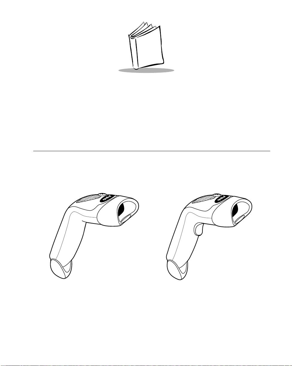
The LS1900 Series scanner combines excellent scanning performance and advanced
ergonomics to provide the best value in a lightweight laser scanner. Whether used as a
hand-held scanner or in hands-free mode in a stand, the LS1900 Series ensures comfort
and ease of use for extended periods of time.
LS1902C “Triggerless”
Figure 1-1. LS1900 Series Scanner
LS1900T/LS1902T “Triggered”
1-1
Page 17

LS1900 Series Product Reference Guide
Note:Unless otherwise noted, the term LS190xx refers to all versions of
the scanner.
Here’s what each member of the LS190xx family offers you:
• LS1902T - This triggered decoded scanner supports the following interfaces:
• Standard RS-232C connection to a host. Proper communications of the
scanner with the host is set up by scanning bar codes.
• Keyboard Wedge connection to a host. Scanned data is interpreted by your
host as keystrokes.
• International Keyboards supported: North America, German, French, French
International, Spanish, Italian, Swedish, British, and Japanese.
• Wand Emulation connection to a host. The scanner is connected to a portable
data terminal, a controller, or host which collects the data as wand data and
interprets it for the host.
• Synapse capability which allows you to connect to a wide variety of host
systems using a Synapse and Synapse adapter cable to connect to a host.
• LS1902C - This ‘triggerless’ decoded scanner offers the same technology and
design as the LS1902T.
• LS1900T - This undecoded version of the LS1902T provides connectivity to
portable terminals and external interface controllers.
Unpacking Your Scanner
Remove the scanner from its packing and inspect it for damage. If the scanner was
damaged in transit, call the Symbol Support Center at one of the telephone numbers listed
on page xi. KEEP THE P ACKING. It is the approved shipping container and should be used
if you ever need to return your equipment for servicing.
1-2
Page 18
Getting Started
Setting Up the LS1900 Series Scanner
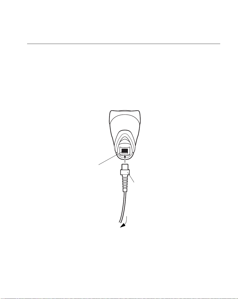
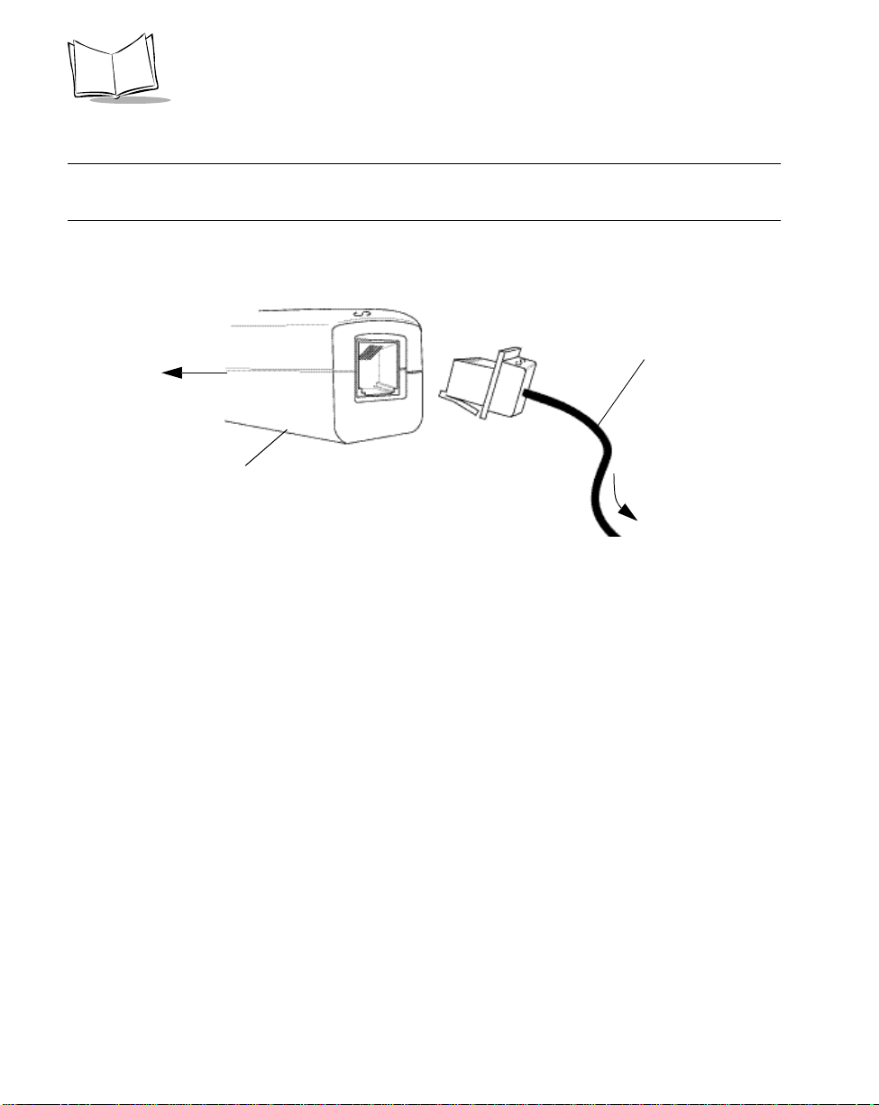
Installing the Interface Cable
1. Plug the interface cable modular connector into the cable interface port on the
bottom of the LS1900 Series handle. (See Figure 1-2.)
2. Gently tug the cable to ensure the connector is properly secured.
3. Connect the other end of the interface cable to the host. (See Connecting to a Host
on page 1-4.)
4. Refer to Parameter Descriptions on page 4-10 for information about programming
your scanner.
Cable interface
port
To host
Figure 1-2. Installing the Cable
Interface cable modular
connector
1-3
Page 19

LS1900 Series Product Reference Guide
Removing the Interface Cable
Different cables are required for different hosts. To remove the interface cable:
1. Unplug the installed cable’s modular connector by depressing the connector clip
with the tip of a screwdriver.
2. Carefully slide out the cable.
3. Follow the steps for Installing the Interface Cable on page 1-3 to connect a new
cable.
Connecting to a Host
The LS1900 Series scanner supports RS-232C, Keyboard Wedge, Wand Emulation, and
Synapse to interface to a host system. This section describes how to set up each of these
connections.
Connecting Power
If your host does not provide power to the scanner, you will need an external power
connection to the scanner:
1. Connect the interface cable to the bottom of the scanner, as described in Installing
the Interface Cable on page 1-3.
2. Connect the other end of the interface cable to the host (refer to your host manual
to locate the correct port).
3. Plug the power supply into the power jack on the interface cable. Plug the other
end of the power supply into an AC outlet.
1-4
Page 20
Getting Started
Connecting an RS-232C Interface
This connection is made either directly from the scanner to the host, or indirectly through a
Synapse adapter cable to the host.
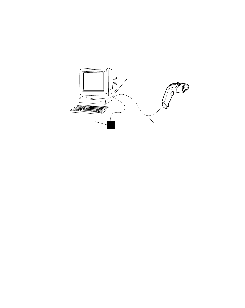
RS-232C Direct Connection
Host serial port
Power supply
Interface cable
Figure 1-3. RS-232C Direct Connection
1. Connect the RS-232C interface cable to the bottom of the scanner, as described in
Installing the Interface Cable on page 1-3.
2. Connect the other end of the interface cable to the serial port on the host.
3. Connect the power supply.
Connecting a Keyboard Wedge Interface
When configured for Keyboard Wedge input, the host accepts input from the scanner as
keystrokes. The LS1900 Series scanner can perform Keyboard Wedge input using a
Keyboard Wedge cable, or a Synapse adapter cable (see Figure 1-6 on page 1-8).
1-5
Page 21

LS1900 Series Product Reference Guide
Keyboard Wedge Cable Connection
Host keyboard port
Y-cable keyboard
connector
Y-cable modular
connector
Power supply
(if needed)
Figure 1-4. Keyboard Wedge Connection with Y-cable
1. Switch off the host and unplug the keyboard connector.
2. Attach the modular connector of the Y-cable to the cable interface port on the
scanner. (See Installing the Interface Cable on page 1-3.)
3. Connect the round male DIN host connector of the Y-cable to the keyboard port on
the host device.
4. Connect the round female DIN keyboard connector of the Y-cable to the keyboard.
5. If needed, attach the optional power supply to the connector in the middle of the Ycable.
6. Ensure that all connections are secure.
7. Switch on your host system. You are now ready to read bar codes.
Note:During sca nni ng , PC- co m pat ib l e h os t t er mi n al s sh ould be in CAPS
LOCK OFF mode.
1-6
Page 22
Getting Started
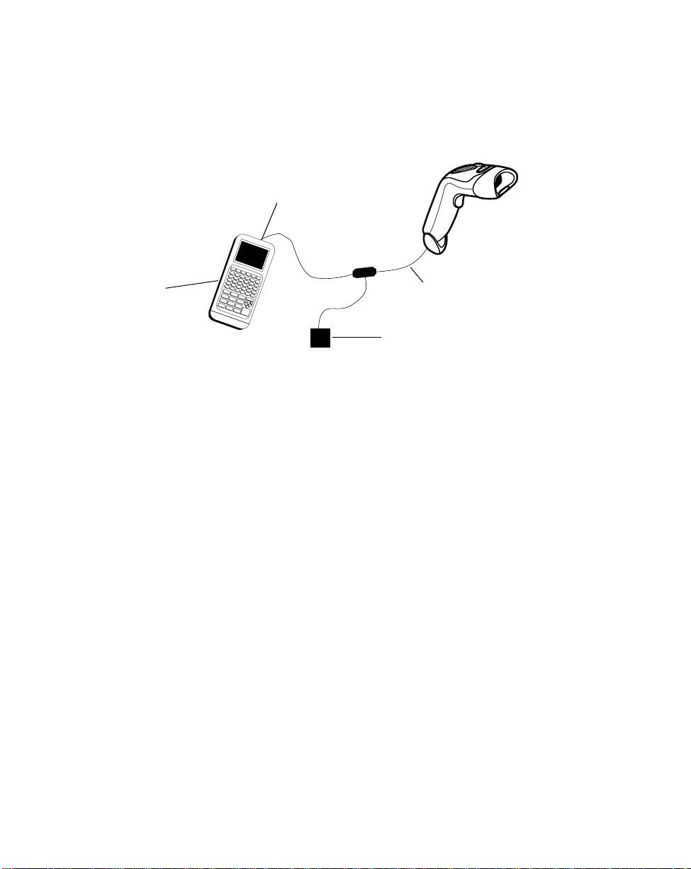
Connecting a Wand Emulation Interface
T o perform Wand Emulation, connect the scanner to a portable data terminal, or a controller
which collects the data as wand data and interprets it for the host.
Portable data terminal COM port
Portable data
Terminal
Interface cable
Power supply
(if needed)
Figure 1-5. Wand Emulation Connection
1. Connect the Wand Emulation interface cable to the bottom of the scanner, as
described in Installing the Interface Cable on page 1-3.
2. Connect the other end of the interface cable to the COM port on the portable data
terminal or controller.
3. Plug one end of the power supply cable into the power receptacle on the interface
cable. Plug the other end of the power supply cable into a wall outlet.
1-7
Page 23
LS1900 Series Product Reference Guide
Connecting a Synapse Cable Interface
Note:See the Synapse Interface Guide provided with your Synapse cable
for detailed setup instructions.
Symbol’s Synapse Smart Cables enable interfacing to a variety of hosts. The appropriate
Synapse cable has the built-in intelligence to detect the host to which it is connected.
To host
Synapse Smart Cable
Synapse adapter cable
To scanner
Figure 1-6. Synapse Cable Connection
1. Plug the Synapse adapter cable (p/n
25-32463-xx)
into the bottom of the scanner,
as described in Installing the Interface Cable on page 1-3.
2. Plug the other end of the adapter cable into the Synapse Smart Cable.
3. Connect the other end of the Synapse Smart Cable to the host.
1-8
Page 24
Chapter 2
Scanning
Introduction
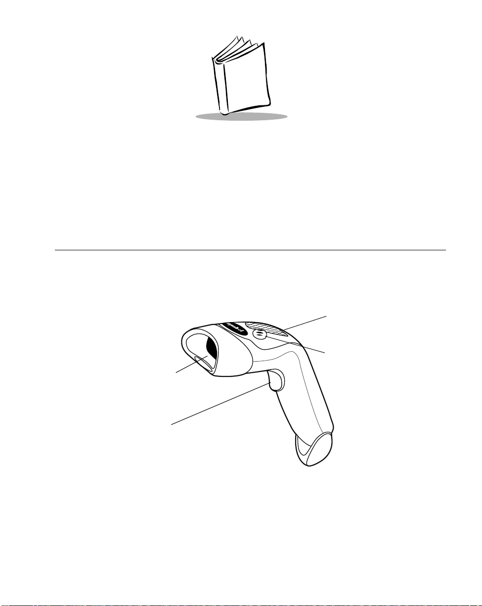
This chapter covers the techniques involved in scanning bar codes, beeper and LED
definitions, and general instructions and tips about scanning.
LED
Beeper
Exit Window
Trigger
(Model LS190xT only)
Figure 2-1. LS1900 Series Scanner Parts
2-1
Page 25

LS1900 Series Product Reference Guide
Beeper Definitions
The scanner communicates with the user by emitting different beep tones and patterns.
Table 2-1 defines beep sequences that occur during both normal scanning and while
programming the scanner.
Table 2-1. Standard Beeper Definitions
Beeper Sequence Indication
Standard Use
Short high tone A bar code symbol was decoded (i f decode beep er
is enabled).
4 Beeps - long low tone A transmission error was detected in a scanned
symbol. The data is ig nored. This occurs i f a unit is
not properly configured. Check option setting.
5 Beeps - low tone Conversion or format error.
Lo/hi/lo tone ADF transmit error.
Hi/hi/hi/lo tone RS-232C receive error.
Parameter Menu Scanning
2-2
Short high tone Correct entry scanned or correct menu sequence
performed.
Lo/hi tone Input error , incorrect bar code or “Cancel” sca nned,
wrong entry, incorrect bar code prog ra mmin g
sequence; remain in program mode.
Hi/lo tone Keyboard parameter selected. Enter value using
bar code keypad.
Hi/lo/hi/lo tone Successful program ex it with change in the
parameter setting.
Code 39 Buffering
Hi/lo tone New Code 39 data was entered into the buffer.
3 Beeps - long high tone Code 39 buffer is full.
Lo/hi/lo tone The buffer was erased, or there was an attempt to
transmit an empty buffer. The Code 39 buffer was
erased or there was an atte mpt to clear or tran smit
an empty buffer.
Page 26

Scanning
Table 2-1. Standard Beeper Definitions (Continued)
Beeper Sequence Indication
4 Beeps - long low tone Error in data transmission.
Lo/hi tone A successful transmission of buffered data.
LED Definitions
In addition to beep tones, the scanner communicates with the user using a two-color LED
display. Table 2-2 defines LED colors that display during scanning.
Table 2-2. Standard LED Definitions
LED Indication
Off No power is applied to the scanner, or the scanner
is on and ready to scan.
Green A bar code was successfully decoded.
Red A data transmission error or scanner malfunction
occurred.
2-3
Page 27
LS1900 Series Product Reference Guide
Scanning in Hand-Held Mode
Install and program your scanner. (Refer to Chapter 4, Programming the Scanner for
instructions on programming your scanner.) If you need assistance, contact your local
supplier or the Symbol Support Center.
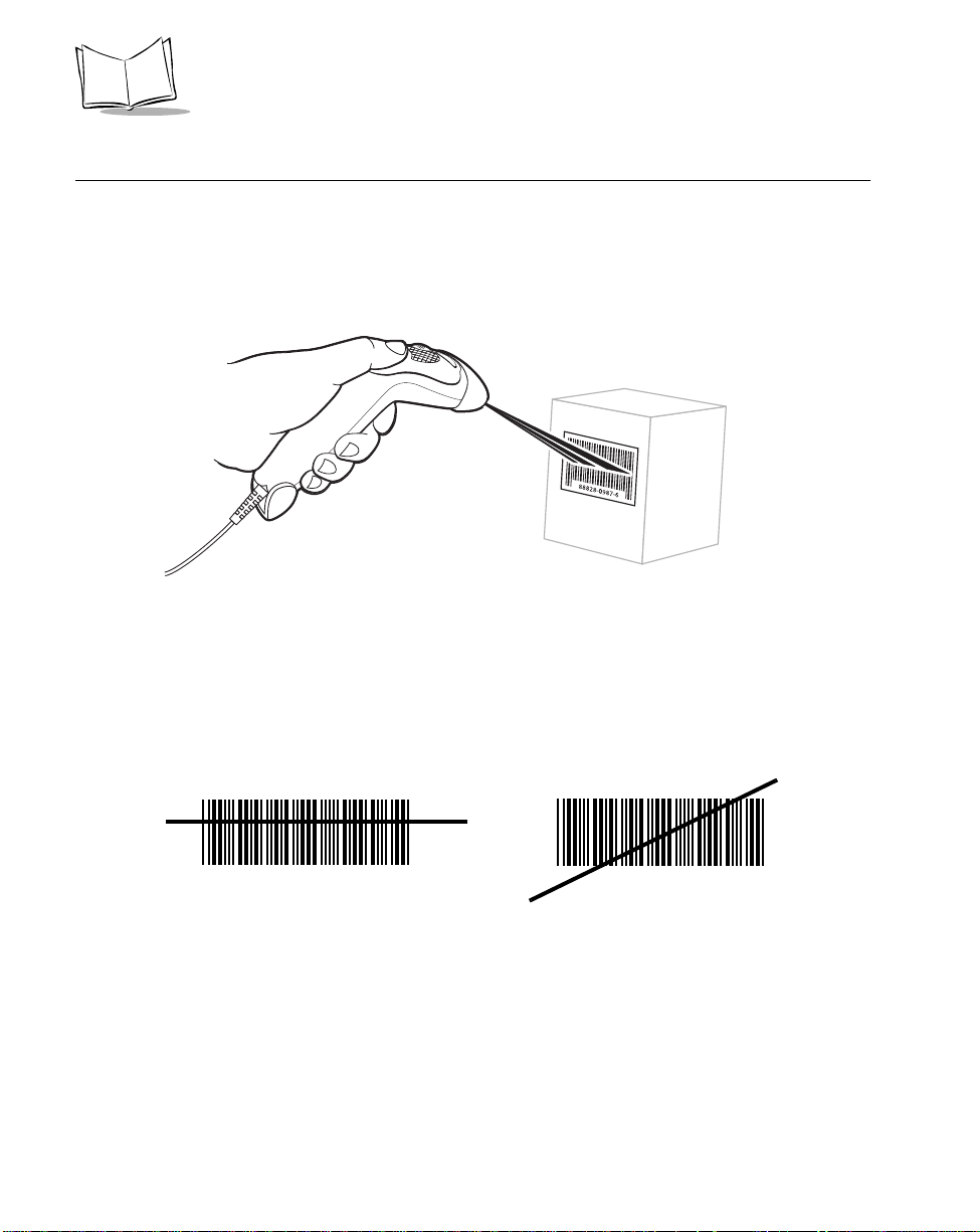
Scanning with the LS190xx
Figure 2-2. Scanning with the LS190xx
1. Ensure all connections are secure. (See Connecting to a Host on page 1-4.)
2. Aim the scanner at the bar code. If your scanner has a trigger, aim and press the
trigger. (See Aiming on page 2-5 and Decode Zones on page 2-6.)
3. Ensure the scan line crosses every bar and space of the symbol.
RIGHT
012345
4. Upon successful decode, the scanner beeps and the LED turns green. (For more
information on beeper and LED definitions, refer to Table 2-1 and Table 2-2.)
2-4
WRONG
012345
Page 28
Scanning
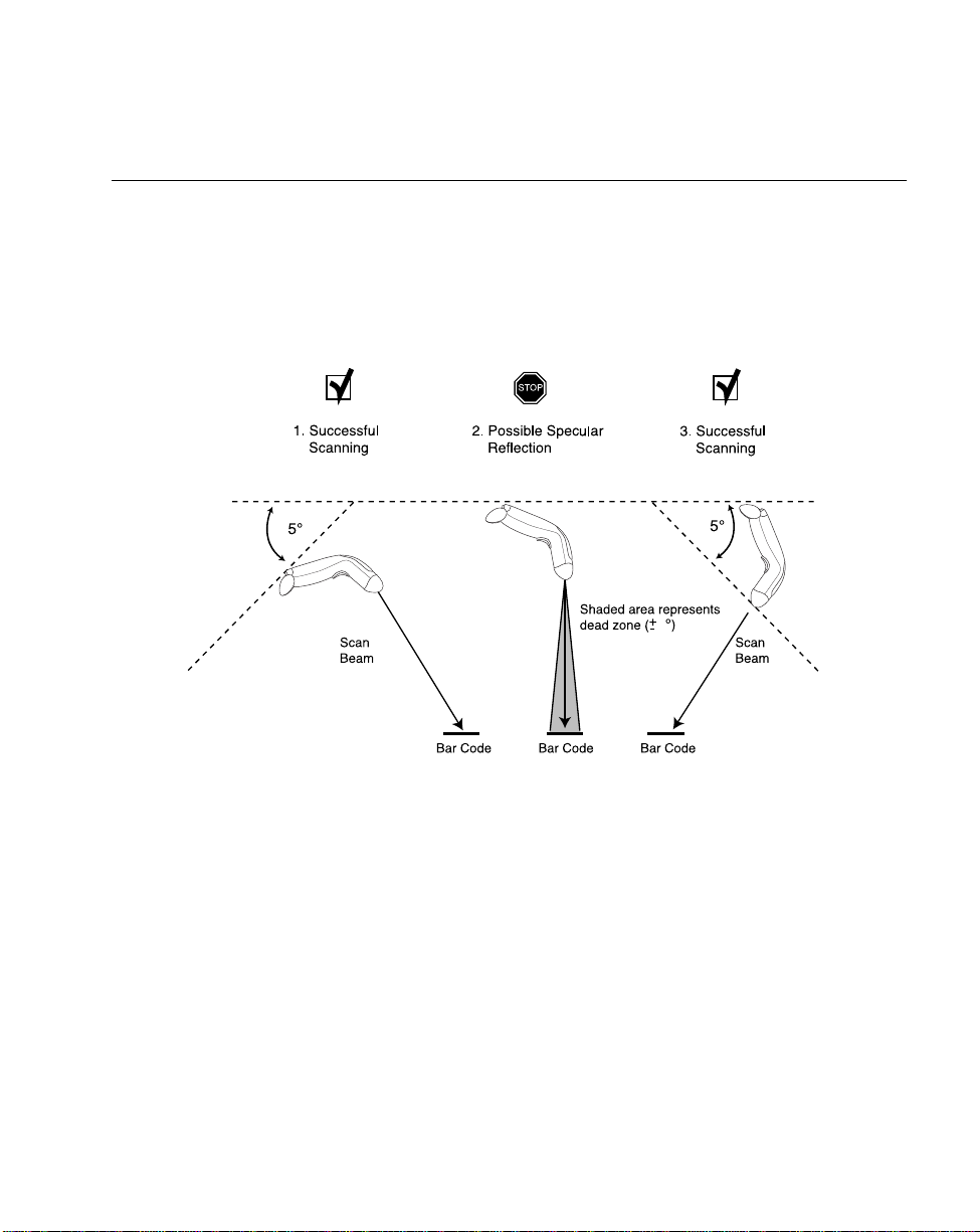
Aiming
Do not hold the scanner directly over the bar code. Laser light reflecting directly back into
the scanner from the bar code is known as specular reflection. This specular reflection can
make decoding difficult. The area where specular reflection occurs is known as a “dead
zone”.
Y ou can tilt the scanner up to 65° forward or back and achieve a successful decode (Figure
2-3). Simple practice quickl y show s what toler anc es to work with in.
6
6
4
Figure 2-3. Maximum Tilt Angles and Dead Zone
2-5
Page 29
LS1900 Series Product Reference Guide
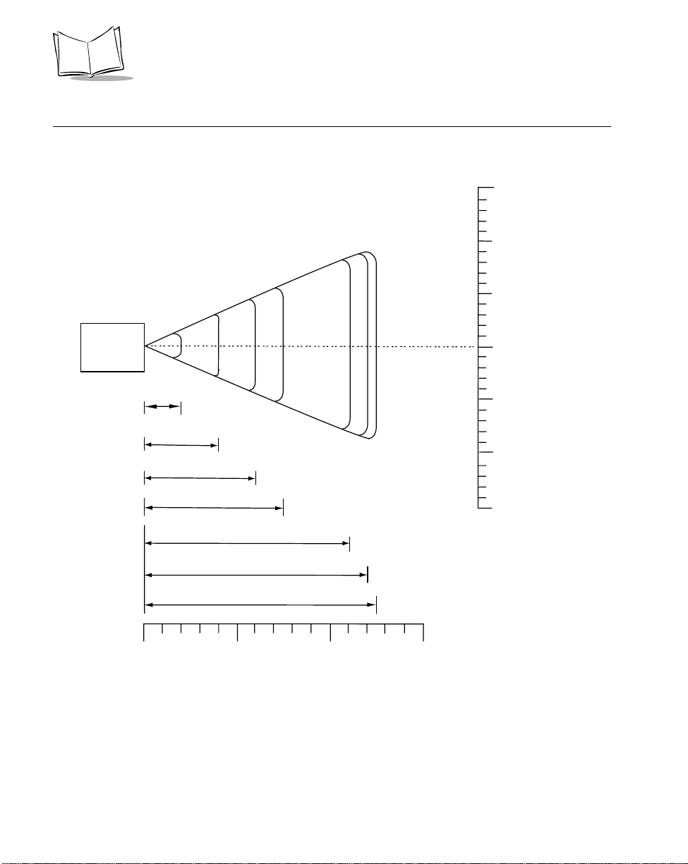
Decode Zones
Note: Typical performance at 73˚ F (23˚ C) on
high quality symbols in normal room light.
LS1902C
5 mil
7.5 mil
2
4
10 mil
6
100% UPC
20 mil
40 mil
0
0
0
0
*
55 mil
7.5
11
12
12.5
in. cm
15
38.1
25.4
10
12.7
5
0
0
5
12.7
10
25.4
15
38.1
W
i
d
t
h
o
f
F
i
e
l
d
2-6
in.
cm
0
0
5
12.7
10
25.4
38.1
Depth of Field
*Minimum distance determined by symbol length and scan angle
Figure 2-4. LS1902C Decode Zone
15
Page 30
Scanning
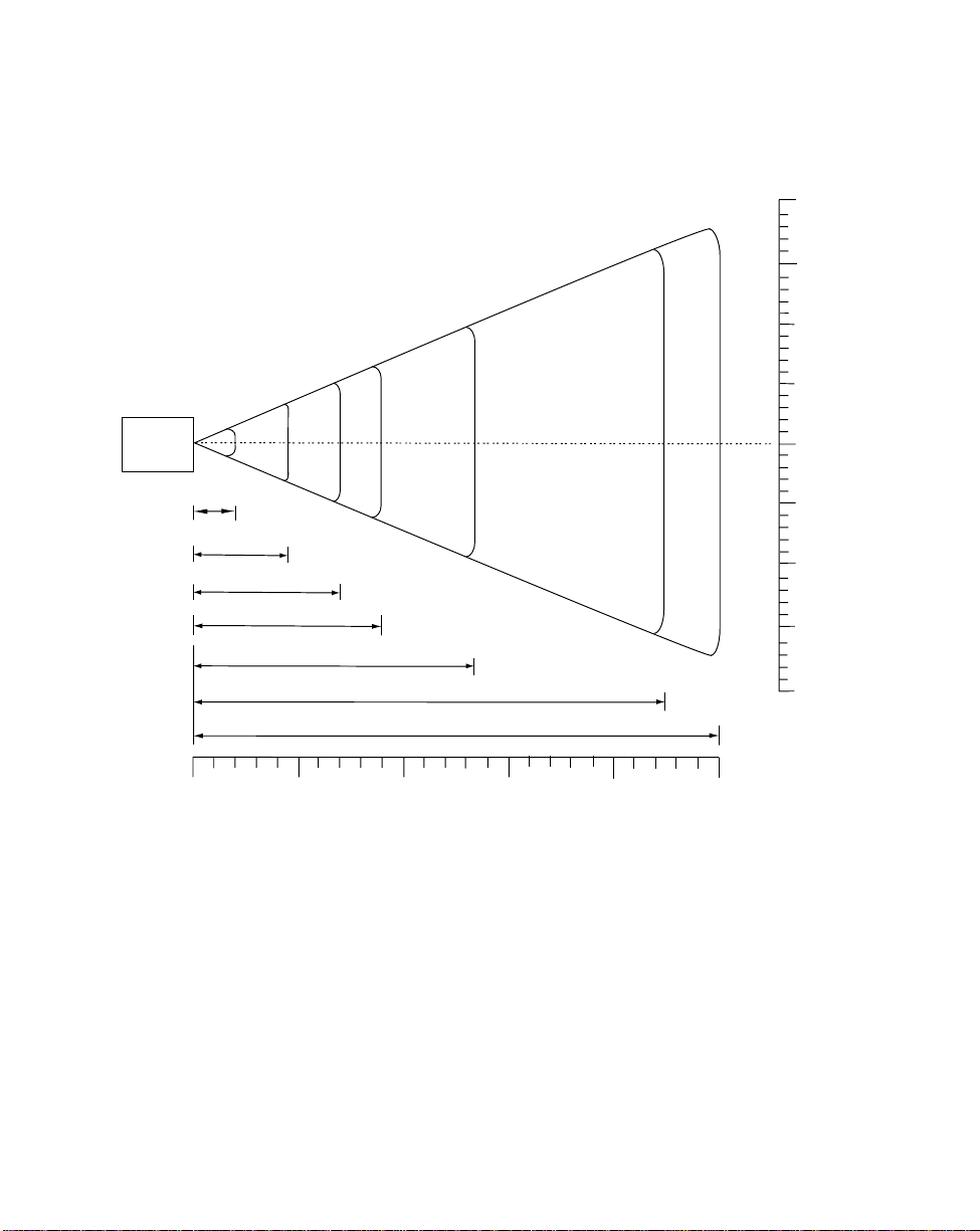
Note: Typical performance at 73˚ F (23˚ C) on
high quality symbols in normal room light.
LS1902T
5 mil
0
0
0
0
2
7.5 mil
10 mil
100% UPC
4.5
7
20 mil
*
in. cm
50.820
38.1
15
25.4
10
W
i
d
5
0
5
0
12.7
h
o
f
F
i
t
12.7
e
l
25.4
38.1
50.820
d
10
9
13.5
40 mil
55 mil
22.5
25
15
in.
cm
0
0
5
12.7
10
25.4
15
38.1
Depth of Field
*Minimum distance determined by symbol length and scan angle
Figure 2-5. LS1900T/LS1902T Decode Zone
20
50.8
25
63.5
2-7
Page 31

LS1900 Series Product Reference Guide
Scanning in Hands-Free Mode
The LS1900 Series Intellistand adds greater flexibility to your scanning operation. Refer to
Assembling the Stand, Mounting the Stand (optional), and S canni ng in the Sta nd for
detailed information about hands-free scanning.
Assembling the Stand
One piece scanner “cup”
with flexible neck.
Tubular neck enclosure
Stand base
1. Unscrew the wingnut
from the bottom of the
one piece scanner “cup”.
2. Insert the neck of the
scanner “cup” into the
tubular neck enclosure.
3. Fit the bottom of the neck
piece into the opening on
the top of the stand base.
4. Tighten the wingnut
underneath the base to
secure the cup and neck
piece to the base.
5. Bend the neck to the
desired position for
scanning.
2-8
Wingnut
Page 32

Scanning
Mounting the Stand (optional)
Y ou can attach the base of the LS190xx scanner’s stand to a flat surface using two screws
or double-sided tape (not provided).
Two screw-mount holes.
Double-sided tape
areas
(3 places)
Figure 2-6. Mounting the Stand
Screw Mount
1. Position the assembled base on a flat surface.
2. Screw one #10 wood screw into each screw-mount hole until the base of the stand
is secure (see Figure 2-6).
Tape Mount
1. Peel the paper liner off one side of each piece of tape and place the sticky surface
over each of the three rectangular tape holders.
2. Peel the paper liner off the exposed sides of each piece of tape and press the stand
on a flat surface until it is secure (see Figure 2-6).
Note:
Mounting the stand is optional.
2-9
Page 33

LS1900 Series Product Reference Guide
Scanning in the Stand
When seated in the stand’s “cup”, the scanner’s built-in sensor places the LS190xx in
constant-on mode. When the scanner is removed from the stand it operates in its normal
hand-held mode (e.g., constant-on mode or trigger mode, depending on the model).
Figure 2-7. Inserting and Using the Scanner in the Stand
1. Ensure all cable connections are secure.
2. Insert the LS190xx scanner in the optional hands-free stand by placing the front of
the scanner into the stand’s “cup” (see Figure 2-7). When not in us e, the s canner’s
laser is in a constant blinking state.
3. To scan a bar code, present the bar code and ensure the scan line crosses every
bar and space of the symbol. (See Aiming on page 2-5 and Decode Zones on page
2-6.)
4. The scan beam becomes steady when the scanner is decoding the bar code.
5. Upon successful decode, the scanner beeps and the LED turns green.
2-10
Page 34

Chapter 3
Maintenance and Technical Specifications
Introduction
This chapter covers the LS1900 Series suggested maintenance, troubleshooting, technical
specifications, and signal descriptions (pinouts).
Maintenance
Cleaning the exit window is the only maintenance required. A dirty window may affect
scanning accuracy.
• Do not allow any abrasive material to touch the window
• Remove any dirt particles with a damp cloth
• Wipe the window using a tissue moistened with ammonia/water
• Do not spray water or other cleaning liquids directly into the window
• Do not remove the rubber nose of the scanner.
3-1
Page 35

LS1900 Series Product Reference Guide
Troubleshooting
Problem Possible Causes Possible Solutions
Nothing happens whe n
you follow the operating
instructions.
Laser comes on, but
symbol does not deco de.
Symbol is decoded, but
not transmitted to the host.
Scanned data is
incorrectly displayed on
the host.
No power to the scanner. Check the system power. Ensure the power
Interface/power ca bles are
loose.
Scanner is not programmed for
the correct bar code type.
Bar code symbol is unreadable. Check the symbol to make sure it is not
Distance between scanner and
bar code is incorrect.
Scanner is not programmed for
the correct host type.
Scanner is not programmed to
work with the host. Check
LS1900 Series host type
parameters or editing options.
Table 3-1. Troubleshooting
supply is connected if your configuration
requires a power supply.
Check for loose cable connections.
Be sure t he scanner i s progra mmed to r ead
the type of bar code you are scanning.
defaced. Try scanning test symb ol s of th e
same bar code type.
Move the scanner close r to or fur t her from
the bar code.
Scan the appropriate ho st ty pe bar code.
Be sure proper host is selected. (See
Chapter 4, Programming the Scann er .)
For RS-232C, ensure th e scanner’s
communication param eters match the
host’s settings.
For a keyboard wedge conf i gur at i on,
ensure the system is programmed for the
correct keyboard type, a nd t he C APS
LOCK key is off .
Be sure editing options (e.g., UPC-E to
UPC-A Conve r sion) are properly
programmed.
Note:If after performing these checks the symbol still does not scan,
contact your distributor or call the Symbol Support Center. See page
xi for the telephone number.
3-2
Page 36

Technical Specifications
T able 3-2. Technical Specifications
ITEM DESCRIPTION
Maintenance and Technical Specifications
Power Requirements
Stand-By Current 1 mA (max)
Decode Capability UPC/EAN, UPC/EAN with supplementals, UCC/EAN
Beeper Operation User-selectable: Enable, Disable
Beeper Volume User-selectable: three levels
Beeper Tone User-selectable: three tones
Decode Depth of Field Refer to LS1902C Decode Zone on page 2-6 and
Scan Repetition Rate Approximately 44 scans/sec. (bidirectional)
Skew Tolerance ± 60° min. (from normal)
Pitch Tolerance ± 65° (from normal)
Roll Tolerance ± 10° (from normal) dependent on bar code height
Print Contrast Minimum 25% minimum r eflectance differentia l, measured at
LS 1902C/T:
4.5 – 5.5 VDC @ 100 mA nominal
LS 1900T:
4.8 – 14 VDC @ 80mA nominal
128, Code 39, Code 39 Full ASCII, Codabar,
Interleaved 2 of 5, Discrete 2 of 5, Code 128, Code
93, MSI/Plessey , Code 1 1, UCC/EAN, RSS, Code 32,
Coupon Code, and Bookland EAN
LS1900T/LS1902T Decode Zone on page 2-7
650 nm.
Ambient Light Immunity
Indoor:
Outdoor:
Durability 5 ft (1.5 m) drops to concrete
Operating Temperature 32° to 104° F (0° to 40° C)
Storage Temperature -40° to 140° F (-40° to 60° C)
Humidity 5% to 95% (non-condensing)
450 Ft Candles (4,842 Lux)
8,000 Ft Candles (86,112 Lux)
3-3
Page 37

LS1900 Series Product Reference Guide
T a ble 3-2. Technical Specifications (Continued)
ITEM DESCRIPTION
Weight (without cable)
Dimensions:
Height
Weight
Depth
Laser Classifications CDRH Class 2 (triggered models)
Minimum Element Width 5 mil (0.127 mm)
LS1902C/T:
4.2 oz. (120 g)
LS1900T:
4.0 oz. (115 g)
5.3 in. (3.4 cm)
2.5 in. (6.4 cm)
2.2 in. (5.7 cm)
IEC Class 1 (triggerless models)
3-4
Page 38

Maintenance and Technical Specifications
LS1900 Series Signal Descriptions
Bottom of scanner
Cable interface port
PIN 10
Interface cable
modular connector
PIN 1
Figure 3-1. LS1900 Series Scanner Cable Pinouts
3-5
Page 39

LS1900 Series Product Reference Guide
The following signal descriptions apply to the connection between the scanner and the
cable, and are for reference only.
Table 3-3. Signal Pin-outs
LS1902
Keyboard
Pin LS1900 Synapse RS-232C
1
Reserved SynClock Reserved Reserved Reserved
2 Power Power Power Power Power
3 Ground Ground Ground Ground Ground
4
Enable Reserved TxD KeyClock DBP
5 SOS Reserved RxD Reserved Reserved
6 Trigger* SynData RTS KeyData RTS
7 Decode Reserved CTS Reserved Reserved
8 DBP Reserved Reserved Reserved Reserved
9 Reserved Reserved Reserved TermData CTS
Wedge Wand
10 Reserved Reserved Reserved TermClock Reserved
3-6
Page 40

Chapter 4
Programming the Scanner
Introduction
You have the option to program the LS1900 Series scanner to perform various functions,
or activate different features. This chapter describes each feature and provides the
programming bar codes necessary for selecting these features for your scanner. Before
programming, follow the instructions in Chapter 1, Getting Started.
Your scanner is shipped with the settings shown in the Default Table on page 4-3. These
default values are stored in non-volatile memory and are preserved even when the scanner
is powered down. If the default values suit your requirements, no programming is
necessary. Features other than default values are set by scanning single bar codes or short
bar code sequences.
Even if the default parameters suit your needs, if you are not using a Synapse cable you
must select a host type. After you hear the power-up beeps, select a host type beginning
on page 4-21. This only needs to be done once, upon the first power-up when connected
to a new host.
To return all features (except Host Type) to their default values, all you need to do is scan
the Set All Defaults bar code on page 4-10. Throughout the programming bar code menus,
default values are indicated with asterisks (
Indicates Default
*
*
).
*
Baud Rate 9600
Feature
4-1
Page 41

LS1900 Series Product Reference Guide
Scanning Sequence Examples
In most cases you need only scan one bar code to set a specific parameter. For example,
if you want to set the baud rate to 19,200, simply scan the 19,200 bar code listed under
Baud Rate on page 4-25. The scanner issues a short high tone and the LED turns green,
signifying a successful parameter entry.
Other parameters, such as specifying Serial Response Time-Out or setting Data
Transmission Formats, require that you scan several bar codes. This procedure is
described later in this chapter.
Errors While Scanning
Unless otherwise specified, if you make an error during a scanning sequence, just re-scan
the correct parameter.
4-2
Page 42

Programming the Scanner
Standard Default Parameters
The following table lists the defaults for all parameters. If you wish to change any option,
scan the appropriate bar code(s) provided in the Parameter Descriptions section beginning
on page 4-10.
Table 4-1. Default Table
Parameter Default Page
Number
Scanner Preferences
Set Default Parameter All Defaults 4-10
Trigger Mode Trigger Mode 4-11
Beeper Tone High 4-12
Beeper Vol ume High 4-13
Laser On Time 3.0 Sec 4-14
Power Mode Low Power 4-15
Beep After Good Decode Enable 4-16
Transmit “No Read” Message Disable 4-17
Linear Code Security Levels 1 4-18
Bi-directional Redundancy Disable 4-20
Host Selection
Select Default Host Type No Host See Host
Types
Host Ty pes
RS-232C Standard 4-23
Keyboard Wedge IBM-A T 4-36
4-3
Page 43

LS1900 Series Product Reference Guide
Table 4-1. Default Table (Continued)
Parameter Default Page
Wand Standard 4-46
RS-232C Parameters
RS-232C Host Types Standard 4-23
Baud Rate 9600 4-26
Parity Ty pe None 4-28
Check Receive Errors Disable 4-28
Hardware Handshaking None 4-30
Software Handshaking None 4-31
Host Serial Response Time-out 2.0 Sec 4-33
RTS Line State Low RTS 4-34
Number
Stop Bit Select 1 4-34
ASCII Format 8-Bit 4-35
Beep on <BEL> Disable 4-35
Keyboard Wedge Parameters
Keyboard Wedge Host Type IBM-AT 4-36
Country Selection American 4-38
Unknown Characters Disable 4-41
Intercharacter Delay 0 msec 4-42
Emulate Keypad Disable 4-43
Send Make Break Disable 4-43
4-4
Page 44

Programming the Scanner
Table 4-1. Default Table (Continued)
Parameter Default Page
Caps Lock Disable 4-44
Caps Cancel Disable 4-44
Alternate Numeric Keypad Emulation Disable 4-45
Wand Emulation Parameters
Wand Emulation Host Types Standard (Symbol) 4-46
Leading Margin 80 msec 4-47
Polarity Bar High/Margin Low 4-48
Ignore Unknown Characters Enable 4-48
Convert to Code 39 Disable 4-49
Code 39 Full ASCII Conversion Disable 4-49
Number
UPC/EAN
UPC-A Enable 4-50
UPC-E Enable 4-50
UPC-E1 Disable 4-50
EAN-8 Enable 4-51
EAN-13 Enable 4-51
Bookland EAN Disable 4-52
Decode UPC/EAN Supplementals (2 and 5 digits) Ignore 4-53
Decode UPC/EAN Supplemental Redundancy 7 4-54
Transmit U PC- A Check D igi t Enable 4-55
4-5
Page 45

LS1900 Series Product Reference Guide
Table 4-1. Default Table (Continued)
Parameter Default Page
Transmit UPC-E Check Digit Enable 4-55
Transmit UPC-E1 Check Digit Enable 4-55
UPC-A Preamble Sy stem Character 4-56
UPC-E Preamble Sy stem Character 4-57
UPC-E1 Preamble System Character 4-58
Convert UPC-E to A Disable 4-59
Convert UPC-E1 to A Disable 4-60
EAN-8 Zero Extend Disable 4-61
Convert EAN-8 to EAN-13 Type Type is EAN-13 4-62
UPC/EAN Security Levels 0 4-63
Number
UPC/EAN Coupon Code Disable 4-65
Random Weight C heck Digit None 4-66
Linear Supplementals Disable 4-67
Code 128
Code 128 Enable 4-68
UCC/EAN-128 Enable 4-69
ISBT 128 Enable 4-70
Code 39
Code 39 Enable 4-71
Trioptic Code 39 Disable 4-72
4-6
Page 46

Programming the Scanner
Table 4-1. Default Table (Continued)
Parameter Default Page
Convert Code 39 to Code 32 Disable 4-73
Code 32 Prefix Disable 4-74
Set Length(s) for Code 39 2 to 55 4-75
Code 39 Check Digit Verification Disable 4-77
Transmit C ode 39 Check Di gi t Disable 4-78
Code 39 Full ASCII Conversion Disable 4-79
Buffer Code 39 Disable 4-80
Code 93
Code 93 Disable 4-83
Set Length(s) for Code 93 4 to 55 4-84
Number
Code 11
Code 11 Disable 4-86
Set Lengths for Code 11 4 to 55 4-87
Code 11 Check Digit Verification 0 4-89
Transmit Code 11 Check Digit Disable 4-90
Interleaved 2 of 5 (ITF)
Interleaved 2 of 5 (ITF) Enable 4-91
Set Length(s) for I 2 of 5 14 4-92
I 2 of 5 Check Digit Verification Disable 4-94
Transmit I 2 of 5 Check Digit Disable 4-95
4-7
Page 47

LS1900 Series Product Reference Guide
Table 4-1. Default Table (Continued)
Parameter Default Page
Number
Convert I 2 of 5 to EAN 13 Disable 4-96
Discrete 2 of 5 (DTF)
Discrete 2 of 5 Disable 4-97
Set Length(s) for D 2 of 5 12 4-98
Codabar
Codabar Disable 4-100
Set Lengths for Codabar 5 to 55 4-102
CLSI Editing Disable 4-103
NOTIS Editing Disable 4-104
MSI Plessey
MSI Plessey Disable 4-105
Set Length(s) for MSI Plessey 1 to 55 4-107
MSI Plessey Check Digits One 4-108
Transmit MSI Ples se y Ch ec k Di gi t Disable 4-109
MSI Plessey Check Digit Algorithm Mod 10/Mod 10 4-110
RSS 14
RSS 14 Disable 4-111
RSS Limited Disable 4-112
RSS Expanded Disable 4-112
Data Options
4-8
Page 48

Programming the Scanner
Table 4-1. Default Table (Continued)
Parameter Default Page
Number
Transmit Code ID Character None 4-113
Intercharacter Delay 0 Sec 4-114
Pause Duration 0 Sec 4-115
Prefix V alue 7013 <CR><LF> 4-116
Suffix Value 7013 <CR><LF> 4-116
Scan Data Options Data as is 4-117
4-9
Page 49

LS1900 Series Product Reference Guide
Parameter Descriptions
Set Default Parameter
Scanning this bar code returns all parameters to the default values listed in Table 4-1 on
page 4-3.
Set All Defaults
4-10
Page 50

Programming the Scanner
Trigger Mode
This parameter is for “triggered” models only. Scan the Triggerless Mode bar code to
turn off trigger functionality and place the scanner in constant on mode. Scan the Trigger
Mode bar code to activate the trigger and turn off constant on mode.
*
Trigger Mode
Triggerless Mode
4-11
Page 51

LS1900 Series Product Reference Guide
Beeper Tone
To select a decode beep frequency (tone), scan the LOW FREQUENCY, MEDIUM
FREQUENCY, or HIGH FREQUENCY bar code.
Low Frequency
Medium Frequency
4-12
*
High Frequency
Page 52

Programming the Scanner
Beeper Volume
To select a beeper volume, scan the LOW VOLUME, MEDIUM VOLUME, or HIGH
VOLUME bar code.
Low Volume
Medium Volume
*
High Volume
4-13
Page 53

LS1900 Series Product Reference Guide
Laser On Time
This parameter sets the maximum time that decode processing continues during a scan
attempt. It is programmable in 0.1 second increments from 0.5 to 9.9 seconds. The default
Laser On Time is 3.0 seconds.
To set a Laser On Time, scan the bar code below. Next scan two numeric bar codes
beginning on 4-119 that correspond to the desired time on. Single digit numbers must have
a leading zero. For example, to set an On Time of .5 seconds, scan the bar code below,
then scan the “0” and “5” bar codes. If you make an error, or wish to change your selection,
scan CANCEL on page 4-121.
4-14
Laser On Time
Page 54

Programming the Scanner
Power Mode
This parameter determines whether or not power remains on after a decode attempt. When
in low power mode, the scanner enters into a low power consumption mode to preserve
battery life after each decode attempt. When in continuous power mode, power remains
on after each decode attempt. Use low power mode when drawing power from a battery
powered device, such as a portable terminal.
Continuous On
*
Low Power
4-15
Page 55

LS1900 Series Product Reference Guide
Beep After Good Decode
Scan a bar code below to select whether or not the unit beeps after a good decode. If DO
NOT BEEP is selected, the beeper still operates during parameter menu scanning and
indicates error condi tio n s.
*
Beep After Good Decode
(Enable)
4-16
Do Not Beep After Good Decode
(Disable)
Page 56

Programming the Scanner
Transmit “No Read” Message
Scan a bar code below to select whether or not a “No Read” message is transmitted. When
enabled, the characters NR are transmitted when a bar code is not decoded. Any prefixes
or suffixes which are enabled are appended around this message. When disabled, if a
symbol does not decode, nothing is sent to the host.
Enable No Read
*
Disable No Read
4-17
Page 57

LS1900 Series Product Reference Guide
Linear Code Type Security Level
The LS1900 Series scanner offers four user selectable levels of decode security for linear
code types (e.g., Code 39, Interleaved 2 of 5). Higher security levels are selected for
decreasing levels of bar code quality. As security levels increase, the scanner’s decode
speed may decrease. Select the security level appropriate for your bar code quality.
Note:
This does not apply to Code 128.
Linear Security Level 1
The following code types must be successfully read twice before being decoded:
Table 4-1.
Code Type Length
Codabar All
MSI Plessey 4 or less
D 2 of 5 8 or less
I 2 of 5 8 or less
*
Linear Security Lev el 1
Linear Security Level 2
All code types must be successfully read twice before being decoded.
Linear Security Level 2
4-18
Page 58

Programming the Scanner
Linear Security Level 3
Code types other than the following must be successfully read twice before being decoded.
The following codes must be read three times:
Table 4-1.
Code Type Length
MSI Plessey 4 or less
D 2 of 5 8 or less
I 2 of 5 8 or less
Codabar 8 or less
Linear Security Level 3
Linear Security Level 4
All code types must be successfully read three times before being decoded.
Linear Security Level 4
4-19
Page 59

LS1900 Series Product Reference Guide
Bi-directional Redundancy
This parameter is only valid when a Linear Code Type Security Level (see page 4-18) is
enabled. When this parameter is enabled, a bar code must be successfully scanned in both
directions (forward and reverse) before being decoded.
Enable Bi-directional Redundancy
4-20
*
Disable Bi-directional Redundancy
Page 60

Programming the Scanner
Host Types
If you are using a Synapse cable, Synapse auto-detects your host so no host bar codes
need to be scanned. If you are not using a Synapse cable you must select a host type in
either the RS-232C, Keyboard Wedge, or Wand Emulation section.
RS-232C Parameters
Five RS-232C hosts are set up with their own parameter default settings (Table 4-2).
Selecting the ICL, Fujitsu, Nixdorf Mode A, or Nixdorf Mode B terminal sets the defaults
listed below. These defaults take precedence over standard defaults and remain selected
if the Set Defaults bar code is scanned.
T a ble 4-2. Terminal Specific RS-232C
Parameter Standard
(Default)
Transmit Code ID No Yes Yes Yes Yes
Data Transmission Format Data as is Data/Suffix Data/Suffix Data/Suffix Data/Suffix
Suffix CR/LF (7013) CR (1013) CR (1013) CR (1013) CR (1013)
Baud Rate 9600 9600 9600 9600 9600
Parity None Even None Odd Odd
Hardware Handshaking None RTS/CTS
Software Handshaking None None None None None
Serial Response Time-out 2 Sec. 9.9 Sec. 2 Sec. 9.9 Sec. 9.9 Sec.
Stop Bit Select One One One One One
ASCII Format 8-Bit 8-Bit 8-Bit 8-Bit 8-Bit
Beep On <BEL> Disable Disable Disable Disable Disable
RTS Line State Low High Low Low Low = No data to
ICL FUJITSU NIXDORF
Option 3
None RTS/CTS
Mode A
Option 3
NIXDORF
Mode B
RTS/CTS
Option 3
send
4-21
Page 61

LS1900 Series Product Reference Guide
RS-232C Host Parameters (co n tinued)
Selecting the ICL, Fujitsu, Nixdorf Mode A, or Nixdorf Mode B terminal enables the
transmission of code ID characters as listed in Table 4-3 below. These code ID characters
are not programmable and are separate from the Transmit Code ID feature. The Transmit
Code ID feature should not be enabled for these terminals.
Table 4-3. Terminal Specific Code ID Characters
ICL FUJITSU NIXDORF
Mode A
UPC-A A A A0 A0
UPC-E EEC0C0
EAN-8 FF FF B B
EAN-13 FFAA
Code 39 C <len> None M M
Codabar N <len> None N N
Code 128 L <len> None K K
I 2 of 5 I <len> None I I
Code 93 None None L L
D 2 of 5 H <len> None H H
UCC/EAN 128 L <len> None P P
MSI/Plessey None None O O
Bookland EAN FFAA
Trioptic None None None None
Code 11 None None None None
RSS 14 None None None None
RSS Limited None None None None
RSS Expanded None None None None
NIXDORF
Mode B
4-22
Page 62

Programming the Scanner
RS-232C Host Interfaces
To select an RS-232C host interface, scan one of the following bar codes.
*
Standard RS-232C
ICL RS-232C
Nixdorf RS-232C Mode A
Nixdorf RS-232C Mode B
4-23
Page 63

LS1900 Series Product Reference Guide
RS-232C Host Interfaces (continued)
Fujitsu RS-232C
OPOS
4-24
Page 64

Programming the Scanner
Baud Rate
Baud rate is the number of bits of data transmitted per second. The scanner's baud rate
setting should match the data rate setting of the host device. If not, data may not reach the
host device or may reach it in distorted form.
Baud Rate 1200
Baud Rate 2400
Baud Rate 4800
4-25
Page 65

LS1900 Series Product Reference Guide
Baud Rate (continued)
*
Baud Rate 9600
Baud Rate 19,200
4-26
Baud Rate 38,400
Page 66

Programming the Scanner
Parity
A parity check bit is the most significant bit of each ASCII coded character. Select the parity
type according to host device requirements.
If you select ODD parity , the parity bit has a value 0 or 1, based on data, to ensure than an
odd number of 1 bits are contained in the coded character.
Odd
If you select EVEN parity, the parity bit has a value 0 or 1, based on data, to ensure than
an even number of 1 bits are contained in the coded character.
Even
Select MARK parity and the parity bit is always 1.
Mark
4-27
Page 67

LS1900 Series Product Reference Guide
Parity (continued)
Select SPACE parity and the parity bit is always 0.
Space
If no parity is required, select NONE.
*
None
Check Receive Errors
Select whether or not the parity, framing, and overrun of received characters are checked.
The type of parity used is selectable through the PARITY par am eter.
Check For Received Errors
*
Do Not Check For Received Errors
4-28
Page 68

Programming the Scanner
Hardware Handshaking
The data interface consists of an RS-232C port designed to operate either with or without
the hardware handshaking lines, Request to Send (RTS), and Clear to Send (CTS).
If Standard RTS/CTS handshaking is not selected, scan data is transmitted as it becomes
available. If Standard RTS/CTS handshaking is selected, scan data is transmitted
according to the following seque nc e:
• The controller reads the CTS line for activity. If CTS is asserted, the controller waits
up to 2 seconds for the host to negate the CTS line. If, after 2 seconds (default),
the CTS line is still asserted, the scanner sounds a transmit error, and any scanned
data is lost.
• When the CTS line is negated, the controller asserts the RTS line and waits up to
2 seconds for the host to assert CTS. When the host asserts CTS, data is
transmitted. If, after 2 seconds (default), the CTS line is not asserted, the scanner
sounds a transmit error, and discards the data.
• When data transmission is complete, the controller negates RTS 10 msec after
sending the last character.
• The host should respond by negating CTS. The controller checks for a negated
CTS upon the next transmission of data.
During the transmission of data, the CTS line should be asserted. If CTS is deasserted for
more than 50 ms between characters, the transmission is aborted, the scanner sounds a
transmission error, and the data is discarded.
If the above communications sequence fails, the scanner issues an error indication. In this
case, the data is lost and must be rescanned.
If Hardware Handshaking and Software Handshaking are both enabled, Hardware
Handshaking takes precedence.
Note:
The DTR signal is jumpered to the active state.
4-29
Page 69

LS1900 Series Product Reference Guide
None
Scan the bar code below if no Hardware Handshaking is desired.
*
None
Standard RTS/CTS
Scan the bar code below to select Standard RTS/CTS Hardware Handshaking.
Standard RTS/CTS
RTS/CTS Option 1
When RTS/CTS Option 1 is selected, the scanner asserts RTS before transmitting and
ignores the state of CTS. The scanner deasserts RTS when the transmission is complete.
RTS/CTS Option 1
RTS/CTS Option 2
When Option 2 is selected, RTS is always high or low (user-programmed logic level).
However, the scanner waits for CTS to be asserted before transmitting data. If CTS is not
asserted within 2 seconds (default), the scanner issues an error indication and discards the
data.
RTS/CTS Option 2
4-30
Page 70

Programming the Scanner
RTS/CTS Option 3
When Option 3 is selected, the scanner asserts RTS prior to any data transmission,
regardless of the state of CTS. The scanner waits up to 2 seconds (default) for CTS to be
asserted. If CTS is not asserted during this time, the scanner issues an error indication and
discards the data. The scanner deasserts RTS when transmission is complete.
RTS/CTS Option 3
Software Handshaking
This parameter offers control of the data transmission process in addition to, or instead of,
that offered by hardware handshaking. There are five options.
If Software Handshaking and Hardware Handshaking are both enabled, Hardware
Handshaking takes precedence.
None
When this option is selected, data is transmitted immediately.
*
None
4-31
Page 71

LS1900 Series Product Reference Guide
ACK/NAK
When this option is selected, after transmitting data, the scanner expects either an ACK or
NAK response from the host. When a NAK is received, the scanner transmits the same
data again and waits for either an ACK or NAK. After three unsuccessful attempts to send
data when NAKs are received, the scanner issues an error indication and discards the data.
The scanner waits up to the programmable Host Serial Response Time-out to receive an
ACK or NAK. If the scanner does not get a response in this time, it issues an error indication
and discards the data. There are no retries when a time-out occurs.
ACK/NAK
ENQ
When this option is selected, the scanner waits for an ENQ character from the host before
transmitting data. If an ENQ is not received within 2 seconds, the scanner issues an error
indication and discards the data. The host must transmit an ENQ character at least every
2 seconds to prevent transmission errors.
ACK/NAK with ENQ
This combines the two previous options.
ACK/NAK with ENQ
4-32
ENQ
Page 72

Programming the Scanner
XON/XOFF
An XOFF character turns the scanner transmission off until the scanner receives an XON
character. There are two situations for XON/XOFF:
• XOFF is received before the scanner has data to send. When the scanner has data
to send, it waits up to 2 seconds for an XON character before transmission. If the
XON is not received within this time, the scanner issues an error indication and
discards the data.
• XOFF is received during a transmission. Data transmission then stops after
sending the current byte. When the scanner receives an XON character, it sends
the rest of the data message. The scanner waits indefinitely for the XON.
XON/XOFF
Host Serial Response Time-out
This parameter specifies how long the scanner waits for an ACK, NAK, or CTS before
determining that a transmission error has occurred. This only applies when in one of the
ACK/NAK Software Handshaking modes, or RTS/CTS Hardware Handshaking option.
The delay period can range from 0.0 to 9.9 seconds in .1-second increments. After
scanning the bar code below, scan two numeric bar codes beginning on page 4- 119. If
you make an error or wish to change your selection, scan CANCEL on page 4-121.
Host Serial Response Time-out
4-33
Page 73

LS1900 Series Product Reference Guide
RTS Line State
This parameter sets the idle state of the Serial Host RTS line. Scan a bar code below to
select LOW RTS or HIGH RTS line state.
*
Host: Low RTS
Host: High RTS
Stop Bit Select
The stop bit(s) at the end of each transmitted character marks the end of transmission of
one character and prepares the receiving device for the next character in the serial data
stream. The number of stop bits selected (one or two) depends on the number the receiving
terminal is programmed to accommodate. Set the number of stop bits to match host device
requirements.
4-34
*
1 Stop Bit
2 Stop Bits
Page 74

Programming the Scanner
ASCII Format
This parameter allows the scanner to interface with devices requiring a 7-bit or 8-bit ASCII
protocol.
7-Bit
*
8-Bit
Beep on <BEL>
When this parameter is enabled, the scanner issues a beep when a <BEL> character is
detected on the RS-232C serial line. <BEL> is issued to gain a user's attention to indicate
an illegal entry or other important event.
Beep On <BEL> Character
(Enable)
*
Do Not Beep On <BEL> Character
(Disable)
4-35
Page 75

LS1900 Series Product Reference Guide
Keyboard Wedge Parameters
Keyboard Wedge Host Interfaces
Scan the appropriate bar code below to select your host interface.
IBM PS/2
4-36
*
IBM AT
IBM AT NOTEBOOK
Page 76

Keyboard Wedge Host Interfaces (conti nued)
IBM XT
Programming the Scanner
NCR 7052
4-37
Page 77

LS1900 Series Product Reference Guide
Country Selection
Scan the appropriate bar code below to select the corresponding national keyboard type.
*
American
German
4-38
French
Page 78

Country Selection (continued)
Programming the Scanner
French International
Spanish
Italian
Swedish
4-39
Page 79

LS1900 Series Product Reference Guide
Country Selection (continued)
British
Japanese
4-40
Page 80

Programming the Scanner
Unknown Characters
When enabled, all data is sent except for unknown characters, and no error beeps are
sounded. Unknown characters are those characters the selected terminal does not recognize. When disabled, bar codes with unknown characters are decoded, but not transmitted
to the host. A decode beep is followed by a communications error beep indication.
Send Unknown Characters
(Enable)
*
Do Not Send Unknown Characters
(Disable)
4-41
Page 81

LS1900 Series Product Reference Guide
Intercharacter Delay
Increasing the intercharacter delay gives the host system time to service its receiver and
perform other tasks between characters.
Short (5 MS) Delay
Medium (50 MS) Delay
Long (99 MS) Delay
For systems that can handle faster character transmission, scan the NO DELA Y bar code
below.
*
No Delay
4-42
Page 82

Programming the Scanner
Emulate Keypad
When enabled, all characters are sent as ASCII sequences over the numeric keypad. For
example, ASCII A would be sent as “ALT make” 0 6 5 “ALT Break”.
Enable Emulate Keypad
*
Disable Emulate Keypad
Send Make Break
When enabled, the scan codes for releasing a key are not sent.
Enable Send Make Break
*
Disable Send Make Break
4-43
Page 83

LS1900 Series Product Reference Guide
Caps Lock
When enabled, the keyboard acts as if the Caps Lock key is always pressed.
Enable Caps Lock On
*
Disable Caps Lock On
Caps Cancel
When enabled, on AT or AT Notebook machines, the keyboard ignores the state of the
Caps Lock key. Therefore, an ‘A’ in the bar code is sent as an ‘A’ no matter what the state
of the keyboard’s Caps Lock key.
4-44
Enable Caps Off
*
Disable Cap s Off
Page 84

Programming the Scanner
Alternate Numeric Keypad Emulation
When enabled, it translates a normal keyboard character into its Alt-numeric keypad
equivalent. This only works for AT, AT Notebook, or PS/2 machines.
Enable Alt ernate Numeric Keypad Emulation
*
Disable Alternate Numeric Keypad Emulat ion
4-45
Page 85

LS1900 Series Product Reference Guide
Wand Emulation Parameters
Wand Emulation Host Interfaces
Scan the appropriate bar code below to select your host interface.
*
Symbol
MSI
4-46
Telxon
Norand
Page 86

Programming the Scanner
Leading Margin
Scan a bar code below to select a leading margin. A leading margin is the length of leading
space data that precedes the first bar of scan data in milliseconds. The minimum allowed
value is 80 msec and the maximum is 250 msec. A value of 0 is the default and is
interpreted as 80 msec.
*
80 msec
140 msec
200 msec
4-47
Page 87

LS1900 Series Product Reference Guide
Polarity
Scan the appropriate bar code below to select polarity.
*
Bar High/Margin Low
Bar Low/Margin High
Unknown Characters
When enabled, all data is sent except for unknown characters, and no error beeps are
sounded. Unknown characters are those characters the selected terminal does not recognize. When disabled, bar codes with unknown characters are decoded, but not transmitted
to the host. A decode beep is followed by a communications error beep indication.
4-48
Send Unknown Characters
*
Do Not Send Unknown Characters
Page 88

Programming the Scanner
Convert to Code 39
Scan the appropriate bar code below to enable or disable the conversion of all bar code
data to Code 39.
Enable Convert to Code 39
*
Disable Convert to Code 39
Code 39 Full ASCII Conversion
Scan the appropriate bar code below to enable or disable the conversion of all bar code
data to Code 39 full ASCII data.
Enable Code 39 Full ASCII Conversion
*
Disable Code 39 Full ASCII Conversion
4-49
Page 89

LS1900 Series Product Reference Guide
Enable/Disable UPC-E/UPC-A/UPC-E1
To enable or disable UPC-E, UPC-A or UPC-E1, scan the appropriate bar code below.
*
Enable UPC-E
Disable UPC-E
*
Enable UPC-A
4-50
Disable UPC-A
Enable UPC-E1
*
Disable UPC-E1
Page 90

Programming the Scanner
Enable/Disable EAN-8/EAN-13
To enable or disable EAN-8 or EAN-13, scan the appropriate bar code below.
*
Enable EAN-8
Disable EAN-8
*
Enable EAN-13
Disable EAN-13
4-51
Page 91

LS1900 Series Product Reference Guide
Enable/Disable Book l an d EAN
To enable or disable Bookland EAN, scan the appropriate bar code below.
Enable Bookland EAN
*
Disable Bookland EAN
4-52
Page 92

Programming the Scanner
Decode UPC/EAN Supplementals
Supplementals are additionally appended characters (2 or 5) according to specific code
format conventions (e.g., UPC A+2, UPC E+2, EAN 8+2). Three options are available.
• If UPC/EAN with supplemental characters is selected, UPC/EAN symbols without
supplemental characters are not decoded.
• If UPC /EA N w ith ou t su pp lem en tal ch ara ct er s is sel ec ted , a nd t he LS1900
Series scanner is presented with a UPC/EAN plus supplemental symbol, the
UPC/EAN is decoded and the supplemental characters ignored.
• An autodiscriminate option is also available. If this option is selected, choose an
appropriate Decode UPC/EAN Supplemental Redundancy value from the next
page. A value of 5 or more is recommended.
Note:In order to minimize the risk of invalid data transmission, it is
recommended that you select either to decode or ignore
supplemental characters.
Decode UPC/EAN With Supplementals
*
Ignore UPC/EAN With Supplementals
Autodiscriminate UPC/EAN Supplementals
4-53
Page 93

LS1900 Series Product Reference Guide
Decode UPC/EAN Supplemental Redundancy
With Autodiscriminate UPC/EAN Supplementals selected, this option adjusts the number
of times a symbol without supplementals is decoded before transmission. The range is from
two to twenty times. Five or above is recommended when decoding a mix of UPC/EAN
symbols with and without supplementals, and the autodiscriminate option is selected.
Scan the bar code below to select a decode redundancy value. Next scan two numeric bar
codes beginning on page 4-119. Single digit numbers must have a leading zero. If you
make an error, or wish to change your selection, scan CANCEL on page 4-121.
Decode UPC/EAN
Supplemental Redundancy
4-54
Page 94

Programming the Scanner
Transmit UPC-A/UPC-E/UPC-E1 Check Digit
Scan the appropriate bar code below to transmit the symbol with or without the UPC-A,
UPC-E or UPC-E1 check digit.
*
Transmit UPC-A Check Digit
Do Not Transmit UPC-A Check Digit
*
Transmit UPC-E Check Digit
Do Not Transmit UPC-E Che ck Digit
*
Transmit UPC-E1 Check Digit
Do Not Transmit UPC-E1 Check Digit
4-55
Page 95

LS1900 Series Product Reference Guide
UPC-A Preamble
Three options are given for lead-in characters for UPC-A symbols transmitted to the host
device: transmit system character only, transmit system character and country code (“0” for
USA), and no preamble transmitted. The lead-in characters are considered part of the
symbol.
No Preamble
(<DATA>)
4-56
*
System Character
(<SYSTEM CHARACTER> <DATA>)
System Character & Country Code
(< COUNTRY CODE> <SYSTEM CHARACTER> <DATA>)
Page 96

Programming the Scanner
UPC-E Preamble
Three options are given for lead-in characters for UPC-E symbols transmitted to the host
device: transmit system character only, transmit system character and country code (“0” for
USA), and no preamble transmitted. The lead-in characters are considered part of the
symbol.
No Preamble
(<DATA>)
*
System Character
(<SYSTEM CHARACTER> <DATA>)
System Character & Country Code
(< COUNTRY CODE> <SYSTEM CHARACTER> <DATA>)
4-57
Page 97

LS1900 Series Product Reference Guide
UPC-E1 Preamble
Three options are given for lead-in characters for UPC-E1 symbols transmitted to the host
device: transmit system character only, transmit system character and country code (“0” for
USA), and no preamble transmitted. The lead-in characters are considered part of the
symbol.
No Preamble
(<DATA>)
4-58
*
System Character
(<SYSTEM CHARACTER> <DATA>)
System Character & Country Code
(< COUNTRY CODE> <SYSTEM CHARACTER> <DATA>)
Page 98

Programming the Scanner
Convert UPC-E to UPC-A
This parameter converts UPC-E (zero suppressed) decoded data to UPC-A format before
transmission. After conversion, the data follows UPC-A format and is affected by UPC-A
programming selections (e.g., Preamble, Check Digit).
Scanning DO NOT CONVERT UPC-E TO UPC-A allows you to transmit
UPC-E (zero suppressed) decoded data.
Convert UPC-E to UPC-A
(Enable)
*
Do Not Convert UPC-E to UPC-A
(Disable)
4-59
Page 99

LS1900 Series Product Reference Guide
Convert UPC-E1 to UPC-A
This parameter converts UPC-E1 decoded data to UPC-A format before transmission. After
conversion, data follows UPC-A format and is affected by UPC-A programming selections
(e.g., Preamble, Check Digit).
Scanning DO NOT CONVERT UPC-E1 TO UPC-A allows you to transmit UPC-E1
decoded data.
Convert UPC-E1 to UPC-A
(Enable)
4-60
*
Do Not Convert UPC-E1 to UPC-A
(Disable)
Page 100

Programming the Scanner
EAN Zero Extend
If this parameter is enabled, five leading zeros are added to decoded EAN-8 symbols to
make them compatible in format to EAN-13 symbols.
Disabling this parameter returns EAN-8 symbols to their normal format.
Enable EAN Zero Extend
*
Disable EAN Zero Extend
4-61
 Loading...